HP 1606 DATA CENTER Best Practices Guide: High Density Cable Management Soluti - Page 13
Cabling Installation Back Side, From Devices to Patch Panel, Device to Patch Panel Cabling
 |
View all HP 1606 manuals
Add to My Manuals
Save this manual to your list of manuals |
Page 13 highlights
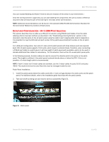
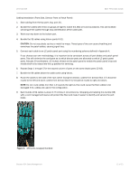
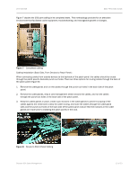
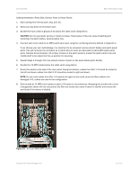
DATA CENTER BEST PRACTICES GUIDE Figure 7 depicts the 256 port cabling in its completed state. This methodology provides for an attractive environment that facilitates cooler equipment, troubleshooting, and manageable growth or changes. Figure 7. Completed cabling Cabling Installation (Back Side, From Devices to Patch Panel): When connecting cables from outside devices to the backside of the patch panel, the cables should be routed through the patch panel's backside punch-out holes. There are three options for routing cables through the back of the patch panel (Figure 8): 1. Remove the cable glands and run the cables through the punch-out holes in the back side of the patch panel. 2. Remove the cable glands, wrap a cord management sleeve around the cables, and run the cables through the punch-out holes in the back side of the patch panel. 3. Keep the cables glands in place, create (cut) incisions in the cable glands to prevent scraping of the cables against the metal and to allow for cable routing, and route the cables through the cable gland slots and the punch-out holes in the back side of the patch panel. Ensure that the incisions in the cable glands are made prior to installing the patch panels in the rack. Figure 8. Device to Patch Panel Cabling Brocade DCX Cable Management 13 of 23
-
 1
1 -
2
-
3
-
4
-
5
-
6
-
7
-
 8
8 -
 9
9 -
 10
10 -
 11
11 -
 12
12 -
 13
13 -
 14
14 -
 15
15 -
 16
16 -
 17
17 -
 18
18 -
19
-
20
-
21
-
22
-
23
 |
 |
