HP 2000sa HP Carrier-Grade Enclosure Installation Instructions (589728-002, Ju - Page 2
Power specifications, Replacing the power-and-cooling module, Preventing electrostatic discharge
 |
View all HP 2000sa manuals
Add to My Manuals
Save this manual to your list of manuals |
Page 2 highlights
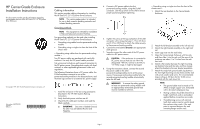
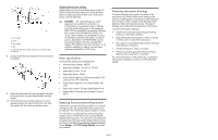
1. Lock washer 2. Screw 3. Flat washer 4. Bolt 5. Ground cable lug. Position between ear and rail (cable not shown). 8. Loosely attach the rear brackets to the rear bracket assemblies. 9. Attach the loose end of the ground cable to the front rack ground rail using the provided bolt and lock washer. 10. Verify that the Carrier-Grade Enclosure is evenly spaced between the right and left rack rails, and then tighten the front and rear bracket screws. Gigabit Ethernet port cabling Gigabit Ethernet Ports (intra-building ports) of the HP Carrier-Grade Enclosure require the use of shielded Ethernet cables grounded at both ends. Furthermore, please note the following: CAUTION: The intra-building ports of the equipment are suitable for connection to intra-building or unexposed wiring or cabling only. The intra-building ports of the equipment MUST NOT be metallically connected to interfaces that connect to the Outside Plant (OSP) or its wiring. These interfaces are designed for use as intra-building interfaces only (Type 2 or Type 4 ports as described in GR-1089-CORE, Issue 4) and require isolation from the exposed OSP cabling. The addition of primary protectors is not sufficient protection in order to connect these interfaces metallically to OSP wiring. Power specifications Environmental specifications (operational): • Nominal Input Voltage: -48VDC • Rated Input Voltage: -40 VDC to -75 VDC • Rated Input Current: 10.4A • Rated Input Power: 500W • Power load (single line, both lines powered): 220 watts per line, 441 watts total • Power load (single line, one line powered): 432 watts • Peak inrush current: 30 amps (specification limit) • Battery Return Terminals are Isolated DC Returns (DC-I) Replacing the power-and-cooling module In the event a power-and-cooling module or its internal cooling fan fails, the power-and-cooling module must be replaced. This should take approximately 5 minutes. For instructions on replacing the power-and-cooling module, see the HP DC Power and Cooling Module Replacement Instructions. This document is provided with the replacement DC power-and-cooling module and can also be found at http://www.hp.com/support/manuals. Under Storage, click Disk Storage Systems, and select your product. Preventing electrostatic discharge To prevent damaging the system, be aware of the precautions you need to follow when setting up the system or handling parts. A discharge of static electricity from a finger or other conductor may damage system boards or other static-sensitive devices. This type of damage may reduce the life expectancy of the device. To prevent electrostatic damage: • Avoid hand contact by transporting and storing products in static-safe containers. • Keep electrostatic-sensitive parts in their containers until they arrive at static-free workstations. • Place parts on a grounded surface before removing them from their containers. • Avoid touching pins, leads, or circuitry. • Always be properly grounded when touching a static-sensitive component or assembly. For more information on static electricity, or assistance with product installation, contact your HP authorized reseller. Page 2
-
 1
1 -
 2
2
 |
 |
