HP 245 HP 450 Notebook PC and HP 455 Notebook PC Maintenance and Service Guide - Page 95
Top cover see, Speakers see
 |
View all HP 245 manuals
Add to My Manuals
Save this manual to your list of manuals |
Page 95 highlights
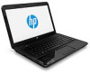
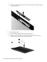
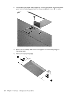
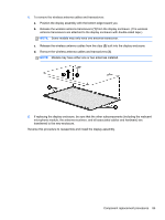
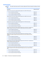
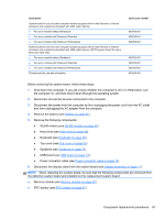
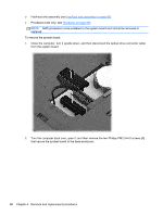
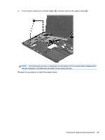
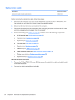
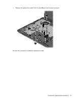
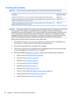
Description System board for use only with computer models equipped with an Intel Pentium or Celeron processor and a graphics subsystem with UMA video memory ● For use in models without Windows 8 ● For use in models with Windows 8 Standard ● For use in models with Windows 8 Professional System board for use only with computer models equipped with an Intel Pentium or Celeron processor and a graphics subsystem with UMA video memory (RCTO system board for use in Brazil and India only) ● For use in models without Windows 8 ● For use in models with Windows 8 Standard ● For use in models with Windows 8 Professional Thermal pad (for use with all models) Spare part number 685768-001 685768-501 685768-601 685783-001 685783-501 685783-601 651046-001 Before removing the system board, follow these steps: 1. Shut down the computer. If you are unsure whether the computer is off or in Hibernation, turn the computer on, and then shut it down through the operating system. 2. Disconnect all external devices connected to the computer. 3. Disconnect the power from the computer by first unplugging the power cord from the AC outlet and then unplugging the AC adapter from the computer. 4. Remove the battery (see Battery on page 41). 5. Remove the following components: ● WLAN module (see WLAN module on page 49) ● Hard drive (see Hard drive on page 54) ● Keyboard (see Keyboard on page 60) ● Top cover (see Top cover on page 63) ● Speakers (see Speakers on page 71) ● USB board (see USB board on page 73) ● Power connector cable (see Power connector cable on page 75) 6. Disconnect the display cable from the system board (see Display assembly on page 77). NOTE: When replacing the system board, be sure that the following components are removed from the defective system board and installed on the replacement system board: ● Memory module (see Memory module on page 52) ● RTC battery (see RTC battery on page 57) Component replacement procedures 87
-
 1
1 -
2
-
3
-
4
-
5
-
6
-
7
-
8
-
9
-
10
-
11
-
12
-
13
-
14
-
15
-
16
-
17
-
18
-
19
-
20
-
21
-
22
-
23
-
24
-
25
-
26
-
27
-
28
-
29
-
30
-
31
-
32
-
33
-
34
-
35
-
36
-
37
-
38
-
39
-
40
-
41
-
42
-
43
-
44
-
45
-
46
-
47
-
48
-
49
-
50
-
51
-
52
-
53
-
54
-
55
-
56
-
57
-
58
-
59
-
60
-
61
-
62
-
63
-
64
-
65
-
66
-
67
-
68
-
69
-
70
-
71
-
72
-
73
-
74
-
75
-
76
-
77
-
78
-
79
-
80
-
81
-
82
-
83
-
84
-
85
-
86
-
87
-
88
-
89
-
 90
90 -
 91
91 -
 92
92 -
 93
93 -
 94
94 -
 95
95 -
 96
96 -
 97
97 -
 98
98 -
 99
99 -
 100
100 -
101
-
102
-
103
-
104
-
105
-
106
-
107
-
108
-
109
-
110
-
111
-
112
-
113
-
114
-
115
-
116
-
117
-
118
-
119
-
120
-
121
-
122
-
123
-
124
-
125
-
126
-
127
-
128
-
129
-
130
-
131
-
132
-
133
-
134
-
135
-
136
-
137
-
138
-
139
-
140
-
141
-
142
 |
 |