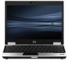
HP 2530p HP EliteBook 2530p Notebook PC - Maintenance and Service Guide
HP 2530p - EliteBook - Core 2 Duo 2.13 GHz Manual
 |
UPC - 884962204115
View all HP 2530p manuals
Add to My Manuals
Save this manual to your list of manuals |
HP 2530p manual content summary:
- HP 2530p | HP EliteBook 2530p Notebook PC - Maintenance and Service Guide - Page 1
HP EliteBook 2530p Notebook PC Maintenance and Service Guide - HP 2530p | HP EliteBook 2530p Notebook PC - Maintenance and Service Guide - Page 2
Microsystems, Inc. Microsoft, Windows, Windows XP, and Windows Vista are U.S. registered trademarks of Microsoft Corporation. SD Logo is a trademark of its proprietor. The information contained herein is subject to change without notice. The only warranties for HP products and services are set forth - HP 2530p | HP EliteBook 2530p Notebook PC - Maintenance and Service Guide - Page 3
or clothing, to block airflow. Also, do not allow the AC adapter to contact the skin or a soft surface, such as pillows or rugs or clothing, during operation. The computer and the AC adapter comply with the user-accessible surface temperature limits defined by the International Standard for Safety - HP 2530p | HP EliteBook 2530p Notebook PC - Maintenance and Service Guide - Page 4
iv Safety warning notice - HP 2530p | HP EliteBook 2530p Notebook PC - Maintenance and Service Guide - Page 5
identification Top components ...5 Pointing devices ...5 Lights ...6 Buttons, switches, and fingerprint reader 8 Keys ...10 Display ...11 Front components ...12 Rear components ...13 Right-side components ...14 Left-side components ...15 Bottom components ...17 Wireless antennae (select models only - HP 2530p | HP EliteBook 2530p Notebook PC - Maintenance and Service Guide - Page 6
41 Unknown user password 42 Component replacement procedures 43 Service tag ...44 Computer feet ...45 Battery ...46 SIM ...47 Bluetooth module ...48 Expansion memory module 50 WLAN module ...52 Primary hard drive ...55 WWAN module ...58 Optical drive ...60 Switch cover and keyboard 62 LED - HP 2530p | HP EliteBook 2530p Notebook PC - Maintenance and Service Guide - Page 7
WXGA display specifications 104 Hard drive specifications ...105 DVD-ROM Drive specifications ...106 DVD±RW and CD-RW SuperMulti Double-Layer Combo Drive specifications 107 System DMA specifications ...108 System interrupt specifications ...109 System I/O address specifications 110 System memory - HP 2530p | HP EliteBook 2530p Notebook PC - Maintenance and Service Guide - Page 8
10 Power cord set requirements Requirements for all countries and regions 144 Requirements for specific countries and regions 145 11 Recycling Battery ...146 Display ...147 Index ...152 viii - HP 2530p | HP EliteBook 2530p Notebook PC - Maintenance and Service Guide - Page 9
description Category Product Name Processors Chipset Graphics Panels Memory Description HP EliteBook 2530p Notebook PC Intel® LV Core™2 Duo, soldered uFBGA ● SL9600 2.13-GHz, 1066MHZ front side bus (FSB) with 6-MB cache ● SL9400 1.86-GHz, 1066MHz FSB with 6-MB cache ● SL9300 1.6-GHz, 1066MHz - HP 2530p | HP EliteBook 2530p Notebook PC - Maintenance and Service Guide - Page 10
-rpm ● 120-GB, 5400-rpm Fixed (removal of 1 screw required) NOTE: This option is not available with a secondary hard drive installed as primary storage. Customer-accessible Serial ATA (SATA) 9.5-mm tray load Supports the following drive options: ● DVD-ROM Drive ● DVD±RW and CD-RW SuperMulti Double - HP 2530p | HP EliteBook 2530p Notebook PC - Maintenance and Service Guide - Page 11
ports on models without an optical drive installed) VGA (Dsub 15-pin) supporting 1600 × 1200 external resolution at 75-GHz (hot plug/unplug with auto-detect) 3-pin AC power via the HP Smart AC Adapter HP 2400/2500 Series Docking Station Full-size 4.5-mm×19.05-mm keyboard with embedded numeric keypad - HP 2530p | HP EliteBook 2530p Notebook PC - Maintenance and Service Guide - Page 12
(32-bit) Vista Business (32-bit) Vista Ultimate (32-bit) FreeDOS End-user replaceable parts: AC adapter and power cord Battery (system) SIM Bluetooth module Memory module WLAN module WWAN module Optical drive RTC battery Switch cover Keyboard Primary hard drive Primary hard drive (solid-state) NOTE - HP 2530p | HP EliteBook 2530p Notebook PC - Maintenance and Service Guide - Page 13
on an external mouse. Scrolls up or down. (8) Right TouchPad button* Functions like the right button on an external mouse. *This table describes factory settings. To view or change pointing device preferences: ● For Windows Vista, select Start > Control Panel > Hardware and Sound > Mouse. ● For - HP 2530p | HP EliteBook 2530p Notebook PC - Maintenance and Service Guide - Page 14
the Sleep state (Windows Vista) or Standby (Windows XP). ● Off: The computer is off or in Hibernation. ● Blue: An integrated wireless device, such as a wireless local area network (WLAN) device, the HP Mobile Broadband Module, and/or a Bluetooth device, is on. ● Amber: All wireless devices are off - HP 2530p | HP EliteBook 2530p Notebook PC - Maintenance and Service Guide - Page 15
stays off until the battery reaches a low battery level. ● Blinking turquoise: The hard drive or optical drive is being accessed. ● Amber: HP 3D DriveGuard has temporarily parked the internal hard drive. *The 2 power lights display the same information. The light on the power button is visible only - HP 2530p | HP EliteBook 2530p Notebook PC - Maintenance and Service Guide - Page 16
> System and Maintenance > Power Options. ● For Windows XP, select Start > Control Panel > Performance and Maintenance > Power Options. Launches Info Center, which enables you to open various software solutions. Turns off the display if the display is closed while the power is on. Turns the wireless - HP 2530p | HP EliteBook 2530p Notebook PC - Maintenance and Service Guide - Page 17
can also press and hold the minus (-) sign to decrease volume, or press and hold the plus (+) sign to increase volume. Allows a fingerprint logon to Windows, instead of a password logon. Top components 9 - HP 2530p | HP EliteBook 2530p Notebook PC - Maintenance and Service Guide - Page 18
esc key (2) fn key (3) Windows logo key (4) Windows applications key (5) Embedded numeric keypad keys (6) Function keys Description Displays system information when pressed in combination with the fn key. Executes frequently used system functions when pressed in combination with a function key or - HP 2530p | HP EliteBook 2530p Notebook PC - Maintenance and Service Guide - Page 19
Ambient light sensor (2) Webcam light (select models only) (3) Webcam (select models only) (4) Keyboard light (5) Keyboard light button (6) Internal microphone Description Automatically adjusts the display brightness based on the lighting conditions in your environment. On: The integrated camera is - HP 2530p | HP EliteBook 2530p Notebook PC - Maintenance and Service Guide - Page 20
(2) Power light (3) Battery light (4) Drive light (5) Business card slot (6) Display release button Description ● Blue: An integrated wireless device, such as a wireless local area network (WLAN) device, the HP Mobile Broadband Module, and/or a Bluetooth device, is on. ● Amber: All wireless devices - HP 2530p | HP EliteBook 2530p Notebook PC - Maintenance and Service Guide - Page 21
Rear components Component (1) RJ-45 (network) jack (2) Security cable slot Description Connects a network cable. Attaches an optional security cable to the computer. NOTE: The security cable is designed to act as a deterrent, but it may not prevent the computer from being mishandled or stolen. - HP 2530p | HP EliteBook 2530p Notebook PC - Maintenance and Service Guide - Page 22
optional ExpressCards. Supports the Secure Digital (SD) Memory Card and MultiMediaCard (MMC) optional digital card formats. Connects an optional IEEE 1394 or 1394a device, such as a camcorder. Produces sound when connected to optional powered stereo speakers, headphones, ear buds, a headset, or - HP 2530p | HP EliteBook 2530p Notebook PC - Maintenance and Service Guide - Page 23
for the internal fan to cycle on and off during routine operation. Component (1) Power connector (2) RJ-11 (modem) jack (3) Powered USB port Description Connects an AC adapter. Connects a modem cable. Provides power to an external device if used with a powered USB cable. Left-side components 15 - HP 2530p | HP EliteBook 2530p Notebook PC - Maintenance and Service Guide - Page 24
(4) Vent (5) Optical drive Enables airflow to cool internal components. NOTE: The computer fan starts up automatically to cool internal components and prevent overheating. It is normal for the - HP 2530p | HP EliteBook 2530p Notebook PC - Maintenance and Service Guide - Page 25
module compartment (5) Vents (5) (6) Hard drive bay (7) Bluetooth compartment Description Release the battery from the battery bay. Holds the battery. Contains a wireless subscriber identity module (SIM). The SIM slot is located inside the battery bay. Contains an HP Mobile Broadband Module (select - HP 2530p | HP EliteBook 2530p Notebook PC - Maintenance and Service Guide - Page 26
by the governmental agency that regulates wireless devices in your country or region. If you replace the module and then receive a warning message, remove the module to restore computer functionality, and then contact technical support through Help and Support. 18 Chapter 2 External component - HP 2530p | HP EliteBook 2530p Notebook PC - Maintenance and Service Guide - Page 27
wireless signals to communicate with wireless local area networks (WLAN). (2) WWAN antennae (2)* Send and receive wireless signals to communicate with wireless areas immediately around the antennae free from obstructions. To see wireless regulatory notices, refer to the section of the Regulatory, - HP 2530p | HP EliteBook 2530p Notebook PC - Maintenance and Service Guide - Page 28
provides information that may be needed when troubleshooting system problems. The service tag provides the following information: (1) Product service technician to determine what components and parts are needed. (4) Model description: This is the number used to locate documents, drivers, and support - HP 2530p | HP EliteBook 2530p Notebook PC - Maintenance and Service Guide - Page 29
Serial number location 21 - HP 2530p | HP EliteBook 2530p Notebook PC - Maintenance and Service Guide - Page 30
Computer major components Item (1) Description Spare part number 12.1-inch, WXGA AntiGlare display assembly (See Display components on page 27 for display assembly component spare part number information.) With webcam 492576-001 Without webcam 492575-001 22 Chapter 3 Illustrated parts - HP 2530p | HP EliteBook 2530p Notebook PC - Maintenance and Service Guide - Page 31
4a) (4b) Description Switch cover (includes display lid switch board and cable) Keyboard with pointing stick (includes keyboard cable and pointing stick for more Plastics Kit spare part information): ExpressCard slot insert Bluetooth module compartment cover Spare part number 492556-001 506677-201 - HP 2530p | HP EliteBook 2530p Notebook PC - Maintenance and Service Guide - Page 32
Spare part number Broadband wireless module compartment cover Memory module compartment cover Hard drive bay cover NOTE: The 4.57-cm (1.80-inch) primary hard drive must be installed in the hard drive bay. Installation of this drive in the optical drive bay is not supported. LED board (includes - HP 2530p | HP EliteBook 2530p Notebook PC - Maintenance and Service Guide - Page 33
Ukraine, the United Arab Emirates, the United Kingdom, Uruguay, Uzbekistan, Vanuatu, Venezuela, Vietnam, Yemen, Zaire, Zambia, and Zimbabwe ● Broadcom 4322AGN WiFi Adapter for use in the United States and Canada 487330-001 ● Intel WiFi Link 5100ABGN with Active Management Technology (AMT) for use - HP 2530p | HP EliteBook 2530p Notebook PC - Maintenance and Service Guide - Page 34
Module 483377-002 Battery 9-cell, 83.0-WH Li-ion 492550-001 6-cell, 55.0-WH Li-ion 492549-001 3-cell, 31.0-WH Li-ion 492548-001 Bluetooth module 483113-001 Memory module (PC2-6400, 800-MHz, DDR2) 4-GB 492572-001 2-GB 492571-001 1-GB 492570-001 Primary hard drive (includes bezel and - HP 2530p | HP EliteBook 2530p Notebook PC - Maintenance and Service Guide - Page 35
panel cable For use with models that include a webcam For use with models that do not include a webcam Microphone Display enclosure (includes HP logo, wireless antenna transceivers, and cables) Spare part number 492576-001 492575-001 495022-001 495019-001 497013-001 481098-001 495023-001 495021-001 - HP 2530p | HP EliteBook 2530p Notebook PC - Maintenance and Service Guide - Page 36
Item Description With webcam Without webcam Spare part number 496490-001 495020-001 28 Chapter 3 Illustrated parts catalog - HP 2530p | HP EliteBook 2530p Notebook PC - Maintenance and Service Guide - Page 37
inch) primary hard drive must be installed in the hard drive bay. Installation of this drive in the optical drive bay is not supported. 160-GB, 5400-rpm hard drive 503732-001 120-GB, 5400-rpm hard drive 492560-001 80-GB, 5400-rpm hard drive 492565-001 80-GB, solid-state hard drive 492566-001 - HP 2530p | HP EliteBook 2530p Notebook PC - Maintenance and Service Guide - Page 38
Item Description Spare part number Secondary hard drive system connector board (required for installation of secondary hard 495028-001 drive) (3) Optical drive DVD-ROM Drive 492558-001 DVD±RW and CD-RW SuperMulti Double-Layer Combo Drive 492559-001 30 Chapter 3 Illustrated parts catalog - HP 2530p | HP EliteBook 2530p Notebook PC - Maintenance and Service Guide - Page 39
Kit: 492577-001 (1) ExpressCard slot insert (2) Bluetooth module compartment cover (includes one captive screw, secured by a C-clip) (3) Broadband wireless module compartment cover (includes one captive screw, secured by a C-clip) (4) Hard drive bay cover (includes 2 captive screws, secured by - HP 2530p | HP EliteBook 2530p Notebook PC - Maintenance and Service Guide - Page 40
Miscellaneous parts Description 65-W Smart AC Adapter Cable Kit, includes Bluetooth, LED, and modem cables Optical drive bay insert assembly, includes additional USB port Power cord Rubber Kit (includes all rubber/mylar computer components) Screw Kit Smart card reader Spare part number 463958-001 - HP 2530p | HP EliteBook 2530p Notebook PC - Maintenance and Service Guide - Page 41
Zealand 65-W Smart AC Adapter Intel WiFi Link battery Display Hinge Kit (includes left and right hinges and brackets) Speaker Intel WiFi Link 5100ABG (802.11a/b/g WLAN module) for use in the United States and Canada Bluetooth module HP un2400 Mobile Broadband Module Broadcom 4322AGN WiFi Adapter - HP 2530p | HP EliteBook 2530p Notebook PC - Maintenance and Service Guide - Page 42
, Vietnam, Yemen, Zaire, Zambia, and Zimbabwe Power cord Base enclosure (includes display latch switch, battery release latch, and rubber feet) 3-cell, 31.0-Wh Li-ion battery 6-cell, 55.0-Wh Li-ion battery 9-cell, 83.0-Wh Li-ion battery System board with LV SL9300 processor (includes processor - HP 2530p | HP EliteBook 2530p Notebook PC - Maintenance and Service Guide - Page 43
with webcam (includes HP logo, wireless antenna transceivers and cables) Display bezel adhesive Optical drive bay insert assembly, includes additional USB port LED board (includes cable and Mylar cover) 160-GB, 5400-rpm, 4.57-cm (1.80-inch ) primary hard drive Keyboard with pointing stick for - HP 2530p | HP EliteBook 2530p Notebook PC - Maintenance and Service Guide - Page 44
thermal material cleaning kit) 250-GB, 5400-rpm, 6.35-cm (2.50-inch) secondary hard drive 320-GB, 7200-rpm, 6.35-cm (2.50-inch) secondary hard drive 160-GB, 5400-rpm, 6.35-cm (2.50-inch) secondary hard drive Top cover (includes TouchPad board and cable, TouchPad button board and cable, and TouchPad - HP 2530p | HP EliteBook 2530p Notebook PC - Maintenance and Service Guide - Page 45
to complete the removal and replacement procedures: ● Flat-bladed screwdriver ● Magnetic screwdriver ● Phillips P0 and P1 screwdrivers ● Torx T8 screwdriver Service considerations The pressure only at the points designated in the maintenance instructions. Preliminary replacement requirements 37 - HP 2530p | HP EliteBook 2530p Notebook PC - Maintenance and Service Guide - Page 46
Cables and connectors CAUTION: When servicing the computer, be sure that cables are placed in Avoid dropping drives from any height onto any surface. After removing an internal hard drive, an optical drive, or a diskette drive, place it in a static-proof bag. Avoid exposing an internal hard drive to - HP 2530p | HP EliteBook 2530p Notebook PC - Maintenance and Service Guide - Page 47
protection, but in many cases, ESD contains enough power to alter device parameters or melt silicon junctions. A discharge of device may function normally for a while, then degrade in the internal layers, reducing its life expectancy. CAUTION: To prevent damage to the computer when you are removing - HP 2530p | HP EliteBook 2530p Notebook PC - Maintenance and Service Guide - Page 48
work surface and use properly grounded tools and equipment. ● Use conductive field service tools, such as cutters, screwdrivers, and vacuums. ● When fixtures must pins, leads, or circuitry. ● Turn off power and input signals before inserting or removing connectors or test equipment. 40 Chapter - HP 2530p | HP EliteBook 2530p Notebook PC - Maintenance and Service Guide - Page 49
wrist strap connected to a grounded system. Wrist straps are flexible straps with a minimum of one megohm ±10% resistance in the ground cords. To provide proper ground, wear a cords of one megohm resistance ● Static-dissipative tables or floor mats with hard ties to the ground ● Field service - HP 2530p | HP EliteBook 2530p Notebook PC - Maintenance and Service Guide - Page 50
the operating system. 2. Disconnect all external devices connected to the computer. 3. Disconnect the power from the computer by first unplugging the power cord from the AC outlet and then unplugging the AC adapter from the computer. 4. Remove the battery (see Battery on page 46). 5. Remove the real - HP 2530p | HP EliteBook 2530p Notebook PC - Maintenance and Service Guide - Page 51
procedures This chapter provides removal and replacement procedures. There are as many as 60 screws, in 9 different sizes, that must be removed, replaced, or loosened when servicing the computer. Make special note of each screw size and location during removal and replacement. Component replacement - HP 2530p | HP EliteBook 2530p Notebook PC - Maintenance and Service Guide - Page 52
, provides information that may be needed when troubleshooting system problems. The service tag provides the following information: (1) Product drivers, and support for the computer. (5) Warranty period: This number describes the duration of the warranty period for the computer. 44 Chapter 4 Removal - HP 2530p | HP EliteBook 2530p Notebook PC - Maintenance and Service Guide - Page 53
Computer feet The computer feet are adhesive-backed rubber pads. The feet are included in the Rubber Kit, spare part number 492578-001. There are 4 rubber feet that attach to the base enclosure in the locations illustrated below. Component replacement procedures 45 - HP 2530p | HP EliteBook 2530p Notebook PC - Maintenance and Service Guide - Page 54
it down through the operating system. 2. Disconnect all external devices connected to the computer. 3. Disconnect the power from the computer by first unplugging the power cord from the AC outlet and then unplugging the AC adapter from the computer. Remove the battery: 1. Turn the computer upside - HP 2530p | HP EliteBook 2530p Notebook PC - Maintenance and Service Guide - Page 55
the operating system. 2. Disconnect all external devices connected to the computer. 3. Disconnect the power from the computer by first unplugging the power cord from the AC outlet and then unplugging the AC adapter from the computer. 4. Remove the battery (see Battery on page 46). Remove the SIM - HP 2530p | HP EliteBook 2530p Notebook PC - Maintenance and Service Guide - Page 56
operating system. 2. Disconnect all external devices connected to the computer. 3. Disconnect the power from the computer by first unplugging the power cord from the AC outlet and then unplugging the AC adapter from the computer. 4. Remove the battery (see Battery on page 46). Remove the Bluetooth - HP 2530p | HP EliteBook 2530p Notebook PC - Maintenance and Service Guide - Page 57
5. Remove the Bluetooth module (3). Reverse the above procedure to install the Bluetooth module. Component replacement procedures 49 - HP 2530p | HP EliteBook 2530p Notebook PC - Maintenance and Service Guide - Page 58
the operating system. 2. Disconnect all external devices connected to the computer. 3. Disconnect the power from the computer by first unplugging the power cord from the AC outlet and then unplugging the AC adapter from the computer. 4. Remove the battery (see Battery on page 46). Remove the memory - HP 2530p | HP EliteBook 2530p Notebook PC - Maintenance and Service Guide - Page 59
4. Remove the memory module (2) by pulling the module away from the slot at an angle. NOTE: The memory module is designed with a notch (3) to prevent incorrect insertion into the memory module slot. Reverse this procedure to install the memory module. Component replacement procedures 51 - HP 2530p | HP EliteBook 2530p Notebook PC - Maintenance and Service Guide - Page 60
, Uzbekistan, Vanuatu, Venezuela, Vietnam, Yemen, Zaire, Zambia, and Zimbabwe ● Broadcom 4322AGN WiFi Adapter (802.11a/b/g/n WLAN module): For use in the United States 487330-001 and Canada ● Intel For use in the United States and Canada 506680-001 52 Chapter 4 Removal and replacement procedures - HP 2530p | HP EliteBook 2530p Notebook PC - Maintenance and Service Guide - Page 61
the operating system. 2. Disconnect all external devices connected to the computer. 3. Disconnect the power from the computer by first unplugging the power cord from the AC outlet and then unplugging the AC adapter from the computer. 4. Remove the battery (see Battery on page 46). Remove the WLAN - HP 2530p | HP EliteBook 2530p Notebook PC - Maintenance and Service Guide - Page 62
WLAN antenna cable is connected to the WLAN module "Main" terminal. The white WLAN antenna cable is connected to the WLAN module "Aux" terminal. 4. Remove the two Phillips PM2.0×4.0 screws (2) that secure the WLAN module to the computer. (The edge of the module opposite the slot rises away from the - HP 2530p | HP EliteBook 2530p Notebook PC - Maintenance and Service Guide - Page 63
system. 2. Disconnect all external devices connected to the computer. 3. Disconnect the power from the computer by first unplugging the power cord from the AC outlet and then unplugging the AC adapter from the computer. 4. Remove the battery (see Battery on page 46). Remove the primary hard drive - HP 2530p | HP EliteBook 2530p Notebook PC - Maintenance and Service Guide - Page 64
4. Loosen the 2 Phillips 2.0×6.0 captive screws (1) that secure the hard drive bracket, and remove the hard drive bracket (2). 5. Remove the Phillips screw that secures the connector board to the base enclosure(3). 6. Tilt the primary hard drive up toward you (1) to disengage it from the compartment - HP 2530p | HP EliteBook 2530p Notebook PC - Maintenance and Service Guide - Page 65
edges of the protective rubber gasket out and away from the hard drive (1), and remove the gasket (2). 10. If it is necessary to replace the primary hard drive connector board, release the ZIF connectors (1) to which the primary hard drive connector board cable is attached, and disconnect the cable - HP 2530p | HP EliteBook 2530p Notebook PC - Maintenance and Service Guide - Page 66
the operating system. 2. Disconnect all external devices connected to the computer. 3. Disconnect the power from the computer by first unplugging the power cord from the AC outlet and then unplugging the AC adapter from the computer. 4. Remove the battery (see Battery on page 46). Remove the WWAN - HP 2530p | HP EliteBook 2530p Notebook PC - Maintenance and Service Guide - Page 67
two Phillips PM2.0×4.0 screws that secure the module to the computer (2). 6. Remove the WWAN module (3) by pulling the module away from the slot at an angle. NOTE: WWAN modules are designed with a notch (4) to prevent incorrect insertion. - HP 2530p | HP EliteBook 2530p Notebook PC - Maintenance and Service Guide - Page 68
the operating system. 2. Disconnect all external devices connected to the computer. 3. Disconnect the power from the computer by first unplugging the power cord from the AC outlet and then unplugging the AC adapter from the computer. 4. Remove the battery (see Battery on page 46). 5. Remove the - HP 2530p | HP EliteBook 2530p Notebook PC - Maintenance and Service Guide - Page 69
7. Remove the optical drive bracket (2). Reverse this procedure to reassemble and install an optical drive. Component replacement procedures 61 - HP 2530p | HP EliteBook 2530p Notebook PC - Maintenance and Service Guide - Page 70
Thailand ● For use in Turkey ● For use in the United Kingdom ● For use in the United States Before removing the switch cover and keyboard, follow these steps: 62 Chapter 4 Removal and replacement procedures Spare part number 492556-001 506677-201 506677-221 506677-081 506677-021 506677-B71 506677 - HP 2530p | HP EliteBook 2530p Notebook PC - Maintenance and Service Guide - Page 71
the operating system. 2. Disconnect all external devices connected to the computer. 3. Disconnect the power from the computer by first unplugging the power cord from the AC outlet and then unplugging the AC adapter from the computer. 4. Remove the battery (see Battery on page 46). 5. Remove the WWAN - HP 2530p | HP EliteBook 2530p Notebook PC - Maintenance and Service Guide - Page 72
connector (3) to which the pointing stick cable is attached, and disconnect the pointing stick cable (4) from the system board. 10. Remove the keyboard. 11. Disconnect the LED board cable (1) and the power button board cable (2) from the system board. 64 Chapter 4 Removal and replacement procedures - HP 2530p | HP EliteBook 2530p Notebook PC - Maintenance and Service Guide - Page 73
12. Remove the switch cover. Reverse this procedure to install the switch cover and keyboard. Component replacement procedures 65 - HP 2530p | HP EliteBook 2530p Notebook PC - Maintenance and Service Guide - Page 74
external devices connected to the computer. 3. Disconnect the power from the computer by first unplugging the power cord from the AC outlet and then unplugging the AC adapter from the computer. 4. Remove the battery (see Battery on page 46). 5. Remove the following components: a. Primary hard drive - HP 2530p | HP EliteBook 2530p Notebook PC - Maintenance and Service Guide - Page 75
external devices connected to the computer. 3. Disconnect the power from the computer by first unplugging the power cord from the AC outlet and then unplugging the AC adapter from the computer. 4. Remove the battery (see Battery on page 46). 5. Release the switch cover and keyboard (see Switch cover - HP 2530p | HP EliteBook 2530p Notebook PC - Maintenance and Service Guide - Page 76
by first unplugging the power cord from the AC outlet and then unplugging the AC adapter from the computer. 4. Remove the battery. (See Battery on page 46) 5. Remove the switch cover and keyboard. (See Switch cover and keyboard on page 62) Remove the secondary hard drive: 1. Close the display, and - HP 2530p | HP EliteBook 2530p Notebook PC - Maintenance and Service Guide - Page 77
2. Remove the 5 Mylar screw covers (1), the 4 Phillips screws (2), and the 2 Phillips PM2.0×6.0 screws (3) that secure the secondary hard drive cradle assembly to the computer. 3. Turn the computer right-side up, and open the display as far as possible. 4. Disconnect the secondary hard drive cradle - HP 2530p | HP EliteBook 2530p Notebook PC - Maintenance and Service Guide - Page 78
the secondary hard drive cradle assembly (3) from the optical drive bay. 7. Remove the four Phillips PM3.0×4.0 secondary hard drive screws that secure the secondary hard drive to the cradle assembly. 8. Tilt the hard drive up and away from the connector board (1), and disconnect the hard drive from - HP 2530p | HP EliteBook 2530p Notebook PC - Maintenance and Service Guide - Page 79
the two Phillips screws that secure the connector board to the cradle assembly (1). 11. Remove the secondary hard drive connector board (2). 12. If it is necessary to replace the secondary hard drive system connector board, remove the two Phillips screws that secure the connector board to the cradle - HP 2530p | HP EliteBook 2530p Notebook PC - Maintenance and Service Guide - Page 80
14. Remove the secondary hard drive system connector board (4). Reverse the above procedure to reassemble and install the secondary hard drive. 72 Chapter 4 Removal and replacement procedures - HP 2530p | HP EliteBook 2530p Notebook PC - Maintenance and Service Guide - Page 81
external devices connected to the computer. 3. Disconnect the power from the computer by first unplugging the power cord from the AC outlet and then unplugging the AC adapter from the computer. 4. Remove the battery (see Battery on page 46). 5. Release the switch cover and keyboard (see Switch cover - HP 2530p | HP EliteBook 2530p Notebook PC - Maintenance and Service Guide - Page 82
system. 2. Disconnect all external devices connected to the computer. 3. Disconnect the power from the computer by first unplugging the power cord from the AC outlet and then unplugging the AC adapter from the computer. 4. Remove the battery (see Battery on page 46). 5. Remove the Bluetooth - HP 2530p | HP EliteBook 2530p Notebook PC - Maintenance and Service Guide - Page 83
3. Disconnect the wireless antenna cables from the WWAN module (3), and feed them down through the hole (4). 4. Turn the computer right side up, and open the display . 5. Thread the - HP 2530p | HP EliteBook 2530p Notebook PC - Maintenance and Service Guide - Page 84
9. Open the computer. CAUTION: The display assembly will be unsupported when the following screws are removed. To prevent damage to the display assembly, support it before removing the screws. 10. Remove the two Torx8 T8M2.5×6.0 screws (one at each hinge) (1) that secure the display assembly hinges - HP 2530p | HP EliteBook 2530p Notebook PC - Maintenance and Service Guide - Page 85
the top (3) of the display bezel until the bezel disengages from the display enclosure. 14. Remove the display bezel (4). NOTE: Remove excess adhesive from the bezel and display enclosure when you remove the bezel, and reapply adhesive before replacing the bezel. 15. If it is necessary to replace - HP 2530p | HP EliteBook 2530p Notebook PC - Maintenance and Service Guide - Page 86
two Phillips PM2.0×4.0 screws (1) that secure each display hinge to the display panel. 19. Remove the display hinges (2). 20. If it is necessary to replace the display panel cable, (1). 22. Disconnect the display panel cable (2) from the display panel. 78 Chapter 4 Removal and replacement procedures - HP 2530p | HP EliteBook 2530p Notebook PC - Maintenance and Service Guide - Page 87
23. Remove the display panel cable (3). 24. If it is necessary to replace the microphones (1), remove the microphones from the display enclosure (2). Reverse this procedure to reassemble and install the display assembly. Component replacement procedures 79 - HP 2530p | HP EliteBook 2530p Notebook PC - Maintenance and Service Guide - Page 88
external devices connected to the computer. 3. Disconnect the power from the computer by first unplugging the power cord from the AC outlet and then unplugging the AC adapter from the computer. 4. Remove the battery (see Battery on page 46). 5. Remove the following components: a. Primary hard drive - HP 2530p | HP EliteBook 2530p Notebook PC - Maintenance and Service Guide - Page 89
2. Remove the following screw covers and screws: (1) Four rubber screw covers. The rubber you. 4. Disconnect the TouchPad cable (1), and the fingerprint reader board cable (2) from the system board. 5. Remove the two Torx T8M2.5×6.0 screws (3) and the Phillips PM2.0×6.0 screw (4) that secure the top - HP 2530p | HP EliteBook 2530p Notebook PC - Maintenance and Service Guide - Page 90
(1) and swing it up and forward until it rests at an angle. 7. Lift the front edge of the top cover (2) until it disengages from the base enclosure. 8. Remove the top cover. Reverse this procedure to install the top cover. 82 Chapter 4 Removal and replacement procedures - HP 2530p | HP EliteBook 2530p Notebook PC - Maintenance and Service Guide - Page 91
external devices connected to the computer. 3. Disconnect the power from the computer by first unplugging the power cord from the AC outlet and then unplugging the AC adapter from the computer. 4. Remove the battery (see Battery on page 46). 5. Remove the following components: a. Primary hard drive - HP 2530p | HP EliteBook 2530p Notebook PC - Maintenance and Service Guide - Page 92
external devices connected to the computer. 3. Disconnect the power from the computer by first unplugging the power cord from the AC outlet and then unplugging the AC adapter from the computer. 4. Remove the battery (see Battery on page 46). 5. Remove the following components: a. Primary hard drive - HP 2530p | HP EliteBook 2530p Notebook PC - Maintenance and Service Guide - Page 93
RJ-11 jack and USB ports are clear of the openings in the base enclosure. 5. Use the optical drive connector (2) to lift the left side of the system board (3) until it rests at an angle. 6. Remove the system board (4) from the base enclosure by sliding it up and to the left. Reverse this procedure - HP 2530p | HP EliteBook 2530p Notebook PC - Maintenance and Service Guide - Page 94
external devices connected to the computer. 3. Disconnect the power from the computer by first unplugging the power cord from the AC outlet and then unplugging the AC adapter from the computer. 4. Remove the battery (see Battery on page 46). 5. Remove the following components: a. Primary hard drive - HP 2530p | HP EliteBook 2530p Notebook PC - Maintenance and Service Guide - Page 95
3. Turn the system board rightside up, with the rear toward you. 4. Remove the ExpressCard assembly. Reverse this procedure to install the ExpressCard assembly. Component replacement procedures 87 - HP 2530p | HP EliteBook 2530p Notebook PC - Maintenance and Service Guide - Page 96
external devices connected to the computer. 3. Disconnect the power from the computer by first unplugging the power cord from the AC outlet and then unplugging the AC adapter from the computer. 4. Remove the battery (see Battery on page 46). 5. Remove the following components: a. Primary hard drive - HP 2530p | HP EliteBook 2530p Notebook PC - Maintenance and Service Guide - Page 97
4. Remove the modem module . Reverse this procedure to install the modem module. Component replacement procedures 89 - HP 2530p | HP EliteBook 2530p Notebook PC - Maintenance and Service Guide - Page 98
external devices connected to the computer. 3. Disconnect the power from the computer by first unplugging the power cord from the AC outlet and then unplugging the AC adapter from the computer. 4. Remove the battery (see Battery on page 46). 5. Remove the following components: a. Primary hard drive - HP 2530p | HP EliteBook 2530p Notebook PC - Maintenance and Service Guide - Page 99
4. Lift the fan up (3) to remove. Reverse this procedure to install the fan. Component replacement procedures 91 - HP 2530p | HP EliteBook 2530p Notebook PC - Maintenance and Service Guide - Page 100
external devices connected to the computer. 3. Disconnect the power from the computer by first unplugging the power cord from the AC outlet and then unplugging the AC adapter from the computer. 4. Remove the battery (see Battery on page 46). 5. Remove the following components: a. Primary hard drive - HP 2530p | HP EliteBook 2530p Notebook PC - Maintenance and Service Guide - Page 101
NOTE: The thermal material must be thoroughly cleaned from the surfaces of the heat sink and system board each time the heat sink is removed. Thermal paste and pads are located on the heat sink (1) and on system board components (2). Replacement thermal material is included with all heat sink and - HP 2530p | HP EliteBook 2530p Notebook PC - Maintenance and Service Guide - Page 102
Computer Setup is a preinstalled, ROM-based utility that can be used even when the operating system is not working or will not load. NOTE: Some of the Computer Setup menu items listed in this guide may not be supported by your computer. NOTE: An external keyboard or mouse connected to a USB port - HP 2530p | HP EliteBook 2530p Notebook PC - Maintenance and Service Guide - Page 103
follow the on-screen instructions. NOTE: You can use either a pointing device (TouchPad, pointing stick, or USB mouse) or the keyboard to navigate and make selections in Computer Setup. 2. Press f10 to enter BIOS Setup. 3. Select the File, Security, Diagnostics, or System Configuration menu. To exit - HP 2530p | HP EliteBook 2530p Notebook PC - Maintenance and Service Guide - Page 104
for Startup Menu" message is displayed at the bottom of the screen. 2. Press f10 to enter BIOS Setup. 3. Use a pointing device or the arrow keys to select File > Restore defaults. 4. Follow the on-screen instructions. 5. To save your changes and exit, click the Save icon in the lower-left corner of - HP 2530p | HP EliteBook 2530p Notebook PC - Maintenance and Service Guide - Page 105
system. ● View specification information for the processor, cache and memory size, system ROM, video revision, and keyboard controller version. Set or change the date and time on the computer. Replace the configuration settings in Computer Setup with the original factory settings. (Hard drive mode - HP 2530p | HP EliteBook 2530p Notebook PC - Maintenance and Service Guide - Page 106
a BIOS administrator password. HP SpareKey Enrollment DriveLock Passwords Enroll or reset HP SpareKey, which is a set of security questions and answers used if you forget your password. ● Enable/disable DriveLock on any computer hard drive (enabled by default). ● Change a DriveLock user password - HP 2530p | HP EliteBook 2530p Notebook PC - Maintenance and Service Guide - Page 107
: ◦ Identification information for the computer and the batteries in the system. ◦ Specification information for the processor, cache and memory size, system ROM, video revision, and keyboard controller version. ● F2 Start-up Test-Verifies the system components needed for starting the computer. ● F3 - HP 2530p | HP EliteBook 2530p Notebook PC - Maintenance and Service Guide - Page 108
by default). When enabled, USB legacy support allows the following: ◦ Use of a USB keyboard in Computer Setup even when a Windows® operating system is not running. ◦ Startup from bootable USB devices, including a hard drive, diskette drive, or optical drive connected by a USB port to the computer - HP 2530p | HP EliteBook 2530p Notebook PC - Maintenance and Service Guide - Page 109
(UEFI) mode (disabled by default). ● Enable/disable the wireless button state (enabled by default). ● Enable/disable embedded WWAN device radio (select models only; enabled by default). ● Enable/disable embedded Bluetooth device radio (enabled by default). ● Enable/disable the Network Interface - HP 2530p | HP EliteBook 2530p Notebook PC - Maintenance and Service Guide - Page 110
disables MultiBay devices and ExpressCard devices on the advanced port replicator. ● Enable/disable the 1394 port. NOTE: All AMT options are disabled by default. ● Enable/disable Firmware Verbosity. ● Enable/disable AMT Setup Prompt (CTRL-P). ● Enable/disable USB Key Provisioning Support. ● Enable - HP 2530p | HP EliteBook 2530p Notebook PC - Maintenance and Service Guide - Page 111
, and WLAN module Equipped with DVD-ROM Drive, 3-cell battery, and WLAN module Equipped with 3-cell battery and WLAN module 1.64 kg 1.48 kg 1.29 kg 3.62 lbs 3.26 lbs 2.84 lbs Input power Operating voltage Operating current Temperature 18.5 V dc @ 3.50 A - 65 W 3.50 A Operating (reading to - HP 2530p | HP EliteBook 2530p Notebook PC - Maintenance and Service Guide - Page 112
12.1-inch, WXGA display specifications Dimensions Height Width Diagonal Number of colors Contrast ratio Brightness Pixel resolution Pitch Format Configuration Backlight Character display Total power consumption Viewing angle Metric U.S. 16.9 cm 26.2 cm 30.8 cm Up to 16.8 million 250:1 (typical) - HP 2530p | HP EliteBook 2530p Notebook PC - Maintenance and Service Guide - Page 113
NOTE: Certain restrictions and exclusions apply. Consult technical support for details. 3 ms 13 ms 24 ms 158,624,849 *1 GB = 1 billion bytes when referring to hard drive storage capacity. Accessible capacity is less. Actual drive specifications may differ slightly. Hard drive specifications 105 - HP 2530p | HP EliteBook 2530p Notebook PC - Maintenance and Service Guide - Page 114
DVD-ROM Drive specifications Applicable disc Access time Random Cache buffer Data transfer rate CD-R (24X) CD-RW (10X) CD-ROM (24X) DVD Transfer mode DVD-ROM (DVD-5, DVD (150 KB/s at 1X CD rate) 10,800 KB/sec (1,352 KB/s at 1X DVD rate) 16.6 MB/sec Multiword DMA mode 2 106 Chapter 6 Specifications - HP 2530p | HP EliteBook 2530p Notebook PC - Maintenance and Service Guide - Page 115
DVD±RW and CD-RW SuperMulti Double-Layer Combo Drive specifications Applicable disc Access time Random Cache buffer Data transfer rate 24X CD-ROM 8X DVD 24X CD-R 16X CD-RW 8X DVD+R 4X DVD+RW 8X DVD-R 4X DVD-RW 2.4X DVD+R(9) 5X DVD-RAM Transfer mode Read: Write: CD-DA, CD+(E)G, CD - HP 2530p | HP EliteBook 2530p Notebook PC - Maintenance and Service Guide - Page 116
System DMA specifications Hardware DMA System function DMA0 Not applicable DMA1* Not applicable DMA2* Not applicable DMA3 Not applicable DMA4 Direct memory access controller DMA5* Available for ExpressCard DMA6 Not assigned DMA7 - HP 2530p | HP EliteBook 2530p Notebook PC - Maintenance and Service Guide - Page 117
System interrupt specifications Hardware IRQ System function IRQ0 IRQ1 System timer Standard 101-/102-Key or Microsoft® Natural Keyboard IRQ2 IRQ3 IRQ4 IRQ5* IRQ6 IRQ7* IRQ8 Cascaded Intel 82801DB/DBM USB2 Enhanced Host Controller-24CD COM1 Conexant AC-Link Audio Intel 82801DB/DBM SMBus - HP 2530p | HP EliteBook 2530p Notebook PC - Maintenance and Service Guide - Page 118
Counter/timer registers Unused Keyboard controller Port B Unused Keyboard controller Unused NMI enable/RTC Unused DMA page registers Unused Port A Unused Interrupt controller no. 2 System Function (shipping configuration) Unused DMA controller no. 2 Unused Coprocessor busy clear/reset Unused Unused - HP 2530p | HP EliteBook 2530p Notebook PC - Maintenance and Service Guide - Page 119
function (shipping configuration) Entertainment audio Unused Unused Unused Unused Unused Unused Reserved serial port Unused Infrared port Unused Unused Secondary diskette drive controller Parallel port (LPT1/default) Unused FM synthesizer-OPL3 Unused VGA Reserved (parallel port/no EPP support) VGA - HP 2530p | HP EliteBook 2530p Notebook PC - Maintenance and Service Guide - Page 120
-00FFFFFF 04800000-07FFFFFF 04800000-07FFFFFF 08000000-080FFFFF 08200000-FFFEFFFF FFFF0000-FFFFFFFF System function Base memory Video memory Video BIOS Unused System BIOS Extended memory Super extended memory Unused Video memory (direct access) Unused System BIOS 112 Chapter 6 Specifications - HP 2530p | HP EliteBook 2530p Notebook PC - Maintenance and Service Guide - Page 121
7 Screw listing This section provides specification and reference information for the screws and screw locks used in the computer. All screws listed in this section are available in the Screw Kit, spare part number 492579-001. 113 - HP 2530p | HP EliteBook 2530p Notebook PC - Maintenance and Service Guide - Page 122
Phillips PM 2.0×4.0 screw Color Black Quantity 16 Length 4.0 mm Thread 2.0 mm Head diameter 4.5 mm Where used: 1 screw that secures the Bluetooth module to the Bluetooth module compartment cover Where used: 2 screws that secure the WLAN module to the base enclosure 114 Chapter 7 Screw listing - HP 2530p | HP EliteBook 2530p Notebook PC - Maintenance and Service Guide - Page 123
Where used: 2 screws that secure the WWAN board to the base enclosure Where used: 2 screws that secure the optical drive bracket to the optical drive Where used: 4 screws that secure the display hinges to the display panel Phillips PM 2.0×4.0 screw 115 - HP 2530p | HP EliteBook 2530p Notebook PC - Maintenance and Service Guide - Page 124
Where used: One screw that secures the top cover to the base enclosure Where used: One screw that secures the speaker to the base enclosure Where used: 2 screws that secure the modem module to the system board 116 Chapter 7 Screw listing - HP 2530p | HP EliteBook 2530p Notebook PC - Maintenance and Service Guide - Page 125
Where used: One screw that secures the fan to the system board Phillips PM 2.0×4.0 screw 117 - HP 2530p | HP EliteBook 2530p Notebook PC - Maintenance and Service Guide - Page 126
Torx T8M2.0×5.0 screw Color Black Quantity 13 Length 5.0 mm Thread 2.0 mm Head diameter 4.5 mm Where used: 2 screws that secure the optical drive to the computer Where used: 2 screws that secure the display assembly to the computer 118 Chapter 7 Screw listing - HP 2530p | HP EliteBook 2530p Notebook PC - Maintenance and Service Guide - Page 127
Where used: 4 screws that connect the bezel to the display assembly Where used: One screw that secures the top cover to the base enclosure Where used: One screw that secures the top cover to the base enclosure Torx T8M2.0×5.0 screw 119 - HP 2530p | HP EliteBook 2530p Notebook PC - Maintenance and Service Guide - Page 128
Where used: One screw that secures the primary hard drive to the computer Where used: Two screws that secure the ExpressCard assembly to the system board 120 Chapter 7 Screw listing - HP 2530p | HP EliteBook 2530p Notebook PC - Maintenance and Service Guide - Page 129
Torx T8M2.0×6.0 captive screw Color Black Quantity 2 Length 6.0 mm Thread 2.0 mm Head diameter 5.0 mm Where used: 2 captive screws that secure the hard drive bracket to the primary hard drive (screws secured by C-clips) Torx T8M2.0×6.0 captive screw 121 - HP 2530p | HP EliteBook 2530p Notebook PC - Maintenance and Service Guide - Page 130
Phillips PM2.5×4.0 screw Color Black Quantity 3 Length 6.0 mm Thread 2.0 mm Head diameter 5.0 mm Where used: 2 screws that secure the display panel to the display enclosure Where used: One screw that secures the primary memory module shield to the top cover 122 Chapter 7 Screw listing - HP 2530p | HP EliteBook 2530p Notebook PC - Maintenance and Service Guide - Page 131
Head diameter 5.0 mm Where used: (1) One captive screw that secures the Bluetooth module cover to the computer (screw is secured by a C-clip) the broadband wireless module compartment cover to the computer (screw is secured by a C-clip) (4) Two captive screws that secure the hard drive bay cover - HP 2530p | HP EliteBook 2530p Notebook PC - Maintenance and Service Guide - Page 132
Phillips PM2.5×6.0 screw Color Black Quantity 11 Length 6.0 mm Thread 2.5 mm Head diameter 5.0 mm Where used: One screw that secures the switch cover to the base enclosure Where used: 4 screws that secure the optical bay hard drive to the computer 124 Chapter 7 Screw listing - HP 2530p | HP EliteBook 2530p Notebook PC - Maintenance and Service Guide - Page 133
Where used: 4 screws that secure the optical bay hard drive to the hard drive bracket Where used: 2 screws that secure the hard drive to the connector board Phillips PM2.5×6.0 screw 125 - HP 2530p | HP EliteBook 2530p Notebook PC - Maintenance and Service Guide - Page 134
Torx T8M2.5×6.0 screw Color Black Quantity 11 Length 6.0 mm Thread 2.5 mm Head diameter 5.0 mm Where used: 6 screws that secure the top cover to the base enclosure Where used: 2 screws that secure the top cover to the base enclosure 126 Chapter 7 Screw listing - HP 2530p | HP EliteBook 2530p Notebook PC - Maintenance and Service Guide - Page 135
Where used: 3 screws that secure the system board to the base enclosure Torx T8M2.5×6.0 screw 127 - HP 2530p | HP EliteBook 2530p Notebook PC - Maintenance and Service Guide - Page 136
Torx T8M2.5×9.0 captive screw Color Black Quantity 4 Length 9.0 mm Thread 2.5 mm Head diameter 5.0 mm Where used: 4 captive screws that secure the heat sink to the system board (screws secured by Cclips) 128 Chapter 7 Screw listing - HP 2530p | HP EliteBook 2530p Notebook PC - Maintenance and Service Guide - Page 137
Phillips PM2.5×11.0 captive screw Color Black Quantity 5 Length 11.0 mm Thread 2.5 mm Head diameter 5.0 mm Where used: 5 captive screws that secure the keyboard to the computer (screws secured by C-clips) Phillips PM2.5×11.0 captive screw 129 - HP 2530p | HP EliteBook 2530p Notebook PC - Maintenance and Service Guide - Page 138
Restoring the computer to a previous state ● Recovering information using recovery tools NOTE: For detailed instructions, perform a search for these topics in Help and Support. NOTE: In case of system instability, HP recommends that you print the recovery procedures and save them for later use. 130 - HP 2530p | HP EliteBook 2530p Notebook PC - Maintenance and Service Guide - Page 139
hard drive, a network drive, drive of the computer. To create a backup using Backup and Restore Center, follow these steps: NOTE: Be sure that the computer is connected to AC power instructions to back up your entire computer (select models only) or your files. NOTE: Windows® includes the User - HP 2530p | HP EliteBook 2530p Notebook PC - Maintenance and Service Guide - Page 140
guide. 3. Restart the computer, and then press f8 before the Windows operating system loads. 4. Select Repair your computer. 5. Follow the on-screen instructions. NOTE: For additional information on recovering information using the Windows tools, perform a search for these topics in Help and Support - HP 2530p | HP EliteBook 2530p Notebook PC - Maintenance and Service Guide - Page 141
-screen instructions. You can also order the DVD by calling technical support. For contact information, refer to the Worldwide Telephone Numbers booklet included with the computer. CAUTION: Using a Windows Vista operating system DVD completely erases hard drive contents and reformats the hard drive - HP 2530p | HP EliteBook 2530p Notebook PC - Maintenance and Service Guide - Page 142
or create recovery points. In case of system failure, you can use the backup files to restore your computer. Windows provides the following options: ● Backing up For detailed instructions, perform a search for these topics in Help and Support. NOTE: In case of system instability, HP recommends that - HP 2530p | HP EliteBook 2530p Notebook PC - Maintenance and Service Guide - Page 143
to AC power before you start the backup process. NOTE: The backup process may take over an hour, depending on file size and the speed of the computer. 1. Click Start > All Programs > Accessories > System Tools > Backup. 2. Follow the on-screen instructions. Backup and recovery in Windows XP - HP 2530p | HP EliteBook 2530p Notebook PC - Maintenance and Service Guide - Page 144
completely erases the hard drive. All files you have created and any software installed on the computer are permanently removed. The recovery process reinstalls the original operating system, software, and drivers. Software, drivers, and updates not installed by HP must be manually reinstalled. To - HP 2530p | HP EliteBook 2530p Notebook PC - Maintenance and Service Guide - Page 145
9 Connector pin assignments Audio-in (microphone) Pin Signal 1 Audio signal in 2 Audio signal in 3 Ground Audio-in (microphone) 137 - HP 2530p | HP EliteBook 2530p Notebook PC - Maintenance and Service Guide - Page 146
Audio-out (headphone) Pin Signal 1 Audio out, left channel 2 Audio out, right channel 3 Ground 138 Chapter 9 Connector pin assignments - HP 2530p | HP EliteBook 2530p Notebook PC - Maintenance and Service Guide - Page 147
External monitor Pin Signal 1 Red analog 2 Green analog 3 Blue analog 4 Not connected 5 Ground 6 Ground analog 7 Ground analog 8 Ground analog 9 +5 VDC 10 Ground 11 Monitor detect 12 DDC 2B data 13 Horizontal sync 14 Vertical sync 15 DDC 2B clock External monitor 139 - HP 2530p | HP EliteBook 2530p Notebook PC - Maintenance and Service Guide - Page 148
IEEE 1394 (FireWire) Pin Signal 1 Twisted-pair B, differential signals 2 Twisted-pair B, differential signals 3 Twisted-pair A, differential signals 4 Twisted-pair A, differential signals 140 Chapter 9 Connector pin assignments - HP 2530p | HP EliteBook 2530p Notebook PC - Maintenance and Service Guide - Page 149
RJ-11 (modem) Pin Signal 1 Unused 2 Tip 3 Ring 4 Unused 5 Unused 6 Unused RJ-11 (modem) 141 - HP 2530p | HP EliteBook 2530p Notebook PC - Maintenance and Service Guide - Page 150
RJ-45 (network) Pin Signal 1 Transmit + 2 Transmit - 3 Receive + 4 Unused 5 Unused 6 Receive - 7 Unused 8 Unused 142 Chapter 9 Connector pin assignments - HP 2530p | HP EliteBook 2530p Notebook PC - Maintenance and Service Guide - Page 151
Universal Serial Bus Pin Signal 1 +5 VDC 2 Data - 3 Data + 4 Ground Universal Serial Bus 143 - HP 2530p | HP EliteBook 2530p Notebook PC - Maintenance and Service Guide - Page 152
responsible for evaluation in the country or region where the power cord set will be used. ● The power cord sets must have a minimum current capacity of 10 amps and a nominal voltage rating of 125 or 250 V AC, as required by the power system of each country or region. ● The appliance coupler must - HP 2530p | HP EliteBook 2530p Notebook PC - Maintenance and Service Guide - Page 153
Requirements for specific countries and regions Country/region Accredited agency Applicable note number Australia EANSW region where it will be used. 5. The flexible cord must be Type VCTF, 3-conductor, 0.75-mm² conductor size. Power cord set fittings (appliance coupler and wall plug) must - HP 2530p | HP EliteBook 2530p Notebook PC - Maintenance and Service Guide - Page 154
11 Recycling Battery When a battery has reached the end of its useful life, do not dispose of the battery in general household waste. Follow the local laws and regulations in your area for computer battery disposal. 146 Chapter 11 Recycling - HP 2530p | HP EliteBook 2530p Notebook PC - Maintenance and Service Guide - Page 155
and the backlight. When you remove these components, handle them carefully. NOTE: Materials Disposal. This HP product contains mercury in the (2). NOTE: The procedures provided in this appendix are general disassembly instructions. Specific details, such as screw sizes, quantities, and locations, and - HP 2530p | HP EliteBook 2530p Notebook PC - Maintenance and Service Guide - Page 156
bezel (3). 4. Disconnect all display panel cables (1) from the display inverter and remove the inverter (2). 5. Remove all screws (1) that secure the display panel assembly to the display enclosure. 6. Remove the display panel assembly (2) from the display enclosure. 7. Turn the display panel - HP 2530p | HP EliteBook 2530p Notebook PC - Maintenance and Service Guide - Page 157
a sharp-edged tool to cut the tape (1) that secures the sides of the display panel to the display panel frame. 10. Remove the display panel frame (2) from the display panel. 11. Remove the screws (1) that secure the backlight cover to the display panel. 12. Lift the top edge of the backlight cover - HP 2530p | HP EliteBook 2530p Notebook PC - Maintenance and Service Guide - Page 158
panel. 16. Turn the display panel upside down. WARNING! The backlight contains mercury. Exercise caution when removing and handling the backlight to avoid damaging this component and causing exposure to the mercury. 17. Remove the backlight frame from the display panel. 150 Chapter 11 Recycling - HP 2530p | HP EliteBook 2530p Notebook PC - Maintenance and Service Guide - Page 159
the backlight from the backlight frame. 19. Disconnect the display panel cable (1) from the LCD panel. 20. Remove the screws (2) that secure the LCD panel to the display rear panel. 21. Release the LCD panel (3) from the display rear panel. 22. Release the - HP 2530p | HP EliteBook 2530p Notebook PC - Maintenance and Service Guide - Page 160
17 bays battery 17 hard drive 17 BIOS administrator password 98 Bluetooth module removal 48 spare part number 48 Bluetooth module compartment cover illustrated 31 Bluetooth module compartment, identifying 17 boot options 100 boot order 100 broadband wireless module compartment, identifying - HP 2530p | HP EliteBook 2530p Notebook PC - Maintenance and Service Guide - Page 161
identifying 8 internal display switch, identifying 8 internal hard drive precautions 38 internal microphone, identifying 11 interrupt specifications 109 J jacks audio-in (microphone) 14 audio-out (headphone) 14 RJ-11 (modem) 15 RJ-45 (network 13 K keyboard product description 3 removal 62 spare part - HP 2530p | HP EliteBook 2530p Notebook PC - Maintenance and Service Guide - Page 162
, 66 left TouchPad button 5 legacy support, USB 94, 100 lights battery 7, 12 caps lock 6 drive 7, 12 keyboard 11 mute 6 num lock 6 power 6, 12 TouchPad on/off 6 volume mute 6 webcam 11 wireless 6, 12 M memory map specifications 112 memory module product description 1 removal 50 spare part number 50 - HP 2530p | HP EliteBook 2530p Notebook PC - Maintenance and Service Guide - Page 163
Ethernet 2 external media cards 3 graphics 1 hard drives 2 keyboard 3 memory module 1 modem module 2 operating system 4 optical drives 2 panels 1 pointing devices 3 ports 3 power requirements 4 processors 1 product name 1 security 4 serviceability 4 wireless 3 product name 1 R RAID (Redundant Array - HP 2530p | HP EliteBook 2530p Notebook PC - Maintenance and Service Guide - Page 164
40 TXT (Intel® Trusted Execution Technology) 101 Windows Vista operating system DVD 133 wireless antenna, disconnecting 54 wireless button, identifying 8 wireless light, identifying 6, 12 wireless, product description 3 WLAN antennae, identifying 19 WLAN module removal 52 spare part numbers 24, 52 - HP 2530p | HP EliteBook 2530p Notebook PC - Maintenance and Service Guide - Page 165
-
 1
1 -
 2
2 -
 3
3 -
 4
4 -
 5
5 -
 6
6 -
 7
7 -
8
-
9
-
10
-
11
-
12
-
13
-
14
-
15
-
16
-
17
-
18
-
19
-
20
-
21
-
22
-
23
-
24
-
25
-
26
-
27
-
28
-
29
-
30
-
31
-
32
-
33
-
34
-
35
-
36
-
37
-
38
-
39
-
40
-
41
-
42
-
43
-
44
-
45
-
46
-
47
-
48
-
49
-
50
-
51
-
52
-
53
-
54
-
55
-
56
-
57
-
58
-
59
-
60
-
61
-
62
-
63
-
64
-
65
-
66
-
67
-
68
-
69
-
70
-
71
-
72
-
73
-
74
-
75
-
76
-
77
-
78
-
79
-
80
-
81
-
82
-
83
-
84
-
85
-
86
-
87
-
88
-
89
-
90
-
91
-
92
-
93
-
94
-
95
-
96
-
97
-
98
-
99
-
100
-
101
-
102
-
103
-
104
-
105
-
106
-
107
-
108
-
109
-
110
-
111
-
112
-
113
-
114
-
115
-
116
-
117
-
118
-
119
-
120
-
121
-
122
-
123
-
124
-
125
-
126
-
127
-
128
-
129
-
130
-
131
-
132
-
133
-
134
-
135
-
136
-
137
-
138
-
139
-
140
-
141
-
142
-
143
-
144
-
145
-
146
-
147
-
148
-
149
-
150
-
151
-
152
-
153
-
154
-
155
-
156
-
157
-
158
-
159
-
160
-
161
-
162
-
163
-
164
-
165
 |
 |

HP EliteBook 2530p Notebook PC
Maintenance and Service Guide