HP 3PAR StoreServ 7400 2-node HP 3PAR StoreServ Storage Concepts Guide (OS 3.1 - Page 65
DC3 Drive Cage and Ports and Cabling, DC4 Drive Cage, Table 7 DC4 Drive Cage Components
 |
View all HP 3PAR StoreServ 7400 2-node manuals
Add to My Manuals
Save this manual to your list of manuals |
Page 65 highlights
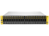
Fibre Channel cables connect the ports in the drive cage to the ports on the controller nodes. Each cable is labeled to indicate the ports it uses. NOTE: Daisy chaining is not supported for the DC4 drive cages. Figure 17 DC4 Drive Cage Table 7 DC4 Drive Cage Components Item Description 1 FC-AL Port B0 2 FC-AL Port A0 3 FC-AL Modules 4 FC-AL Port A1 5 FC-AL Port B1 DC3 Drive Cage and Ports and Cabling The DC3 drive cage contains 16 drive bays at the front, each accommodating the appropriate plug-in drive magazine module. The 16 drive bays are arranged in four rows of four drives. Figure 18 (page 65) shows the front view of a DC3 drive cage. Figure 18 DC3 Drive Cage (Front View) Drive Cage/Enclosure Models 65
-
 1
1 -
2
-
3
-
4
-
5
-
6
-
7
-
8
-
9
-
10
-
11
-
12
-
13
-
14
-
15
-
16
-
17
-
18
-
19
-
20
-
21
-
22
-
23
-
24
-
25
-
26
-
27
-
28
-
29
-
30
-
31
-
32
-
33
-
34
-
35
-
36
-
37
-
38
-
39
-
40
-
41
-
42
-
43
-
44
-
45
-
46
-
47
-
48
-
49
-
50
-
51
-
52
-
53
-
54
-
55
-
56
-
57
-
58
-
59
-
 60
60 -
 61
61 -
 62
62 -
 63
63 -
 64
64 -
 65
65 -
 66
66 -
 67
67 -
 68
68 -
 69
69 -
 70
70 -
71
-
72
-
73
-
74
-
75
-
76
-
77
-
78
-
79
-
80
-
81
-
82
-
83
-
84
-
85
-
86
-
87
-
88
-
89
-
90
-
91
-
92
-
93
-
94
-
95
 |
 |

Fibre Channel cables connect the ports in the drive cage to the ports on the controller nodes. Each
cable is labeled to indicate the ports it uses.
NOTE:
Daisy chaining is not supported for the DC4 drive cages.
Figure 17 DC4 Drive Cage
Table 7 DC4 Drive Cage Components
Description
Item
FC-AL Port B0
1
FC-AL Port A0
2
FC-AL Modules
3
FC-AL Port A1
4
FC-AL Port B1
5
DC3 Drive Cage and Ports and Cabling
The DC3 drive cage contains 16 drive bays at the front, each accommodating the appropriate
plug-in drive magazine module. The 16 drive bays are arranged in four rows of four drives.
Figure 18 (page 65)
shows the front view of a DC3 drive cage.
Figure 18 DC3 Drive Cage (Front View)
Drive Cage/Enclosure Models
65