HP 3PAR StoreServ 7450 2-node HP 3PAR StoreServ Storage Concepts Guide (OS 3.1 - Page 68
HP 3PAR StoreServ 10000 Controller Node Numbering, HP 3PAR StoreServ 7200 Storage System
 |
View all HP 3PAR StoreServ 7450 2-node manuals
Add to My Manuals
Save this manual to your list of manuals |
Page 68 highlights
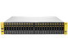
Figure 20 HP 3PAR StoreServ 7200 Storage System Figure 21 HP 3PAR StoreServ 7400 Storage System (4 Nodes) HP 3PAR StoreServ 10000 Controller Node Numbering The HP 3PAR StoreServ 10000 system may contain two, four, six or eight controller nodes per system configuration. The controller node chassis is located at the rear of the storage cabinet. From the rear of the storage cabinet, component numbering starts with zero (0) at the bottom-left corner and advances right and upward. For example, the node in the lower left position is identified as node 0 and the adjacent node (right) is identified as node 1. When two node chassis are present, the orientation of the lower and upper nodes becomes inverted. The node located in upper right corner of a StoreServ 10000 with 8 nodes is identified as node 7. The following figure shows the numbering and positioning of the controller nodes in a StoreServ 10000 chassis. The 4-node model is shown on the left; the 8-node model is shown on the right. 68 HP 3PAR Storage System Hardware
-
 1
1 -
2
-
3
-
4
-
5
-
6
-
7
-
8
-
9
-
10
-
11
-
12
-
13
-
14
-
15
-
16
-
17
-
18
-
19
-
20
-
21
-
22
-
23
-
24
-
25
-
26
-
27
-
28
-
29
-
30
-
31
-
32
-
33
-
34
-
35
-
36
-
37
-
38
-
39
-
40
-
41
-
42
-
43
-
44
-
45
-
46
-
47
-
48
-
49
-
50
-
51
-
52
-
53
-
54
-
55
-
56
-
57
-
58
-
59
-
60
-
61
-
62
-
 63
63 -
 64
64 -
 65
65 -
 66
66 -
 67
67 -
 68
68 -
 69
69 -
 70
70 -
 71
71 -
 72
72 -
 73
73 -
74
-
75
-
76
-
77
-
78
-
79
-
80
-
81
-
82
-
83
-
84
-
85
-
86
-
87
-
88
-
89
-
90
-
91
-
92
-
93
-
94
-
95
 |
 |
