HP 4400 HP Controller Enclosure LED Display Replacement Instructions (593093-0
HP 4400 Manual
 |
View all HP 4400 manuals
Add to My Manuals
Save this manual to your list of manuals |
HP 4400 manual content summary:
- HP 4400 | HP Controller Enclosure LED Display Replacement Instructions (593093-0 - Page 1
HP Controller Enclosure LED Display Replacement Instructions About this document For the latest documentation, go to http://www.hp.com/support/ manuals, and select your product. The information contained herein is subject to change without notice. The only warranties for HP products and services - HP 4400 | HP Controller Enclosure LED Display Replacement Instructions (593093-0 - Page 2
LED display 1. Power down the controller enclosure with HP P6000 Command View or the P6000 WOCP. Powering down the controller enclosure also removes power from the disk enclosures. To power down with HP P6000 Command View: a. In the navigation pane, select your storage system. b. In the Initialized - HP 4400 | HP Controller Enclosure LED Display Replacement Instructions (593093-0 - Page 3
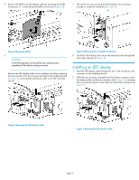
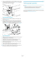
Figure 6 Removing the array LED membrane . 8. Lift off the LED display and remove the attached cable through the slot in the enclosure (2, Figure 6). Installing an LED display 1. Feed the LED display cable through the slot in the enclosure to the connector on the midplane board. 2. With the top - HP 4400 | HP Controller Enclosure LED Display Replacement Instructions (593093-0 - Page 4
the enclosure front bezel. 8. Reattach all cables (Fibre Channel and/or SAS, Ethernet, power) to the enclosure components. 9. Power up attached disk enclosures by pressing the power button on the rear power UID bezel of each disk enclosure. 10. Power up the controller enclosure by pressing the power
-
 1
1 -
 2
2 -
 3
3 -
 4
4
 |
 |

HP Controller Enclosure LED
Display Replacement Instructions
© Copyright 2009 Hewlett-Packard Development Company, L.P.
Second edition: May 2011
The information in this document is subject to change without notice.
Printed in Puerto Rico
www.hp.com
*593093-001*
About this document
For the latest documentation, go to
h
t
tp://w
w
w
.hp
.co
m/su
ppo
r
t/
man
uals
, and select your product.
The information contained herein is subject to change without notice.
The only warranties for HP products and services are set forth in the
express warranty statements accompanying such products and services.
Nothing herein should be construed as constituting an additional
warranty. HP shall not be liable for technical or editorial errors or
omissions contained herein.
WARRANTY STATEMENT:
To obtain a copy of the warranty for this product, see the warranty
information website:
h
t
tp://w
w
w
.hp
.co
m/go/s
t
o
r
age
w
ar
r
an
t
y
Before you begin
Observe the following precautions when replacing the LED display.
CAUTION:
When removing the LED display cable from the midplane board
connector, lift up on the top of the connector just enough to
disengage the cable. Do not attempt to completely remove the
top connector from the bottom mating connector.
Parts can be damaged by electrostatic discharge. Use proper
anti-static protection. Refer to the documentation that shipped
with your system for additional information.
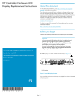
The LED display is located under the front bezel (see
Figure 1
).
1. LED display
Figure 1 Front LED display location
.
Your controller enclosure module may vary slightly from what is illustrated
in this document.
Page 1