HP 4400 HP Controller Enclosure LED Display Replacement Instructions (593093-0 - Page 2
Verifying component failure, Removing an LED display
 |
View all HP 4400 manuals
Add to My Manuals
Save this manual to your list of manuals |
Page 2 highlights
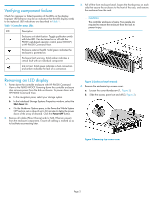
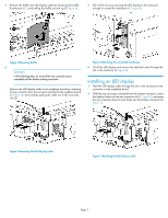
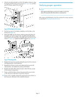
Verifying component failure Check for improper or failed operation of the LEDs on the display. Improper LED behavior may be an indication that the LED display needs to be replaced. LED indications are described in Table 1. Table 1 Controller status LEDs LED Description Enclosure unit identification. Toggle pushbutton switch with blue LED. Can be turned on or off with the P6000 web-based operator control panel (WOCP) or HP P6000 Command View. Enclosure external health. Solid green indicates the enclosure is powered on. Enclosure fault warning. Solid amber indicates a critical fault with an individual component. Link to host. Solid green indicates a host connection and amber indicates the lack of a connection. 3. Pull off the front enclosure bezel, loosen the thumbscrews on each side that secure the enclosure to the front of the rack, and remove the enclosure from the rack. CAUTION: The controller enclosure is heavy. Two people are required to remove the enclosure from the rack to prevent injury. Removing an LED display 1. Power down the controller enclosure with HP P6000 Command View or the P6000 WOCP. Powering down the controller enclosure also removes power from the disk enclosures. To power down with HP P6000 Command View: a. In the navigation pane, select your storage system. b. In the Initialized Storage Systems Properties window, select the Shut down tab. c. On the Shutdown Options pane, in the Power the Whole System OFF section, set a value of up to 60 minutes to delay the power down of the array (if desired). Click the Power OFF button. 2. Remove all cables (Fibre Channel and/or SAS, Ethernet, power) from the enclosure components. Ensure all cabling is marked so as to facilitate reconnecting later. Figure 2 Enclosure bezel removal . 4. Remove the enclosure top access cover: a. Loosen the cover thumbscrew (1, Figure 3). b. Slide the access panel out and off (2, Figure 3). Figure 3 Removing top access cover . Page 2
-
 1
1 -
 2
2 -
 3
3 -
 4
4
 |
 |
