HP 4400 HP StorageWorks Controller Enclosure 4Gb Array Controller Replacement - Page 2
Verifying component failure, Removing a controller
 |
View all HP 4400 manuals
Add to My Manuals
Save this manual to your list of manuals |
Page 2 highlights
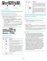
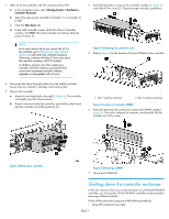
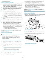
1. Controller 1 Figure 1 Controller locations . 2. Controller 2 Verifying component failure Use the following methods to verify component failure: • Analyze any failure messages received. Fault monitoring software from HP provides a recommended solution. • Check status using HP Command View EVA: 1. In the navigation pane, select Storage system > Hardware > Controller Enclosure > Controller. 2. The status is displayed in the Condition/State field. An operational state of (Failed) would indicate a fault that may require a replacement. 3. To help identify the correct controller, click Locate > Locate On. This causes the blue UID indicator to light on the controller module at the rear of the controller enclosure. • Check the controller status LEDs as shown in Figure 2 and Table 1. Item LED 5 6 Indication Green LED that indicates write-back cache status. Slow flashing green LED indicates standby power. Solid green LED indicates cache is good with normal AC power applied. Amber LED that indicates DIMM status. The LED is off when DIMM status is good. Slow flashing amber indicates cache/DIMMs are being powered by battery (during AC power loss). Solid amber indicates a DIMM failure. Removing a controller CAUTION: Verify which controller is being serviced. Removing the wrong controller can cause data loss. Consider the following: • Replacement controllers do not have DIMM modules, therefore the DIMMs from the controller being removed must be transferred to the replacement controller. • HP recommends that you replace the controller while the controller enclosure is powered on to ensure the controller software on the redundant controller is copied to the replaced controller. Figure 2 Controller status LEDs . Table 1 Controller status LEDs Item LED Indication 1 Blue LED used to identify a specific controller module within the enclosure. 2 Controller health OK. Flashing green during boot. Solid green LED after boot. Flashing amber indicates a controller crash or the system is inoperative and attention is required. Solid amber indicates that the 3 controller cannot reboot and should be replaced. If both the solid amber and solid blue LEDs are lit, the controller has com- pleted a warm removal procedure, and can be safely swapped. 4 N/A (top right) Not used. IMPORTANT: Do not insert the replacement controller while the system is down. Doing so can disconnect the controller's write-back cache, which will clear cache memory of possibly unsaved data. Further, do not install a replacement controller while the system is powered off or halted; this can cause unpredictable XCS controller software upgrades or downgrades. Because a powered-off controller enclosure always starts with the controller software version of the controller in slot 1, be absolutely sure that the controller software of the controller in slot 1 matches that of the replacement controller. If you are replacing the controller in slot 1 in a powered-off controller enclosure or the controller in slot 2 is halted and the controller software versions do not match, this can lead to an inadvertent controller software upgrade or downgrade of the array, and potentially the loss of data when metadata is overwritten. If the controller software version of the operating controller is unknown and the controller enclosure is powered off, HP recommends that you start the array with only the operating controller installed and verify the controller software version before replacing the partner controller. Page 2
-
 1
1 -
 2
2 -
 3
3 -
 4
4 -
 5
5
 |
 |
