HP 6120G/XG HP ProCurve 6120XG Blade Switch Installation Instructions - Page 1
HP 6120G/XG Manual
 |
View all HP 6120G/XG manuals
Add to My Manuals
Save this manual to your list of manuals |
Page 1 highlights
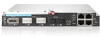
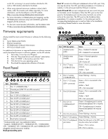
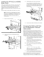
HP ProCurve 6120XG Blade Switch Installation Instructions for HP c-Class BladeSystem Overview This card provides instructions for installing an HP ProCurve 6120XG Blade Switch for c-Class BladeSystem in an HP c-Class BladeSystem enclosure. Kit contents HP ProCurve 6120XG Blade Switch Console cable (USB A to USB mini-AB) Customer Support/Warranty booklet License documentation This document IMPORTANT: Only use HP-approved pluggable SFP+ or SFP optical transceiver modules or SFP+ direct attach cables. For more information, see the QuickSpecs on the HP website (http://www.hp.com/go/bladesystem/interconnects). HP ProCurve 6120XG Blade Switch © Copyright 2009 Hewlett-Packard Development Company, L.P. The information contained herein is subject to change without notice. The only warranties for HP products and services are set forth in the express warranty statements accompanying such products and services. Nothing herein should be construed as constituting an additional warranty. HP shall not be liable for technical or editorial errors or omissions contained herein. Microsoft is a U.S. registered trademark of Microsoft Corporation. Part Number 539957-001 September 2009 (First Edition) Additional information For more information on the association between the server blade mezzanine connectors and the interconnect bays, see the HP BladeSystem enclosure setup and installation guide that ships with the enclosure. During server blade installation, the location of the mezzanine card determines the installation location of the switch modules. For specific switch port connection information for each blade, see the HP BladeSystem enclosure setup and installation guide that ships with the enclosure. Connections differ by blade type. Installation guidelines Observe the following guidelines: All HP ProCurve switches in the enclosure require valid and unique IP addresses before they can be accessed via Ethernet. By default DHCP is enabled on these switches, so the switch management interface can get IP credentials from the DHCP server on the attached Ethernet network. If EBIPA is enabled on the Onboard Administrator (OA) of the enclosure, OA will assign an IP address to the switch from its configured IP address range, so that switch can be accessed from the OA Ethernet interface. If EBIPA is disabled but DHCP service is available on the network attached to the OA Ethernet interface, then the switch gets its IP address assigned from the attached network. Any IP host on that network can access the switch at this point. If the DHCP service is not available on the attached network, the user can assign valid IP credentials from the
-
 1
1 -
 2
2 -
 3
3 -
 4
4
 |
 |