HP 6400/8400 HP StorageWorks power UID replacement instructions (533484-001, M - Page 3
Installing the power UID, Verifying proper operation
 |
View all HP 6400/8400 manuals
Add to My Manuals
Save this manual to your list of manuals |
Page 3 highlights
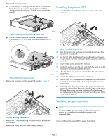
4. Remove the top access cover. a. For the MSA6X/7X and EVA disk enclosures: Lift the access panel latch (1, Figure 3). The access panel will slightly disengage from the enclosure. Slide the access panel to the rear (2). 1 2 Installing the power UID 1. Insert the LED bezel into the slot at the rear of the enclosure (1, Figure 6). 15818 Figure 3 Removing disk enclosure top access cover b. For the EVA4400 controller enclosure: Loosen the cover thumbscrew (1, Figure 4). Slide the access panel out and off (2). 2 1 3 1 2 15778 Figure 4 Removing top access cover 5. Remove the connector from the power UID board (1, Figure 5). 2 3 1 15807 Figure 6 Installing the power UID 2. Align the board on the enclosure and secure the board and bezel ring with a T-15 screw (2). 3. Plug the UID cable from the midplane board (on disk enclosures) or riser card (on controller enclosure) into the connector on the UID board (3). 4. Secure the top access panel on the enclosure. 5. Reinstall the enclosure into the rack, and attach the bezel ears (disk enclosure) or front bezel (controller enclosure). 6. If the disk drives were previously removed from the disk enclosure, reinsert them. 7. Reattach the cabling to the enclosure components. 8. Press the Power On/Standby button on the power UID bezel (located at rear of enclosure) and hold it down long enough to power up the enclosure. 9. For the EVA only: Power up any other disk enclosures attached to the array by pressing their Power On/Standby button on the power UID bezel. After power has been applied to all disk enclosures, then apply power on the controller enclosure using the power button on the power UID bezel. Verifying proper operation 15806 Figure 5 Removing the power UID 6. Remove the T-15 screw securing the board and LED bezel to the enclosure (2). 7. Remove the board, and then remove the LED bezel (3). NOTE: After powering up, wait one minute for a disk enclosure or three minutes for a controller enclosure for the system to check component status. Check all LEDs on the power UID for proper illumination. Page 3
-
 1
1 -
 2
2 -
 3
3
 |
 |
