HP 6730b HP Compaq 6735b Notebook PC and HP Compaq 6730b Notebook PC - Mainten - Page 94
ExpressCard board, Remove the TouchPad assembly
 |
UPC - 884420990376
View all HP 6730b manuals
Add to My Manuals
Save this manual to your list of manuals |
Page 94 highlights
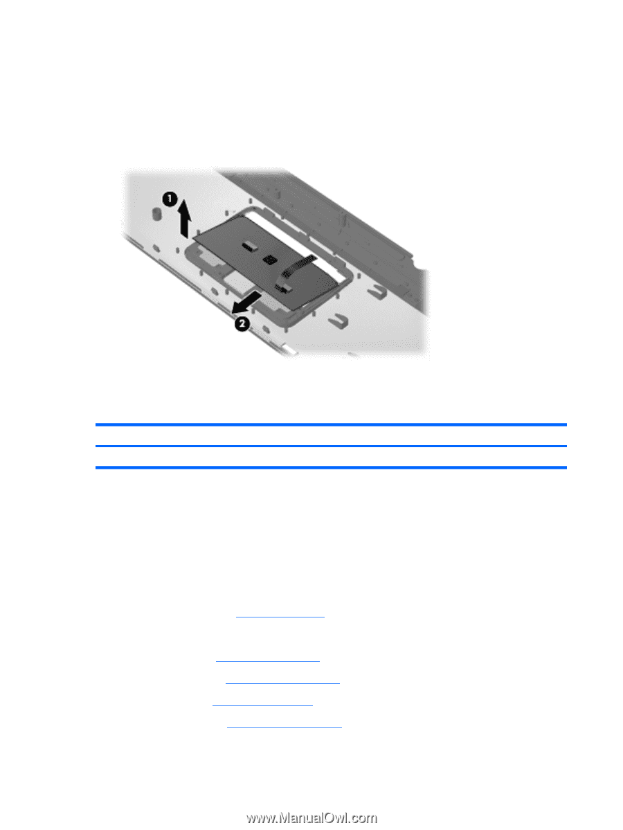
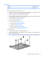
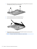
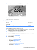
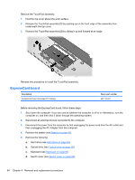
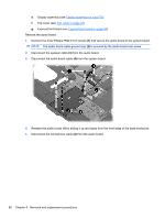
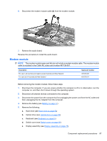
Remove the TouchPad assembly: 1. Hold the top cover above the work surface. 2. Release the TouchPad assembly (1) by pushing up on the front edge of the assembly from underneath the top cover. 3. Remove the TouchPad assembly (2) by sliding it up and forward at an angle Reverse this procedure to install the TouchPad assembly. ExpressCard board Description ExpressCard board (includes RTC battery) Spare part number 487119-001 Before removing the ExpressCard board, follow these steps: 1. Shut down the computer. If you are unsure whether the computer is off or in Hibernation, turn the computer on, and then shut it down through the operating system. 2. Disconnect all external devices connected to the computer. 3. Disconnect the power from the computer by first unplugging the power cord from the AC outlet and then unplugging the AC Adapter from the computer. 4. Remove the battery (see Battery on page 47). 5. Remove the following: a. Hard drive (see Hard drive on page 53) b. Optical drive (see Optical drive on page 56) c. Keyboard (see Keyboard on page 61) d. Switch cover (see Switch cover on page 66) 84 Chapter 4 Removal and replacement procedures
-
 1
1 -
2
-
3
-
4
-
5
-
6
-
7
-
8
-
9
-
10
-
11
-
12
-
13
-
14
-
15
-
16
-
17
-
18
-
19
-
20
-
21
-
22
-
23
-
24
-
25
-
26
-
27
-
28
-
29
-
30
-
31
-
32
-
33
-
34
-
35
-
36
-
37
-
38
-
39
-
40
-
41
-
42
-
43
-
44
-
45
-
46
-
47
-
48
-
49
-
50
-
51
-
52
-
53
-
54
-
55
-
56
-
57
-
58
-
59
-
60
-
61
-
62
-
63
-
64
-
65
-
66
-
67
-
68
-
69
-
70
-
71
-
72
-
73
-
74
-
75
-
76
-
77
-
78
-
79
-
80
-
81
-
82
-
83
-
84
-
85
-
86
-
87
-
88
-
 89
89 -
 90
90 -
 91
91 -
 92
92 -
 93
93 -
 94
94 -
 95
95 -
 96
96 -
 97
97 -
 98
98 -
 99
99 -
100
-
101
-
102
-
103
-
104
-
105
-
106
-
107
-
108
-
109
-
110
-
111
-
112
-
113
-
114
-
115
-
116
-
117
-
118
-
119
-
120
-
121
-
122
-
123
-
124
-
125
-
126
-
127
-
128
-
129
-
130
-
131
-
132
-
133
-
134
-
135
-
136
-
137
-
138
-
139
-
140
-
141
-
142
-
143
-
144
-
145
-
146
-
147
-
148
-
149
-
150
-
151
-
152
-
153
-
154
-
155
-
156
-
157
-
158
-
159
-
160
-
161
-
162
-
163
-
164
-
165
-
166
-
167
-
168
-
169
-
170
-
171
-
172
-
173
-
174
-
175
-
176
 |
 |