HP 70 MSA7X Series Enclosure Midplane Replacement Instructions (436512-001, Fe - Page 2
Removing the midplane
 |
View all HP 70 manuals
Add to My Manuals
Save this manual to your list of manuals |
Page 2 highlights
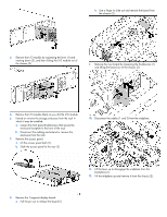
Hard drive LED combinations Online/activity LED Fault/UID LED (green) (amber/blue) Flashing regularly Amber, flashing (1 Hz) regularly (1 Hz) Flashing regularly Off (1 Hz) Flashing irregularly Amber, flashing regularly (1 Hz) Flashing irregularly Off Off Steadily amber Off Amber, flashing regularly (1 Hz) Off Off Interpretation Do not remove the drive. Removing a drive may terminate the current operation and cause data loss. The drive is part of an array that is undergoing capacity expansion or a stripe size migration, but a predictive failure alert has been received for this drive. To minimize the risk of data loss, do not replace the drive until the expansion or migration is complete. Do not remove the drive. Removing a drive may terminate the current operation and cause data loss. The drive is rebuilding, or it is part of an array that is undergoing capacity expansion or a stripe size migration. The drive is active, but a predictive failure alert has been received for this drive. Replace the drive as soon as possible. The drive is active and it is operating normally. A critical fault condition has been identified for this drive and the controller has placed it offline. Replace the drive as soon as possible. A predictive failure alert has been received for this drive. Replace the drive as soon as possible. The drive is offline, a spare, or not configured as part of an array. I/O module and system fan LEDs Item Description I/O module LED Green = System activity Amber = Fault condition Off = No system activity System fan LED Green = Normal operation Amber = Fault condition Off = Fan unseated from connector or failed Removing the midplane To remove the midplane: 1. Power down the enclosure: a. Power down any attached servers. See the server documentation. b. Press the Power On/Standby button on the enclosure. c. Wait for the system power LED to go from green to amber. d. Disconnect the power cords. CAUTION: Be sure that the server is the first unit to be powered down and the last to be powered back up. Taking this precaution ensures that the system does not erroneously mark the drives as failed when the server is powered up. 2. Remove the power supplies by disconnecting the power cord from each supply, pressing the lever inward (1) and sliding the component out of the chassis (2). 3. Remove the system fans by pressing up on the lever on each fan (1) and sliding the fan out of the chassis (2).
-
 1
1 -
 2
2 -
 3
3 -
 4
4
 |
 |
