HP 9040 HP LaserJet 9040mfp/9050mfp - (multiple language) Getting Started Guid - Page 18
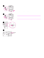
Step 6. Position the product, right. The shipping lock is located on the left side of the scanner.
 |
UPC - 829160792927
View all HP 9040 manuals
Add to My Manuals
Save this manual to your list of manuals |
Page 18 highlights
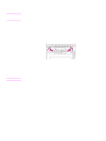
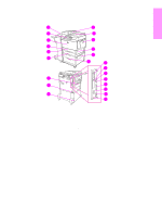
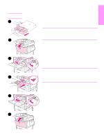
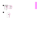
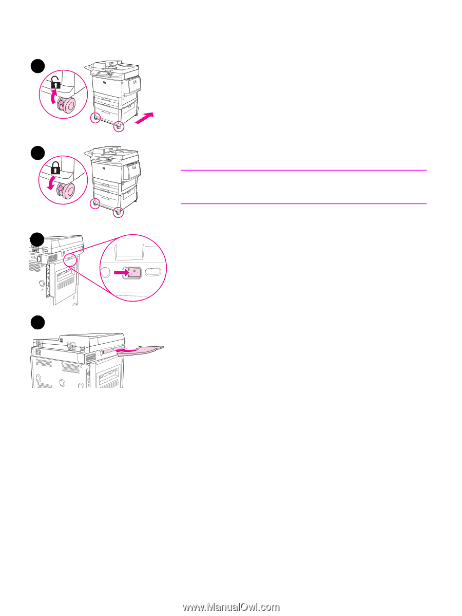
Step 6. Position the product 1 1 Unlock the front wheels of the product (if they are locked), and roll the product to its permanent location. Leave space to walk behind the product and to install the output device. 2 Push the locking tabs on the front wheels to the lock position. Only the front wheels lock. 3 If the ADF output bin is installed, remove it. 4 Make sure that the scanner shipping lock is unlocked (moved to the right). The shipping lock is located on the left side of the scanner. 2 5 Attach the ADF output bin. Note You must position the product before you install the output device. See Step 8. Install output device. 4 5 16 Product Setup ENWW
-
 1
1 -
2
-
3
-
4
-
5
-
6
-
7
-
8
-
9
-
10
-
11
-
12
-
 13
13 -
 14
14 -
 15
15 -
 16
16 -
 17
17 -
 18
18 -
 19
19 -
 20
20 -
 21
21 -
 22
22 -
 23
23 -
24
-
25
-
26
-
27
-
28
-
29
-
30
-
31
-
32
-
33
-
34
-
35
-
36
-
37
-
38
-
39
-
40
-
41
-
42
-
43
-
44
-
45
-
46
-
47
-
48
-
49
-
50
-
51
-
52
-
53
-
54
-
55
-
56
-
57
-
58
-
59
-
60
-
61
-
62
-
63
-
64
-
65
-
66
-
67
-
68
-
69
-
70
-
71
-
72
-
73
-
74
-
75
-
76
-
77
-
78
-
79
-
80
-
81
-
82
-
83
-
84
-
85
-
86
-
87
-
88
-
89
-
90
-
91
-
92
-
93
-
94
-
95
-
96
-
97
-
98
-
99
-
100
-
101
-
102
-
103
-
104
-
105
-
106
-
107
-
108
-
109
-
110
-
111
-
112
-
113
-
114
-
115
-
116
-
117
-
118
-
119
-
120
-
121
-
122
-
123
-
124
-
125
-
126
-
127
-
128
-
129
-
130
-
131
-
132
-
133
-
134
-
135
-
136
-
137
-
138
-
139
-
140
-
141
-
142
-
143
-
144
-
145
-
146
-
147
-
148
-
149
-
150
-
151
-
152
-
153
-
154
-
155
-
156
-
157
-
158
-
159
-
160
-
161
-
162
-
163
-
164
-
165
-
166
-
167
-
168
-
169
-
170
-
171
-
172
-
173
-
174
-
175
-
176
-
177
-
178
-
179
-
180
-
181
-
182
-
183
-
184
-
185
-
186
-
187
-
188
-
189
-
190
-
191
-
192
-
193
-
194
-
195
-
196
-
197
-
198
-
199
-
200
-
201
-
202
-
203
-
204
-
205
-
206
-
207
-
208
-
209
-
210
-
211
-
212
-
213
-
214
-
215
-
216
-
217
-
218
-
219
-
220
-
221
-
222
-
223
-
224
-
225
-
226
-
227
-
228
-
229
-
230
-
231
-
232
-
233
-
234
-
235
-
236
-
237
-
238
-
239
-
240
-
241
-
242
-
243
-
244
-
245
-
246
-
247
-
248
-
249
-
250
-
251
-
252
-
253
-
254
-
255
-
256
-
257
-
258
-
259
-
260
-
261
-
262
-
263
-
264
-
265
-
266
-
267
-
268
-
269
-
270
-
271
-
272
-
273
-
274
-
275
-
276
-
277
-
278
-
279
-
280
-
281
-
282
-
283
-
284
-
285
-
286
-
287
-
288
 |
 |
16
Product Setup
ENWW
Step 6.
Position the product
1
Unlock the front wheels of the product (if they are locked), and roll
the product to its permanent location. Leave space to walk behind
the product and to install the output device.
2
Push the locking tabs on the front wheels to the lock position. Only
the front wheels lock.
3
If the ADF output bin is installed, remove it.
4
Make sure that the scanner shipping lock is unlocked (moved to the
right). The shipping lock is located on the left side of the scanner.
5
Attach the ADF output bin.
Note
You must position the product before you install the output device. See
Step 8.
Install output device
.
1
2
4
5