HP A3550A Battery Backup Unit Installation Guide (20-slot)
HP A3550A - High Availability Disk Arrays Model 20 Storage Enclosure Manual
 |
View all HP A3550A manuals
Add to My Manuals
Save this manual to your list of manuals |
HP A3550A manual content summary:
- HP A3550A | Battery Backup Unit Installation Guide (20-slot) - Page 1
Hewlett-Packard Battery Backup Unit (BBU) Installation Guide (20-slot Disk Arrays) Hewlett-Packard BBUs are customer installable and replaceable. A replacement BBU must be the same type as the BBU being replaced. The - HP A3550A | Battery Backup Unit Installation Guide (20-slot) - Page 2
switch to the LOCK position. For more information on BBU installation procedures and recharge times, see the (EWLETT 0ACKARD (IGH !VAILABILITY 3#3) $ISK !RRAY 5SER 'UIDE. Manual Part Number A3232-90008 E0897 Copyright © 1997 Hewlett-Packard Company *PA3232-96026* A3232-96026
-
 1
1 -
 2
2
 |
 |
Hewlett-Packard Battery Backup Unit (BBU)
Installation Guide (20-slot Disk Arrays)
Hewlett-Packard BBUs are customer installable and replaceable. A replacement BBU must be the same type as the BBU
being replaced.
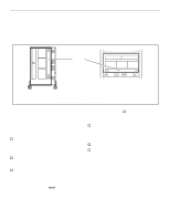
The locations of the BBUs in the 20-slot disk arrays are shown in Figure 1.
.
Figure 1.
Install or replace a BBU by performing the following steps. Place a check in the appropriate
o
as the step is completed.
Step 1:
Observe antistatic precautions
A BBU is shipped with an ESD kit containing:
–
ESD wrist strap
–
ESD conductive sheet
o
Ground the ESD wrist strap to any unplated metal on
the disk array chassis and fasten the strap to your wrist.
Step 2:
Prepare to install the BBU
o
Remove the new BBU from its shipping carton and
place it on a suitable antistatic surface or the ESD
conductive sheet.
o
Open the fan pack by sliding the LOCK/UNLOCK switch
to the UNLOCK position and carefully swinging the fan
pack open.
The BBU can be installed or replaced with array power on.
The installation or replacement
MUST
be completed and the
fan pack closed within two minutes to avoid a thermal shut-
down.
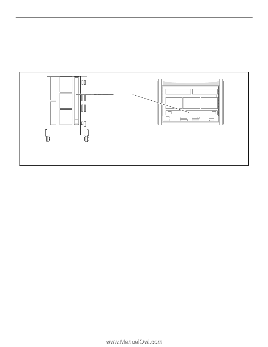
Step 3: Install the BBU
o
Locate the slot where the BBU is to be installed (Figure
1) and remove the failed BBU or the BBU filler panel if
present (Figure 2). To remove the BBU, slide the black
latches toward the center of the unit and extract the
BBU.
o
Install the BBU as shown in Figure 2.
o
Push the BBU into the disk array chassis until the
latches on the BBU lock and audible clicks are heard.
When the latches are locked, the BBU cannot be pulled
out again without using the latches.
BBU
20-slot deskside and rackmount disk arrays (rear view)
(shown with fan packs removed for clarity)