HP A3550A Power Supply Installation Guide - Not Orderable - Page 1
HP A3550A - High Availability Disk Arrays Model 20 Storage Enclosure Manual
 |
View all HP A3550A manuals
Add to My Manuals
Save this manual to your list of manuals |
Page 1 highlights
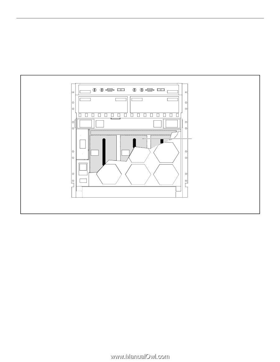
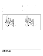
Hewlett-Packard Power Supply Installation Guide Hewlett-Packard power supplies are installable and replaceable. A replacement or add-on power supply must be the same type as the power supplies already installed in the array. The locations of the power supplies in the 30-slot disk arrays are shown in Figure 1. . Power supply Disk array rear view Figure 1. Install a power supply by performing the following steps. Place a check in the appropriate o as the step is completed. Step 1: Observe antistatic precautions A power supply is shipped with an ESD kit containing: - ESD wrist strap - ESD conductive sheet o Ground the ESD wrist strap to any unplated metal on the disk array chassis and fasten the strap to your wrist. On 30-slot disk arrays, the ESD wrist strap can be grounded to the metal edge above the rear retaining screws. Step 2: Prepare to install the power supply o Remove the new power supply from its shipping carton and place it on a suitable antistatic surface or the ESD conductive sheet. o Press the release button on the fan pack and carefully swing the fan pack down. The installation or removal and replacement MUST be completed and the fan pack closed within two minutes or the disk array will perform a thermal shutdown.
-
 1
1 -
 2
2
 |
 |