HP AD510A HP StorageWorks MSA1500 cs Fibre Channel I/O Module Replacement Inst - Page 2
Step 1: Removing the SFP transceiver
 |
UPC - 829160218625
View all HP AD510A manuals
Add to My Manuals
Save this manual to your list of manuals |
Page 2 highlights
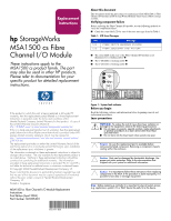
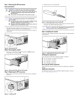
Step 1: Removing the SFP transceiver Laser precautions WARNING: To reduce the risk of injury from laser radiation or damage to the equipment, observe the following precautions: ■ Do not open any panels, operate controls, make adjustments, or perform procedures to a laser device other than those specified herein. ■ Do not stare into the laser beam when panels are open. Caution: Use appropriate precautions when handling Fibre Channel cables: ■ Touching the end of a Fibre Channel cable will either damage the cable or cause performance problems, including intermittent difficulties accessing the storage. ■ Whenever a Fibre Channel cable is not connected, replace the protective covers on the ends of the cable. 1. Press the release clip on the left of the cable connector to remove the Fibre Channel I/O cable from the back of the failed transceiver. 2. Pull the release tab on the transceiver and pull the transceiver straight out of the device. 2. Remove the dust cover from the SFP. Figure 5: Removing the dust cover from the SFP 3. Insert the Fibre Channel I/O cable, with the clip side to the left, into the transceiver. The cable should snap into place. Caution: To reduce the risk of damage to the equipment, do not use excessive force when inserting the transceiver. Step 4: Installing the module To install the Fibre Channel I/O module, slide it into the bay until the module clicks into place. Figure 2: Removing the SFP Step2: Removing the module 3. Lift the port-colored Fibre Channel I/O module latch 1 and pull the I/O module out of the enclosure 2. 2 1 Figure 3: Removing the Fibre Channel I/O module Step 3: Replacing the SFP transceiver 1. With the plastic tab facing to the right, insert the transceiver straight into the device. Figure 6: Installing the Fibre Channel I/O module Verifying the replacement After replacing the failed Fibre Channel I/O module, verify that: ■ No error messages are displayed on the LCD. ■ The status LED is solid green. ■ The 1-GB LED is solid green. ■ The 1-GB LED is solid green. Returning the failed component Please follow the return instructions provided in the replacement component package. Additional information For additional information, refer to the MSA technical documents web site at http://www.hp.com/go/msa1500cs. Figure 4: Installing a SFP
-
 1
1 -
 2
2
 |
 |
