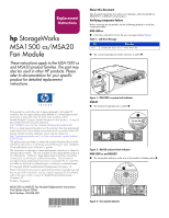
HP AD510A HP StorageWorks MSA1500 cs/MSA20 Fan Module Replacement Instructions - Page 2
Returning the failed component
 |
UPC - 829160218625
View all HP AD510A manuals
Add to My Manuals
Save this manual to your list of manuals |
Page 2 highlights
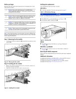
Before you begin Read the following cautions and information before beginning removal and replacement procedures. Caution: Be sure the replacement part is available before removing the failed component. Removing a component impacts cooling within the enclosure. Caution: Parts can be damaged by electrostatic discharge. Use proper anti-static protection. Refer to the documentation that shipped with your system for additional information. Caution: It is important to follow these instructions when replacing components in the MSA. If the procedure is done improperly, it is possible to lose data or damage equipment. Caution: Before replacing this hot-pluggable component ensure that steps have been taken to prevent loss of data. Note: Some of the illustrations in this document may show a different unit. However, the replacement instructions are the same for all units in the MSA family using this component. Step 1: Removing the fan module 1. Lift the port-colored fan module latch 1 and pull the fan module out of the enclosure 2. 2 1 Figure 4: Removing the fan module Step 2: Installing the fan module 1. Remove any connector protector that may be covering the connector on the front of the new fan module. 2. Slide the fan module into the bay until it clicks into place. Verifying the replacement After replacing the failed fan module verify that: MSA1500 cs ■ Check the controller LCD for the message listed in Figure 2. Table 2: LCD Verification Message No. 400 Message STORAGE BOX # FAN OK ■ The MSA1500 cs system fault indicator is off (Figure 1, 1). ■ The heartbeat LED is flashing green 1. 1 Figure 6: Heartbeat LED MSA20 ■ The MSA20 enclosure fault indicator is no longer illuminated (Figure 2, 1). MSA1500 cs and MSA20 ■ The fan module indicator on the rear of the module is solid green (Figure 3, 1). Returning the failed component Please follow the return instructions provided in the replacement component package. Additional information For additional information on the MSA1500 cs, refer to the MSA technical documents web site at http://www.hp.com/go/msa1500cs. For additional information on the MSA20, refer to the MSA technical documents web site at http://www.hp.com/go/msa20. Figure 5: Installing the fan module
-
 1
1 -
 2
2
 |
 |
