HP AE326A HP StorageWorks 1500/1510i Modular Smart Array chassis replacement i - Page 1
HP AE326A - StorageWorks Modular Smart Array 1500 SAN SATA Starter Manual
 |
UPC - 882780184954
View all HP AE326A manuals
Add to My Manuals
Save this manual to your list of manuals |
Page 1 highlights
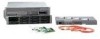
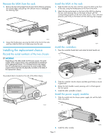
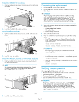
HP StorageWorks 1500/1510i Modular Smart Array chassis replacement instructions © Copyright 2004-2006 Hewlett-Packard Development Company, L.P. Second edition (December 2006) The information in this document is subject to change without notice. Printed in Singapore. www.hp.com About this document This document details procedures for replacing a failed MSA1500 or MSA1510i chassis. When replacing a chassis, components are removed from the failed chassis and then installed in the replacement. Components that are moved include the following: • Fibre Channel (or Ethernet) I/O modules • Fan modules • SCSI I/O modules • Power supply modules • Controllers • Blanks NOTE: The MSA1500 connects to the SAN with a Fibre Channel I/O module and the MSA1510i connects to the network with a 2-Port Ethernet I/O module. Illustrations in this document show the Fibre Channel I/O module of an MSA1500. If you are replacing an MSA1510i chassis, your module will look different. Before you begin Read the following cautions and notices before replacing the chassis. CAUTION: Parts can be damaged by electrostatic discharge. Use proper anti-static protection. For additional information, see the documentation that shipped with your system. CAUTION: Be sure to follow these instructions carefully. If the procedures are done improperly or out of sequence, it is possible to lose data or damage equipment. IMPORTANT: Schedule a maintenance window of approximately 60 minutes to complete this procedure. IMPORTANT: Before beginning these procedures, verify that there is a known, good backup of the system. Backup all volumes and, for the MSA1510i, record the iSCSI and Management settings. TIP: Before beginning these procedures, label all cables. This ensures that they are reconnected correctly. 364862-002 Page 1
-
 1
1 -
 2
2 -
 3
3 -
 4
4 -
 5
5
 |
 |