HP AP775A HP C-series Nexus 5000 Converged Network Switch quick start instruct
HP AP775A - Nexus Converged Network Switch 5010 Manual
 |
UPC - 884962062708
View all HP AP775A manuals
Add to My Manuals
Save this manual to your list of manuals |
HP AP775A manual content summary:
- HP AP775A | HP C-series Nexus 5000 Converged Network Switch quick start instruct - Page 1
instructions, download the Cisco Nexus 5000 Series Hardware Installation Guide and Cisco Nexus 5000 Series Switch CLI Software Configuration Guide from the Storage section of the HP website: http://www.hp.com/support/ manuals the telnet service? (yes/no) [y]: yes Enable the ssh service? (yes/no - HP AP775A | HP C-series Nexus 5000 Converged Network Switch quick start instruct - Page 2
system Do you want to continue? (y/n) [n] y The system is going down for reboot NOW! 3. Create a new VLAN. By default all ports are in VLAN 1. HP recommends that you use a different VLAN for FCoE. In this example you create a VLAN 200, allow access to Ethernet ports 1/1 to 1/20, and create virtual
-
 1
1 -
 2
2
 |
 |
HP C-series Nexus 5000 Converged Network
Switch quick start instructions
© Copyright 2009 Hewlett-Packard Development Company, L.P.
First edition: June 2009
The information in this document is subject to change without notice.
www.hp.com
5697-0043
1
Overview
Read these instructions to set up and configure the HP C-series Nexus 5000 Converged Network (CN)
Switch.
For the latest information on the C-series switches, including additional product information, supported SAN
configurations, related documentation, and software and firmware downloads, go to the following HP website
and select the C-series switch product of interest:
h
t
tp://h18
006
.w
w
w1.hp
.co
m/s
t
o
r
age/ne
t
w
o
r
king/
c_s
w
it
c
he
s/inde
x
.h
tml
.
For model-specific information or information about supported versions, see the HP Single Point of Connectivity
Knowledge (SPOCK) website:
h
t
tp://w
w
w
.hp
.co
m/s
t
o
r
age/s
poc
k
.
These instructions provide basic configuration steps. For detailed rack mount and configuration instructions,
download the
Cisco Nexus 5000 Series Hardware Installation Guide
and
Cisco Nexus 5000 Series Switch
CLI Software Configuration Guide
from the Storage section of the HP website:
h
t
tp://w
w
w
.hp
.co
m/su
ppo
r
t/
man
uals
.
Table 1
lists the Nexus 5000 CN components and part numbers.
Table 1 Nexus 5000 CN Components and Part Numbers
HP part number
Component
AP775A
HP Nexus 5010 Converged Network Switch
AP776A
HP Nexus 5020 Converged Network Switch
AP779A
HP Nexus 5000 8-port 4Gb FC Expansion Module
AP778A
HP Nexus 5000 4-port 4Gb FC + 4-port 10GbE Expansion Module
AP777A
HP Nexus 5000 6-port 10GbE Expansion Module
AP783A
HP 10GbE Short Range SFP+ Transceiver
AP784A
HP 3m C-series Passive Copper SFP+ Cable
AP785A
HP 5m C-series Passive Copper SFP+ Cable
For more information, see the
HP Nexus 5000 Converged Network Switch QuickSpecs
available at
h
t
tp:/
/h18
006
.w
w
w1.hp
.co
m/s
t
o
r
age/s
aninf
r
a
s
tr
u
c
tur
e/s
w
it
c
he
s/5
000ne
x
u
s/inde
x
.h
tml
.
Figure 1
and
Figure 2
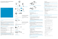
show sample SAN configurations with Nexus 5000 CN Switches.
Figure 3
and
Figure
4
show the port side of the Nexus 5020 and 5010, respectively;
Figure 5
and
Figure 6
show the non-port
side of the Nexus 5020 and 5010 respectively.
Figure 7
and
Figure 8
show the Nexus 5000 expansion
modules.
Figure 1 Sample configuration with Fibre Channel storage fabric attached to Nexus 5000 CN Switch
.
Figure 2 Sample configuration with Nexus 5000 CN Switch in a C-series SAN
.
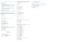
2. Ethernet connector with two cross-connect ports
on the left side and two network management1 (top)
and management2 (bottom) ports on the right side
1. System status LED
4. Slot 1 with 40 fixed 10-GbE ports
3. Console port
6. Slot 3 for an optional expansion module; shown
here with a 4–port FC plus a 4–port 10-GbE expan-
sion module
5. Slot 2 with an optional expansion module
7. AC power connectors
Figure 3 Nexus 5020 port side
.
2. Ethernet connector with two cross-connect ports
on the left side, and two network management1
(top) and management2 (bottom) ports on the right
side
1. System status LED
4. Slot 1 with 20 fixed 10-GbE ports
3. Console port
6. AC power connectors
5. Slot 2 for an optional expansion module; shown
here with a 4–port FC plus 4–port 10-GbE expan-
sion module
Figure 4 Nexus 5010 port side
.
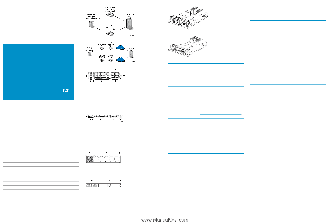
2. Five fan modules
1. Two power supplies
3. System status LED
Figure 5 Nexus 5020 non-port side
.
2. Two fan modules
1. Two power supplies
3. System status LED
Figure 6 Nexus 5010 non-port side
.
Figure 7 Nexus 5000 4–port 1/2/4–Gb Fibre Channel + 4–port 10–GbE expansion module
.
Figure 8 Nexus 5000 8–port 1/2/4–Gb Fibre Channel expansion module
.
2
Verify the carton contents
The carton contains the following:
•
One Nexus 5020 or Nexus 5010 CN Switch
•
Grounding lug kit and electrostatic discharge (ESD) wrist strap
•
Power cords
•
Rack mount kit
3
Verify the installation requirements
To set up the Nexus 5000 CN Switch for the first time, you will need the following:
•
A workstation with an installed terminal emulator (such as HyperTerminal)
•
An unused IP address and corresponding subnet mask and gateway address
•
A serial cable (supplied with the switch)
•
An Ethernet cable
•
Access to an FTP server to back up the switch configuration (optional)
•
Cisco branded SFP transceivers and compatible cables as specified in the
HP Nexus 5000 Converged
Network Switch QuickSpecs
, available at
h
t
tp://h18
006
.w
w
w1.hp
.co
m/s
t
o
r
age/s
aninf
r
a
s
tr
u
c
tur
e/
s
w
it
c
he
s/5
000ne
x
u
s/inde
x
.h
tml
.
4
Plan the site environment
Air flows through the Nexus 5000 CN Switch from front to back (port- side exhaust). You must maintain
ambient airflow throughout the data center to ensure normal operation. The ambient air temperature must
not exceed 40° C (104° F) and the ambient humidity (relative humidity, noncondensing) must remain between
5% and 95% while the switch is operating.
To install and operate the switch successfully, ensure that:
•
The primary AC input is 90-264 VAC, 47-63 Hz.
•
The supply circuit, line fusing, and wire size are adequate, as specified by the electrical rating on the
switch nameplate.
For specific power supply information, see the
Cisco Nexus 5000 Series Hardware Installation Guide
,
available at
h
t
tp://h18
006
.w
w
w1.hp
.co
m/s
t
o
r
age/s
aninf
r
a
s
tr
u
c
tur
e/s
w
it
c
he
s/5
000ne
x
u
s/inde
x
.h
tml
.
5
Choose the rack mount
HP strongly recommends installing the switch in one of the following optional HP custom racks:
•
HP StorageWorks System/e Rack
•
HP StorageWorks 9000 Series Rack
•
HP StorageWorks 10000 Series Rack
•
HP StorageWorks 10000 G2 Series Rack
Follow these guidelines:
•
Ground all equipment in the rack through a reliable branch circuit connection and maintain ground at
all times. Do not rely on a secondary connection to a branch circuit, such as a power strip.
•
Ensure that airflow and temperature requirements are being met, especially if the switch is installed in a
closed or multirack assembly.
•
Ensure that the additional weight of the switch does not exceed the rack’s weight limits or unbalance the
rack.
•
Secure the rack to ensure stability in case of unexpected movement.
For specific temperature and power requirement, see the
Cisco Nexus 5000 Series Hardware Installation
Guide
, available at
h
t
tp://h18
006
.w
w
w1.hp
.co
m/s
t
o
r
age/s
aninf
r
a
s
tr
u
c
tur
e/s
w
it
c
he
s/5
000ne
x
u
s/
inde
x
.h
tml
.
6
Set up a single-switch configuration
To set up a single-switch configuration, you will need the following:
•
Fixed IP address (IPv4 or IPv6) for the switch
•
Subnet mask value
•
Default gateway value
•
Host computer with a Converged Network Adapter (CNA) installed for connection to the 10 GbE ports
•
FCoE, Ethernet, and Fibre Channel cables
•
Disk array with Fibre Channel ports
7
Power on the switch
1.
Connect the power cords to both power supplies and to the power sources on separate circuits to protect
against AC failure.
2.
Power on the power supplies by flipping both AC switches.
3.
After the power-on self test (POST) is complete, verify that the switch power and status LEDs are green.
8
Connect the serial cable
1.
Connect the serial cable to the RJ-45 console port on the switch and to a DB9 serial port on the
workstation.
2.
Disable any serial communication programs running on the workstation.
3.
Open a terminal emulator (such as HyperTerminal on a PC, TERM, TIP, or Kermit in a UNIX environment),
and configure the application as follows:
For most Windows systems:
Bits per second:
9,600
Data bits:
8
Stop bits:
1
Parity:
None
For most UNIX systems:
tip /dev/ttyb
-9600
If ttyb is already in use, use ttya instead:
tip /dev/ttya
-9600
9
Log in to the serial console port
1.
Verify that the switch has completed POST.
When POST is complete, the chassis, fan, power supply, and expansion module status LEDs are green.
2.
Create an admin password and complete the basic configuration dialog. In the following example,
10.10.10.10 is the management IP address, 255.255.255.0 is the netmask, and 10.10.10.1 is the
gateway.
Enter the password for "admin":
Confirm the password for "admin":
---- Basic System Configuration Dialog ----
This setup utility will guide you through the basic
configuration of the system. Setup configures only
enough connectivity for management of the system.
Please register Cisco Nexus 5020 Family devices
promptly with your supplier. Failure to register
may affect response times for initial service calls.
Nexus devices must be registered to receive entitled
support services.
Press Enter at anytime to skip a dialog. Use ctrl-c at
anytime to skip the remaining dialogs.
Would you like to enter the basic configuration dialog
(yes/no):
yes
Create another login account (yes/no) [n]:
no
Configure read-only SNMP community string (yes/no)
[n]:
no
Configure read-write SNMP community string (yes/no)
[n]:
no
Enter the switch name :
Nexus5010
Continue with Out-of-band (mgmt0) management
configuration? (yes/no) [y]:
yes
Mgmt0 IPv4 address :
10.10.10.10
Mgmt0 IPv4 netmask :
255.255.255.0
Configure the default gateway? (yes/no) [y]:
yes
IPv4 address of the default gateway :
10.10.10.1
Enable the telnet service? (yes/no) [y]:
yes
Enable the ssh service? (yes/no) [n]:
no
Configure the ntp server? (yes/no) [n]:
no
Enter basic FC configurations (yes/no) [n]:
no
The following configuration will be applied:
switchname Nexus5010
interface mgmt0
ip address 10.10.10.10 255.255.255.0
no shutdown
exit
vrf context management
ip route 0.0.0.0/0 10.10.10.1
exit
telnet server enable
no ssh server enable
Would you like to edit the configuration? (yes/no)
[n]:
no
Use this configuration and save it? (yes/no) [y]:
yes