HP BL2x220c BBWC Battery Option Installation Insturctions for HP ProLiant BL2x - Page 3
Extend the server B serial label pull tab.
 |
View all HP BL2x220c manuals
Add to My Manuals
Save this manual to your list of manuals |
Page 3 highlights
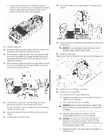
o If a processor and heatsink are installed in processor socket 2, then remove the server A system board assembly, route the cables between the heatsink and the system board, and install the system board assembly. 18. Connect the cable from the upper battery to the upper cache module. 11. Install the cable clips. 12. Route both cables around the edge of processor socket 2 and through the clip located near processor socket 2. 13. Route the battery cable attached to the lower battery through the clip near the DIMM slots, through the baffle and into the space between the mezzanine card mounting posts and the mezzanine connectors. 14. Route the battery cable connected to the upper battery through the clip near the DIMM slots, through the baffle and into the space near the signal connector. 19. Position any excess cable between the mezzanine card and the system board. CAUTION: To prevent battery cable and system board damage, always install the cable shield. 20. Install the cable shield. 15. Install the lower mezzanine card. The cables must lie flat between the mezzanine card and the system board. For more information, see the installation instructions that ship with the mezzanine cards. 16. Connect the cable from the lower battery to the lower cache module. 17. Install the upper mezzanine card. 21. Install the server A USB key, if removed. 22. Install the server B assembly: a. Extend the server B serial label pull tab. b. Engage the front edge of server B assembly with the front edge of server A assembly. c. Lower server B onto server A assembly. CAUTION: Route the cache module battery cables so that they do not become pinched when the server B assembly is installed. d. Align the signal and power connectors with the corresponding connectors on server A assembly. CAUTION: The jackscrews control the unseating and seating of critical system connectors. Failure to use the jackscrews to remove and install the server B assembly can cause the system boards to fail. e. Engage the threads on the right jackscrew and tighten six turns clockwise.
-
 1
1 -
 2
2 -
 3
3 -
 4
4
 |
 |
