HP BL680c ISS Technology Update, Volume 8, Number 4 - Page 4
CPU 0, CPU 1 - memory configuration
 |
UPC - 884420396314
View all HP BL680c manuals
Add to My Manuals
Save this manual to your list of manuals |
Page 4 highlights
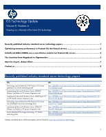
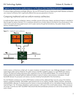
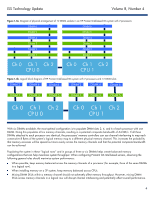
ISS Technology Update Volume 8, Number 4 Figure 1-3a. Diagram of physical arrangement of 12 DIMM sockets in an HP ProLiant Intel-based G6 system with 2 processors DIMM 6 DIMM 6 DIMM 5 DIMM 5 DIMM 4 DIMM 4 DIMM 3 DIMM 3 DIMM 2 DIMM 2 DIMM 1 DIMM 1 Ch 0 Ch 1 Ch 2 CP U 0 Ch 0 Ch 1 Ch 2 CP U 1 Figure 1-3b. Logical block diagram of HP ProLiant Intel-based G6 system with 2 processors and 12 DIMM slots DIMM 2 DIMM 4 DIMM 6 DIMM 2 DIMM 4 DIMM 6 DIMM 1 DIMM 3 DIMM 5 DIMM 1 DIMM 3 DIMM 5 Ch 0 Ch 1 Ch 2 CP U 0 Ch 0 Ch 1 Ch 2 CP U 1 With six DIMMs available, the most optimal configuration is to populate DIMM slots 2, 4, and 6 of each processor with one DIMM. Doing this populates all six memory channels, resulting in a potential composite bandwidth of 64 GB/s. If all three DIMMs attached to each processor are identical, the processors' memory controllers can use channel interleaving to map each consecutive 8 Bytes of the system's logical memory map to a different physical memory channel. This increases the probability that memory accesses will be spread out more evenly across the memory channels and that the potential composite bandwidth can be achieved. Populating the system in these ―logical rows‖ and in groups of three or six DIMMs helps create balanced memory configurations that can help maximize system throughput. When configuring ProLiant G6 Intel-based servers, observing the following general rules should maximize system performance: When possible, keep memory balanced across the memory channels of a processor (for example, three of the same DIMMs in a logical row). When installing memory on a 2P system, keep memory balanced across CPUs. Mixing DIMM SKUs within a memory channel should not adversely affect memory throughput. However, mixing DIMM SKUs across memory channels in a logical row will disrupt channel interleaving and potentially affect overall performance. 4
-
 1
1 -
 2
2 -
 3
3 -
 4
4 -
 5
5 -
 6
6 -
 7
7 -
 8
8
 |
 |
