| Section |
Page |
| Cisco Nexus 5000 Series Switch CLI Software Configuration Guide |
1 |
| Contents |
3 |
| Preface |
33 |
| Audience |
33 |
| Organization |
33 |
| Document Conventions |
34 |
| Related Documentation |
34 |
| Obtaining Documentation and Submitting a Service Request |
35 |
| Product Overview |
37 |
| New Technologies in the Cisco Nexus 5000 Series |
37 |
| Fibre Channel over Ethernet |
37 |
| I/O Consolidation |
38 |
| Virtual Interfaces |
39 |
| Cisco Nexus 5000 Series Switch Hardware |
39 |
| Chassis |
39 |
| Expansion Modules |
39 |
| Ethernet Interfaces |
39 |
| Fibre Channel Interfaces |
40 |
| Management Interfaces |
40 |
| Cisco Nexus 5000 Series Switch Software |
40 |
| Ethernet Switching |
40 |
| FCoE and Fibre Channel Switching |
41 |
| Licensing |
41 |
| QoS |
41 |
| Serviceability |
41 |
| Switched Port Analyzer |
41 |
| Ethanalyzer |
42 |
| Call Home |
42 |
| Online Diagnostics |
42 |
| Switch Management |
42 |
| Simple Network Management Protocol |
42 |
| Role-Based Access Control |
42 |
| Configuration Methods |
42 |
| Configuring with CLI, XML Management Interface, or SNMP |
43 |
| Configuring with Cisco MDS Fabric Manager |
43 |
| Network Security Features |
43 |
| Virtual Device Contexts |
43 |
| Typical Deployment Topologies |
43 |
| Ethernet TOR Switch Topology |
44 |
| IOC Topology |
45 |
| Supported Standards |
46 |
| Configuration Fundamentals |
47 |
| Using the Command-Line Interface |
49 |
| Accessing the Command Line Interface |
49 |
| Using the CLI |
50 |
| Using CLI Command Modes |
50 |
| Changing Command Modes |
51 |
| Listing the Commands Used with Each Command Mode |
51 |
| CLI Command Hierarchy |
51 |
| EXEC Mode Commands |
51 |
| Configuration Mode Commands |
53 |
| Using Commands |
54 |
| Listing Commands and Syntax |
54 |
| Entering Command Sequences |
55 |
| Undoing or Reverting to Default Values or Conditions |
55 |
| Using Keyboard Shortcuts |
55 |
| Using CLI Variables |
57 |
| User-Defined Persistent CLI Variables |
57 |
| Using Command Aliases |
58 |
| Defining Command Aliases |
58 |
| Command Scripts |
59 |
| Executing Commands Specified in a Script |
59 |
| Using CLI Variables in Scripts |
60 |
| Setting the Delay Time |
61 |
| Configuring the Switch |
63 |
| Image Files on the Switch |
63 |
| Starting the Switch |
64 |
| Boot Sequence |
64 |
| Console Settings |
65 |
| Upgrading the Switch |
66 |
| Upgrade Procedure Summary |
66 |
| Detailed Upgrade Procedure |
66 |
| Downgrading from a Higher Release |
68 |
| Initial Configuration |
69 |
| Configuration Prerequisites |
69 |
| Initial Setup |
70 |
| Preparing to Configure the Switch |
70 |
| Default Login |
71 |
| Configuring the Switch |
71 |
| Changing the Initial Configuration |
74 |
| Accessing the Switch |
74 |
| Additional Switch Configuration |
75 |
| Assigning a Switch Name |
75 |
| Configuring Date, Time, and Time Zone |
75 |
| Adjusting for Daylight Saving Time or Summer Time |
76 |
| NTP Configuration |
77 |
| About NTP |
77 |
| NTP Configuration Guidelines |
78 |
| Configuring NTP |
79 |
| NTP CFS Distribution |
79 |
| Enabling NTP Distribution |
80 |
| Committing NTP Configuration Changes |
80 |
| Discarding NTP Configuration Changes |
80 |
| Releasing Fabric Session Lock |
81 |
| Database Merge Guidelines |
81 |
| NTP Session Status Verification |
81 |
| Management Interface Configuration |
81 |
| About the mgmt0 Interface |
82 |
| Configuring the Management Interface |
82 |
| Displaying Management Interface Configuration |
82 |
| Shutting Down the Management Interface |
83 |
| Managing the Switch Configuration |
83 |
| Displaying the Switch Configuration |
83 |
| Saving a Configuration |
84 |
| Clearing a Configuration |
84 |
| Using Switch File Systems |
84 |
| Setting the Current Directory |
84 |
| Displaying the Current Directory |
85 |
| Listing the Files in a Directory |
85 |
| Creating a Directory |
85 |
| Deleting an Existing Directory |
85 |
| Moving Files |
86 |
| Copying Files |
86 |
| Deleting Files |
86 |
| Displaying File Contents |
87 |
| Displaying File Checksums |
87 |
| Saving Command Output to a File |
87 |
| Compressing and Uncompressing Files |
87 |
| Managing Licenses |
89 |
| Licensing Terminology |
89 |
| Licensing Model |
90 |
| License Installation |
91 |
| Obtaining a Factory-Installed License |
91 |
| Performing a Manual Installation |
92 |
| Obtaining the License Key File |
92 |
| Installing the License Key File |
92 |
| Backing Up License Files |
94 |
| Identifying License Features in Use |
94 |
| Uninstalling Licenses |
94 |
| Updating Licenses |
96 |
| Grace Period Alerts |
96 |
| License Transfers Between Switches |
97 |
| Verifying the License Configuration |
98 |
| LAN Switching |
99 |
| Configuring Ethernet Interfaces |
101 |
| Information About Ethernet Interfaces |
101 |
| About the Interface Command |
101 |
| About the Unidirectional Link Detection Parameter |
102 |
| UDLD Overview |
102 |
| Default UDLD Configuration |
103 |
| UDLD Aggressive and Nonaggressive Modes |
103 |
| About Interface Speed |
104 |
| About the Cisco Discovery Protocol |
104 |
| Default CDP Configuration |
104 |
| About the Debounce Timer Parameters |
104 |
| About MTU Configuration |
105 |
| Configuring Ethernet Interfaces |
105 |
| Configuring the UDLD Mode |
105 |
| Configuring Interface Speed |
106 |
| Configuring the Cisco Discovery Protocol |
107 |
| Configuring the CDP Characteristics |
107 |
| Enabling or Disabling CDP |
108 |
| Configuring the Debounce Timer |
108 |
| Configuring the Description Parameter |
109 |
| Disabling and Restarting Ethernet Interfaces |
109 |
| Displaying Interface Information |
110 |
| Default Physical Ethernet Settings |
112 |
| Configuring VLANs |
115 |
| Information About VLANs |
115 |
| Understanding VLANs |
115 |
| Understanding VLAN Ranges |
116 |
| Creating, Deleting, and Modifying VLANs |
117 |
| Configuring a VLAN |
118 |
| Creating and Deleting a VLAN |
118 |
| Entering the VLAN Submode and Configuring the VLAN |
119 |
| Adding Ports to a VLAN |
120 |
| Verifying VLAN Configuration |
120 |
| Configuring Private VLANs |
123 |
| About Private VLANs |
123 |
| Primary and Secondary VLANs in Private VLANs |
124 |
| Understanding Private VLAN Ports |
125 |
| Understanding Primary, Isolated, and Community Private VLANs |
125 |
| Associating Primary and Secondary VLANs |
126 |
| Understanding Broadcast Traffic in Private VLANs |
127 |
| Understanding Private VLAN Port Isolation |
127 |
| Configuring a Private VLAN |
127 |
| Configuration Guidelines for Private VLANs |
128 |
| Enabling Private VLANs |
128 |
| Configuring a VLAN as a Private VLAN |
129 |
| Associating Secondary VLANs with a Primary Private VLAN |
129 |
| Configuring an Interface as a Private VLAN Host Port |
130 |
| Configuring an Interface as a Private VLAN Promiscuous Port |
131 |
| Verifying Private VLAN Configuration |
132 |
| Configuring Rapid PVST+ |
135 |
| Information About Rapid PVST+ |
135 |
| Understanding STP |
136 |
| Overview |
136 |
| Understanding How a Topology is Created |
136 |
| Understanding the Bridge ID |
137 |
| Bridge Priority Value |
137 |
| Extended System ID |
137 |
| STP MAC Address Allocation |
138 |
| Understanding BPDUs |
138 |
| Election of the Root Bridge |
139 |
| Creating the Spanning Tree Topology |
139 |
| Understanding Rapid PVST+ |
140 |
| Overview |
140 |
| Rapid PVST+ BPDUs |
142 |
| Proposal and Agreement Handshake |
142 |
| Protocol Timers |
143 |
| Port Roles |
144 |
| Port States |
145 |
| Rapid PVST+ Port State Overview |
145 |
| Blocking State |
146 |
| Learning State |
146 |
| Forwarding State |
146 |
| Disabled State |
147 |
| Summary of Port States |
147 |
| Synchronization of Port Roles |
147 |
| Processing Superior BPDU Information |
148 |
| Processing Inferior BPDU Information |
148 |
| Detecting Unidirectional Link Failure |
148 |
| Port Cost |
149 |
| Port Priority |
150 |
| Rapid PVST+ and IEEE 802.1Q Trunks |
150 |
| Rapid PVST+ Interoperation with Legacy 802.1D STP |
150 |
| Rapid PVST+ Interoperation with 802.1s MST |
151 |
| Configuring Rapid PVST+ |
151 |
| Enabling Rapid PVST+ |
151 |
| Enabling Rapid PVST+ per VLAN |
152 |
| Configuring the Root Bridge ID |
153 |
| Configuring a Secondary Root Bridge |
154 |
| Configuring the Rapid PVST+ Port Priority |
155 |
| Configuring the Rapid PVST+ Pathcost Method and Port Cost |
155 |
| Configuring the Rapid PVST+ Bridge Priority of a VLAN |
156 |
| Configuring the Rapid PVST+ Hello Time for a VLAN |
157 |
| Configuring the Rapid PVST+ Forward Delay Time for a VLAN |
157 |
| Configuring the Rapid PVST+ Maximum Age Time for a VLAN |
157 |
| Specifying the Link Type |
158 |
| Restarting the Protocol |
159 |
| Verifying Rapid PVST+ Configurations |
159 |
| Configuring MST |
161 |
| Information About MST |
161 |
| MST Overview |
162 |
| MST Regions |
162 |
| MST BPDUs |
163 |
| MST Configuration Information |
163 |
| IST, CIST, and CST |
164 |
| IST, CIST, and CST Overview |
164 |
| Spanning Tree Operation Within an MST Region |
165 |
| Spanning Tree Operations Between MST Regions |
165 |
| MST Terminology |
166 |
| Hop Count |
167 |
| Boundary Ports |
167 |
| Detecting Unidirectional Link Failure |
168 |
| Port Cost and Port Priority |
168 |
| Interoperability with IEEE 802.1D |
169 |
| Interoperability with Rapid PVST+: Understanding PVST Simulation |
169 |
| Configuring MST |
169 |
| MST Configuration Guidelines |
170 |
| Enabling MST |
170 |
| Entering MST Configuration Mode |
171 |
| Specifying the MST Name |
172 |
| Specifying the MST Configuration Revision Number |
173 |
| Specifying the Configuration on an MST Region |
173 |
| Mapping and Unmapping VLANs to MST Instances |
175 |
| Mapping Secondary VLANs to Same MSTI as Primary VLANs for Private VLANs |
176 |
| Configuring the Root Bridge |
176 |
| Configuring a Secondary Root Bridge |
177 |
| Configuring the Port Priority |
178 |
| Configuring the Port Cost |
179 |
| Configuring the Switch Priority |
180 |
| Configuring the Hello Time |
181 |
| Configuring the Forwarding-Delay Time |
182 |
| Configuring the Maximum-Aging Time |
182 |
| Configuring the Maximum-Hop Count |
182 |
| Configuring PVST Simulation Globally |
183 |
| Configuring PVST Simulation Per Port |
183 |
| Specifying the Link Type |
184 |
| Restarting the Protocol |
185 |
| Verifying MST Configurations |
185 |
| Configuring STP Extensions |
187 |
| Information About STP Extensions |
187 |
| Understanding STP Port Types |
188 |
| Spanning Tree Edge Ports |
188 |
| Spanning Tree Network Ports |
188 |
| Spanning Tree Normal Ports |
188 |
| Understanding Bridge Assurance |
188 |
| Understanding BPDU Guard |
189 |
| Understanding BPDU Filtering |
189 |
| Understanding Loop Guard |
190 |
| Understanding Root Guard |
191 |
| Configuring STP Extensions |
191 |
| STP Extensions Configuration Guidelines |
191 |
| Configuring Spanning Tree Port Types Globally |
192 |
| Configuring Spanning Tree Edge Ports on Specified Interfaces |
193 |
| Configuring Spanning Tree Network Ports on Specified Interfaces |
193 |
| Enabling BPDU Guard Globally |
194 |
| Enabling BPDU Guard on Specified Interfaces |
195 |
| Enabling BPDU Filtering Globally |
196 |
| Enabling BPDU Filtering on Specified Interfaces |
196 |
| Enabling Loop Guard Globally |
198 |
| Enabling Loop Guard or Root Guard on Specified Interfaces |
198 |
| Verifying STP Extension Configuration |
199 |
| Configuring Port Channels |
201 |
| Information About Port Channels |
201 |
| Understanding Port Channels |
201 |
| Compatibility Requirements |
202 |
| Load Balancing Using Port Channels |
203 |
| Understanding LACP |
204 |
| LACP Overview |
205 |
| LACP ID Parameters |
205 |
| Port-Channel Modes |
206 |
| LACP Marker Responders |
207 |
| LACP-Enabled and Static Port Channels Differences |
207 |
| Configuring Port Channels |
207 |
| Creating a Port Channel |
207 |
| Adding a Port to a Port Channel |
208 |
| Configuring Load Balancing Using Port Channels |
209 |
| Enabling LACP |
210 |
| Configuring Port-Channel Port Modes |
210 |
| Configuring the LACP System Priority and System ID |
211 |
| Configuring the LACP Port Priority |
211 |
| Verifying Port-Channel Configuration |
212 |
| Configuring Access and Trunk Interfaces |
213 |
| Information About Access and Trunk Interfaces |
213 |
| Understanding Access and Trunk Interfaces |
213 |
| Understanding IEEE 802.1Q Encapsulation |
214 |
| Understanding Access VLANs |
215 |
| Understanding the Native VLAN ID for Trunk Ports |
215 |
| Understanding Allowed VLANs |
216 |
| Configuring Access and Trunk Interfaces |
216 |
| Configuring a LAN Interface as an Ethernet Access Port |
216 |
| Configuring Access Host Ports |
217 |
| Configuring Trunk Ports |
218 |
| Configuring the Native VLAN for 802.1Q Trunking Ports |
218 |
| Configuring the Allowed VLANs for Trunking Ports |
219 |
| Verifying Interface Configuration |
220 |
| Configuring the MAC Address Table |
221 |
| Information About MAC Addresses |
221 |
| Configuring MAC Addresses |
221 |
| Configuring a Static MAC Address |
222 |
| Configuring the Aging Time for the MAC Table |
222 |
| Clearing Dynamic Addresses from the MAC Table |
223 |
| Verifying the MAC Address Configuration |
223 |
| Configuring IGMP Snooping |
225 |
| Information About IGMP Snooping |
225 |
| IGMPv1 and IGMPv2 |
226 |
| IGMPv3 |
227 |
| IGMP Snooping Querier |
227 |
| IGMP Forwarding |
227 |
| Configuring IGMP Snooping Parameters |
228 |
| Verifying IGMP Snooping Configuration |
230 |
| Configuring Traffic Storm Control |
233 |
| Information About Traffic Storm Control |
233 |
| Guidelines and Limitations |
234 |
| Configuring Traffic Storm Control |
235 |
| Verifying Traffic Storm Control Configuration |
235 |
| Displaying Traffic Storm Control Counters |
235 |
| Traffic Storm Control Example Configuration |
236 |
| Default Settings |
236 |
| Switch Security Features |
237 |
| Configuring AAA |
239 |
| Information About AAA |
239 |
| AAA Security Services |
239 |
| Benefits of Using AAA |
240 |
| Remote AAA Services |
240 |
| AAA Server Groups |
241 |
| AAA Service Configuration Options |
241 |
| Authentication and Authorization Process for User Login |
242 |
| Prerequisites for Remote AAA |
243 |
| AAA Guidelines and Limitations |
244 |
| Configuring AAA |
244 |
| Configuring Console Login Authentication Methods |
244 |
| Configuring Default Login Authentication Methods |
246 |
| Enabling Login Authentication Failure Messages |
246 |
| Enabling MSCHAP Authentication |
247 |
| Configuring AAA Accounting Default Methods |
248 |
| Using AAA Server VSAs with Nexus 5000 Series Switches |
249 |
| About VSAs |
249 |
| VSA Format |
249 |
| Specifying Cisco Nexus 5000 Series Switch User Roles and SMNPv3 Parameters on AAA Servers |
249 |
| Displaying and Clearing the Local AAA Accounting Log |
250 |
| Verifying AAA Configuration |
250 |
| Example AAA Configuration |
250 |
| Default Settings |
251 |
| Configuring RADIUS |
253 |
| Information About RADIUS |
253 |
| RADIUS Network Environments |
253 |
| RADIUS Operation |
254 |
| RADIUS Server Monitoring |
255 |
| Vendor-Specific Attributes |
255 |
| Prerequisites for RADIUS |
256 |
| Guidelines and Limitations |
256 |
| Configuring RADIUS Servers |
256 |
| Configuring RADIUS Server Hosts |
257 |
| Configuring Global Preshared Keys |
258 |
| Configuring RADIUS Server Preshared Keys |
258 |
| Configuring RADIUS Server Groups |
259 |
| Allowing Users to Specify a RADIUS Server at Login |
260 |
| Configuring the Global RADIUS Transmission Retry Count and Timeout Interval |
261 |
| Configuring the RADIUS Transmission Retry Count and Timeout Interval for a Server |
261 |
| Configuring Accounting and Authentication Attributes for RADIUS Servers |
262 |
| Configuring Periodic RADIUS Server Monitoring |
263 |
| Configuring the Dead-Time Interval |
264 |
| Manually Monitoring RADIUS Servers or Groups |
265 |
| Verifying RADIUS Configuration |
265 |
| Displaying RADIUS Server Statistics |
265 |
| Example RADIUS Configuration |
266 |
| Default Settings |
266 |
| Configuring TACACS+ |
267 |
| Information About TACACS+ |
267 |
| TACACS+ Advantages |
268 |
| User Login with TACACS+ |
268 |
| Default TACACS+ Server Encryption Type and Preshared Key |
269 |
| TACACS+ Server Monitoring |
269 |
| Prerequisites for TACACS+ |
270 |
| Guidelines and Limitations |
270 |
| Configuring TACACS+ |
270 |
| TACACS+ Server Configuration Process |
270 |
| Enabling TACACS+ |
271 |
| Configuring TACACS+ Server Hosts |
271 |
| Configuring Global Preshared Keys |
272 |
| Configuring TACACS+ Server Preshared Keys |
273 |
| Configuring TACACS+ Server Groups |
273 |
| Specifying a TACACS+ Server at Login |
274 |
| Configuring the Global TACACS+ Timeout Interval |
275 |
| Configuring the Timeout Interval for a Server |
275 |
| Configuring TCP Ports |
276 |
| Configuring Periodic TACACS+ Server Monitoring |
277 |
| Configuring the Dead-Time Interval |
278 |
| Manually Monitoring TACACS+ Servers or Groups |
278 |
| Disabling TACACS+ |
278 |
| Displaying TACACS+ Statistics |
279 |
| Verifying TACACS+ Configuration |
279 |
| Example TACACS+ Configuration |
279 |
| Default Settings |
280 |
| Configuring SSH and Telnet |
281 |
| Information About SSH and Telnet |
281 |
| SSH Server |
281 |
| SSH Client |
282 |
| SSH Server Keys |
282 |
| Telnet Server |
282 |
| Prerequisites for SSH |
282 |
| Guidelines and Limitations |
283 |
| Configuring SSH |
283 |
| Generating SSH Server Keys |
283 |
| Specifying the SSH Public Keys for User Accounts |
284 |
| Specifying the SSH Public Keys in Open SSH Format |
284 |
| Specifying the SSH Public Keys in IETF SECSH Format |
284 |
| Specifying the SSH Public Keys in PEM-Formatted Public Key Certificate Form |
285 |
| Starting SSH Sessions to Remote Devices |
286 |
| Clearing SSH Hosts |
286 |
| Disabling the SSH Server |
286 |
| Deleting SSH Server Keys |
286 |
| Clearing SSH Sessions |
287 |
| Configuring Telnet |
287 |
| Enabling the Telnet Server |
287 |
| Starting Telnet Sessions to Remote Devices |
288 |
| Clearing Telnet Sessions |
288 |
| Verifying the SSH and Telnet Configuration |
289 |
| SSH Example Configuration |
289 |
| Default Settings |
290 |
| Configuring ACLs |
291 |
| Information About ACLs |
291 |
| IP ACL Types and Applications |
291 |
| Application Order |
292 |
| Rules |
292 |
| Source and Destination |
292 |
| Protocols |
292 |
| Implicit Rules |
293 |
| Additional Filtering Options |
293 |
| Sequence Numbers |
293 |
| Logical Operators and Logical Operation Units |
294 |
| Configuring IP ACLs |
294 |
| Creating an IP ACL |
295 |
| Changing an IP ACL |
295 |
| Removing an IP ACL |
296 |
| Changing Sequence Numbers in an IP ACL |
297 |
| Applying an IP ACL as a Port ACL |
297 |
| Applying an IP ACL as a VACL |
298 |
| Verifying IP ACL Configurations |
298 |
| Displaying and Clearing IP ACL Statistics |
299 |
| Configuring MAC ACLs |
299 |
| Creating a MAC ACL |
300 |
| Changing a MAC ACL |
300 |
| Removing a MAC ACL |
301 |
| Changing Sequence Numbers in a MAC ACL |
302 |
| Applying a MAC ACL as a Port ACL |
302 |
| Applying a MAC ACL as a VACL |
303 |
| Verifying MAC ACL Configurations |
303 |
| Displaying and Clearing MAC ACL Statistics |
303 |
| Information About VLAN ACLs |
304 |
| VACLs and Access Maps |
304 |
| VACLs and Actions |
304 |
| Statistics |
305 |
| Configuring VACLs |
305 |
| Creating or Changing a VACL |
305 |
| Removing a VACL |
306 |
| Applying a VACL to a VLAN |
306 |
| Verifying VACL Configuration |
307 |
| Displaying and Clearing VACL Statistics |
307 |
| Default Settings |
308 |
| System Management |
309 |
| Using Cisco Fabric Services |
311 |
| Information About CFS |
311 |
| CFS Distribution |
312 |
| CFS Distribution Modes |
312 |
| Uncoordinated Distribution |
313 |
| Coordinated Distribution |
313 |
| Unrestricted Uncoordinated Distributions |
313 |
| Enabling/Disabling CFS Distribution on a Switch |
313 |
| Verifying CFS Distribution Status |
314 |
| CFS Distribution over IP |
314 |
| CFS Distribution over Fibre Channel |
315 |
| CFS Distribution Scopes |
315 |
| CFS Merge Support |
316 |
| CFS Support for Applications |
316 |
| CFS Application Requirements |
316 |
| Enabling CFS for an Application |
317 |
| Verifying Application Registration Status |
317 |
| Locking the Network |
318 |
| Verifying CFS Lock Status |
318 |
| Committing Changes |
318 |
| Discarding Changes |
319 |
| Saving the Configuration |
319 |
| Clearing a Locked Session |
319 |
| CFS Regions |
319 |
| About CFS Regions |
320 |
| Example Scenario |
320 |
| Managing CFS Regions |
320 |
| Creating CFS Regions |
321 |
| Assigning Applications to CFS Regions |
321 |
| Moving an Application to a Different CFS Region |
321 |
| Removing an Application from a Region |
321 |
| Deleting CFS Regions |
322 |
| Configuring CFS over IP |
322 |
| Enabling CFS over IP |
322 |
| Verifying the CFS Over IP Configuration |
323 |
| Configuring IP Multicast Address for CFS over IP |
323 |
| Verifying IP Multicast Address Configuration for CFS over IP |
324 |
| Displaying CFS Distribution Information |
324 |
| Default Settings |
326 |
| Configuring User Accounts and RBAC |
327 |
| Information About User Accounts and RBAC |
327 |
| About User Accounts |
327 |
| Characteristics of Strong Passwords |
328 |
| About User Roles |
328 |
| About Rules |
329 |
| About User Role Policies |
329 |
| Guidelines and Limitations |
330 |
| Configuring User Accounts |
330 |
| Configuring RBAC |
331 |
| Creating User Roles and Rules |
331 |
| Creating Feature Groups |
333 |
| Changing User Role Interface Policies |
333 |
| Changing User Role VLAN Policies |
334 |
| Changing User Role VSAN Policies |
334 |
| Verifying User Accounts and RBAC Configuration |
335 |
| Example User Accounts and RBAC Configuration |
335 |
| Default Settings |
336 |
| Configuring Session Manager |
337 |
| Information About Session Manager |
337 |
| Configuration Guidelines and Limitations |
337 |
| Configuring Session Manager |
338 |
| Creating a Session |
338 |
| Configuring ACLs in a Session |
338 |
| Verifying a Session |
339 |
| Committing a Session |
339 |
| Saving a Session |
339 |
| Discarding a Session |
339 |
| Session Manager Example Configuration |
339 |
| Verifying Session Manager Configuration |
340 |
| Configuring Online Diagnostics |
341 |
| Information About Online Diagnostics |
341 |
| Online Diagnostics Overview |
341 |
| Bootup Diagnostics |
341 |
| Health Monitoring Diagnostics |
342 |
| Expansion Module Diagnostics |
343 |
| Configuring Online Diagnostics |
344 |
| Verifying Online Diagnostics Configuration |
344 |
| Default Settings |
344 |
| Configuring System Message Logging |
347 |
| Information About System Message Logging |
347 |
| syslog Servers |
348 |
| Configuring System Message Logging |
348 |
| Configuring System Message Logging to Terminal Sessions |
348 |
| Configuring System Message Logging to a File |
349 |
| Configuring Module and Facility Messages Logged |
350 |
| Configuring syslog Servers |
351 |
| Configuring syslog Server Configuration Distribution |
353 |
| Displaying and Clearing Log Files |
354 |
| Verifying System Message Logging Configuration |
355 |
| System Message Logging Example Configuration |
355 |
| Default Settings |
356 |
| Configuring Smart Call Home |
357 |
| Information About Call Home |
357 |
| Call Home Overview |
357 |
| Destination Profiles |
358 |
| Call Home Alert Groups |
358 |
| Call Home Message Levels |
360 |
| Obtaining Smart Call Home |
361 |
| Prerequisites for Call Home |
361 |
| Configuration Guidelines and Limitations |
361 |
| Configuring Call Home |
362 |
| Guidelines for Configuring Call Home |
362 |
| Configuring Contact Information |
362 |
| Creating a Destination Profile |
364 |
| Modifying a Destination Profile |
364 |
| Associating an Alert Group with a Destination Profile |
365 |
| Adding show Commands to an Alert Group |
366 |
| Configuring E-Mail |
366 |
| Configuring Periodic Inventory Notification |
367 |
| Disabling Duplicate Message Throttle |
368 |
| Enabling or Disabling Call Home |
368 |
| Testing Call Home Communications |
369 |
| Verifying Call Home Configuration |
369 |
| Call Home Example Configuration |
370 |
| Default Settings |
370 |
| Additional References |
371 |
| Message Formats |
371 |
| Sample syslog Alert Notification in Full-Text Format |
374 |
| Sample syslog Alert Notification in XML Format |
375 |
| Configuring SNMP |
379 |
| Information About SNMP |
379 |
| SNMP Functional Overview |
379 |
| SNMP Notifications |
380 |
| SNMPv3 |
380 |
| Security Models and Levels for SNMPv1, v2, v3 |
380 |
| User-Based Security Model |
381 |
| CLI and SNMP User Synchronization |
382 |
| Group-Based SNMP Access |
382 |
| Configuration Guidelines and Limitations |
383 |
| Configuring SNMP |
383 |
| Configuring SNMP Users |
383 |
| Enforcing SNMP Message Encryption |
383 |
| Assigning SNMPv3 Users to Multiple Roles |
384 |
| Creating SNMP Communities |
384 |
| Configuring SNMP Notification Receivers |
384 |
| Configuring the Notification Target User |
385 |
| Enabling SNMP Notifications |
386 |
| Configuring linkUp/linkDown Notifications |
387 |
| Disabling Up/ Down Notifications on an Interface |
388 |
| Enabling One-Time Authentication for SNMP over TCP |
388 |
| Assigning SNMP Switch Contact and Location Information |
389 |
| Verifying SNMP Configuration |
389 |
| SNMP Example Configuration |
389 |
| Default Settings |
390 |
| Configuring RMON |
391 |
| Information About RMON |
391 |
| RMON Alarms |
391 |
| RMON Events |
392 |
| Configuration Guidelines and Limitations |
392 |
| Configuring RMON |
393 |
| Configuring RMON Alarms |
393 |
| Configuring RMON Events |
394 |
| Verifying RMON Configuration |
394 |
| RMON Example Configuration |
394 |
| Default Settings |
395 |
| Fibre Channel over Ethernet |
397 |
| Configuring FCoE |
399 |
| Information About FCoE |
399 |
| Licensing Requirements |
399 |
| Converged Network Adapters |
400 |
| DCBX Capabilities |
400 |
| FCoE |
400 |
| Priority Flow Control |
400 |
| Logical Link Up/Down |
401 |
| DCE Bridging Capability Exchange Protocol |
401 |
| DCBX Feature Negotiation |
401 |
| Ethernet Frame Formats |
402 |
| Configuring FCoE |
402 |
| Enabling FCoE |
403 |
| Enabling FCoE on Ethernet Interfaces |
403 |
| Configuring Priority Flow Control |
404 |
| Configuring IEEE 802.3x Link-Level Flow Control |
404 |
| Configuring LLDP |
404 |
| Configuring Global LLDP Commands |
405 |
| Configuring Interface LLDP Commands |
405 |
| Verifying FCoE Configuration |
406 |
| Configuring Virtual Interfaces |
407 |
| Information About Virtual Interfaces |
407 |
| Guidelines and Limitations |
407 |
| Configuring Virtual Interfaces |
408 |
| Creating a Virtual Fibre Channel Interface |
408 |
| Mapping VSANs to VLANs |
408 |
| Deleting a Virtual Fibre Channel Interface |
409 |
| Verifying Virtual Interface Information |
410 |
| Quality of Service |
413 |
| Configuring QoS |
415 |
| Information About QoS |
415 |
| MQC |
416 |
| System Classes |
416 |
| Default System Classes |
417 |
| Link-Level Flow Control |
417 |
| Priority Flow Control |
417 |
| MTU |
418 |
| Trust Boundaries |
418 |
| Ingress Policies |
419 |
| Egress Policies |
419 |
| QoS for Multicast Traffic |
419 |
| Policy for Fibre Channel Interfaces |
420 |
| QoS for Traffic Directed to the CPU |
420 |
| Configuration Guidelines and Limitations |
420 |
| Configuring PFC and LLC |
421 |
| Configuring Priority Flow Control |
421 |
| Configuring IEEE 802.3x Link-Level Flow Control |
422 |
| Configuring System Classes |
423 |
| Configuring Class Maps |
423 |
| Configuring Policy Maps |
424 |
| Creating the System Service Policy |
425 |
| System Class Example |
425 |
| Enabling Jumbo MTU |
426 |
| Verifying Jumbo MTU |
426 |
| Configuring QoS on Interfaces |
427 |
| Configuring Ingress Policies |
427 |
| Configuring Egress Policies |
428 |
| SAN Switching |
431 |
| Configuring Fibre Channel Interfaces |
433 |
| Information About Fibre Channel Interfaces |
433 |
| Licensing Requirements |
433 |
| Physical Fibre Channel Interfaces |
434 |
| Virtual Fibre Channel Interfaces |
434 |
| Interface Modes |
434 |
| E Port |
435 |
| F Port |
436 |
| NP Port |
436 |
| TE Port |
436 |
| SD Port |
436 |
| Auto Mode |
436 |
| Interface States |
437 |
| Administrative States |
437 |
| Operational States |
437 |
| Reason Codes |
437 |
| Buffer-to-Buffer Credits |
439 |
| Configuring Fibre Channel Interfaces |
440 |
| Configuring a Fibre Channel Interface |
440 |
| Setting the Interface Administrative State |
441 |
| Configuring Interface Modes |
441 |
| Configuring the Interface Description |
442 |
| Configuring Port Speeds |
442 |
| Autosensing |
443 |
| Configuring SD Port Frame Encapsulation |
443 |
| Configuring Receive Data Field Size |
443 |
| Understanding Bit Error Thresholds |
443 |
| Configuring Buffer-to-Buffer Credits |
444 |
| Configuring Global Attributes for Fibre Channel Interfaces |
445 |
| Configuring Switch Port Attribute Default Values |
445 |
| About N Port Identifier Virtualization |
446 |
| Enabling N Port Identifier Virtualization |
446 |
| Verifying Fibre Channel Interfaces |
447 |
| Verifying SFP Transmitter Types |
447 |
| Verifying Interface Information |
447 |
| Verifying BB_Credit Information |
449 |
| Default Settings |
449 |
| Configuring Domain Parameters |
451 |
| Information About Fibre Channel Domains |
451 |
| About Domain Restart |
453 |
| Restarting a Domain |
453 |
| About Domain Manager Fast Restart |
453 |
| Enabling Domain Manager Fast Restart |
454 |
| About Switch Priority |
454 |
| Configuring Switch Priority |
454 |
| About fcdomain Initiation |
455 |
| Disabling or Reenabling fcdomains |
455 |
| Configuring Fabric Names |
455 |
| About Incoming RCFs |
455 |
| Rejecting Incoming RCFs |
456 |
| About Autoreconfiguring Merged Fabrics |
456 |
| Enabling Autoreconfiguration |
456 |
| Domain IDs |
456 |
| About Domain IDs |
457 |
| Specifying Static or Preferred Domain IDs |
459 |
| About Allowed Domain ID Lists |
459 |
| Configuring Allowed Domain ID Lists |
460 |
| About CFS Distribution of Allowed Domain ID Lists |
460 |
| Enabling Distribution |
460 |
| Locking the Fabric |
461 |
| Committing Changes |
461 |
| Discarding Changes |
461 |
| Clearing a Fabric Lock |
462 |
| Displaying CFS Distribution Status |
462 |
| Displaying Pending Changes |
462 |
| Displaying Session Status |
463 |
| About Contiguous Domain ID Assignments |
463 |
| Enabling Contiguous Domain ID Assignments |
463 |
| FC IDs |
463 |
| About Persistent FC IDs |
464 |
| Enabling the Persistent FC ID Feature |
464 |
| Persistent FC ID Configuration Guidelines |
465 |
| Configuring Persistent FC IDs |
465 |
| About Unique Area FC IDs for HBAs |
466 |
| Configuring Unique Area FC IDs for an HBA |
466 |
| About Persistent FC ID Selective Purging |
467 |
| Purging Persistent FC IDs |
468 |
| Verifying fcdomain Information |
468 |
| Default Settings |
469 |
| Configuring N Port Virtualization |
471 |
| Information About NPV |
471 |
| NPV Overview |
471 |
| NPV Mode |
472 |
| Server Interfaces |
472 |
| NP Uplinks (External Interfaces) |
473 |
| FLOGI Operation |
473 |
| NPV Traffic Management |
474 |
| Automatic Uplink Selection |
474 |
| Traffic Maps |
474 |
| Disruptive Load Balancing |
474 |
| NPV Traffic Management Guidelines |
475 |
| Guidelines and Limitations |
475 |
| Configuring NPV |
476 |
| Enabling NPV |
476 |
| Configuring NPV Interfaces |
477 |
| Configuring NPV Traffic Management |
477 |
| Configuring NPV Traffic Maps |
477 |
| Enabling Disruptive Load Balancing |
478 |
| Verifying NPV |
478 |
| Verifying NPV Traffic Management |
479 |
| Configuring VSAN Trunking |
481 |
| Information About VSAN Trunking |
481 |
| VSAN Trunking Mismatches |
482 |
| VSAN Trunking Protocol |
482 |
| Configuring VSAN Trunking |
483 |
| Guidelines and Restrictions |
483 |
| Enabling or Disabling the VSAN Trunking Protocol |
483 |
| About Trunk Mode |
483 |
| Configuring Trunk Mode |
484 |
| About Trunk-Allowed VSAN Lists |
484 |
| Configuring an Allowed-Active List of VSANs |
486 |
| Displaying VSAN Trunking Information |
486 |
| Default Settings |
487 |
| Configuring SAN Port Channels |
489 |
| Information About SAN Port Channels |
489 |
| Understanding Port Channels and VSAN Trunking |
490 |
| Understanding Load Balancing |
490 |
| Configuring SAN Port Channels |
492 |
| SAN Port Channel Configuration Guidelines |
493 |
| Creating a SAN Port Channel |
494 |
| About SAN Port Channel Modes |
494 |
| About SAN Port Channel Deletion |
495 |
| Deleting SAN Port Channels |
496 |
| Interfaces in a SAN Port Channel |
496 |
| About Interface Addition to a SAN Port Channel |
497 |
| Compatibility Check |
497 |
| Suspended and Isolated States |
497 |
| Adding an Interface to a SAN Port Channel |
497 |
| Forcing an Interface Addition |
498 |
| About Interface Deletion from a SAN Port Channel |
498 |
| Deleting an Interface from a SAN Port Channel |
499 |
| Port Channel Protocol |
499 |
| About Channel Group Creation |
500 |
| Autocreation Guidelines |
501 |
| Enabling and Configuring Autocreation |
502 |
| About Manually Configured Channel Groups |
502 |
| Converting to Manually Configured Channel Groups |
502 |
| Verifying SAN Port Channel Configuration |
503 |
| Default Settings |
504 |
| Configuring and Managing VSANs |
505 |
| Information About VSANs |
505 |
| VSAN Topologies |
505 |
| VSAN Advantages |
507 |
| VSANs Versus Zones |
508 |
| Configuring VSANs |
509 |
| About VSAN Creation |
510 |
| Creating VSANs Statically |
510 |
| About Port VSAN Membership |
511 |
| Assigning Static Port VSAN Membership |
511 |
| Displaying VSAN Static Membership |
511 |
| About the Default VSAN |
512 |
| About the Isolated VSAN |
512 |
| Displaying Isolated VSAN Membership |
512 |
| Operational State of a VSAN |
513 |
| About Static VSAN Deletion |
513 |
| Deleting Static VSANs |
514 |
| About Load Balancing |
514 |
| Configuring Load Balancing |
514 |
| About Interop Mode |
515 |
| Displaying Static VSAN Configuration |
515 |
| Default Settings |
515 |
| Configuring and Managing Zones |
517 |
| Information About Zoning |
517 |
| Zoning Features |
518 |
| Zoning Example |
519 |
| Zone Implementation |
520 |
| Active and Full Zone Set Configuration Guidelines |
520 |
| Configuring Zones |
523 |
| Zone Sets |
524 |
| Activating a Zone Set |
525 |
| About the Default Zone |
526 |
| Configuring the Default Zone Access Permission |
526 |
| About FC Alias Creation |
526 |
| Creating FC Aliases |
527 |
| Creating Zone Sets and Adding Member Zones |
528 |
| Zone Enforcement |
529 |
| Zone Set Distribution |
529 |
| Enabling Full Zone Set Distribution |
530 |
| Enabling a One-Time Distribution |
530 |
| About Recovering from Link Isolation |
530 |
| Importing and Exporting Zone Sets |
531 |
| Zone Set Duplication |
532 |
| Copying Zone Sets |
532 |
| Renaming Zones, Zone Sets, and Aliases |
532 |
| Cloning Zones, Zone Sets, FC Aliases, and Zone Attribute Groups |
533 |
| Clearing the Zone Server Database |
533 |
| Verifying Zone Information |
534 |
| Enhanced Zoning |
534 |
| About Enhanced Zoning |
535 |
| Changing from Basic Zoning to Enhanced Zoning |
536 |
| Changing from Enhanced Zoning to Basic Zoning |
536 |
| Enabling Enhanced Zoning |
536 |
| Modifying the Zone Database |
537 |
| Releasing Zone Database Locks |
537 |
| Merging the Database |
538 |
| Configuring Zone Merge Control Policies |
539 |
| Default Zone Policies |
539 |
| Configuring System Default Zoning Settings |
539 |
| Verifying Enhanced Zone Information |
540 |
| Compacting the Zone Database |
540 |
| Zone and Zone Set Analysis |
540 |
| Default Settings |
541 |
| Distributing Device Alias Services |
543 |
| Information About Device Aliases |
543 |
| Device Alias Features |
543 |
| Device Alias Requirements |
544 |
| Zone Aliases Versus Device Aliases |
544 |
| Device Alias Databases |
544 |
| Creating Device Aliases |
545 |
| Device Alias Modes |
546 |
| Changing Device Alias Mode Guidelines |
546 |
| Configuring Device Alias Modes |
547 |
| About Device Alias Distribution |
547 |
| Locking the Fabric |
547 |
| Committing Changes |
548 |
| Discarding Changes |
548 |
| Fabric Lock Override |
549 |
| Disabling and Enabling Device Alias Distribution |
549 |
| About Legacy Zone Alias Configuration |
550 |
| Importing a Zone Alias |
550 |
| Database Merge Guidelines |
550 |
| Verifying Device Alias Configuration |
551 |
| Default Settings |
552 |
| Configuring Fibre Channel Routing Services and Protocols |
553 |
| Information About FSPF |
553 |
| FSPF Examples |
554 |
| Fault Tolerant Fabric Example |
554 |
| Redundant Link Example |
554 |
| FSPF Global Configuration |
555 |
| About SPF Computational Hold Times |
555 |
| About Link State Records |
556 |
| Configuring FSPF on a VSAN |
556 |
| Resetting FSPF to the Default Configuration |
557 |
| Enabling or Disabling FSPF |
557 |
| Clearing FSPF Counters for the VSAN |
557 |
| FSPF Interface Configuration |
557 |
| About FSPF Link Cost |
558 |
| Configuring FSPF Link Cost |
558 |
| About Hello Time Intervals |
558 |
| Configuring Hello Time Intervals |
558 |
| About Dead Time Intervals |
559 |
| Configuring Dead Time Intervals |
559 |
| About Retransmitting Intervals |
559 |
| Configuring Retransmitting Intervals |
560 |
| About Disabling FSPF for Specific Interfaces |
560 |
| Disabling FSPF for Specific Interfaces |
560 |
| Clearing FSPF Counters for an Interface |
561 |
| FSPF Routes |
561 |
| About Fibre Channel Routes |
561 |
| Configuring Fibre Channel Routes |
562 |
| In-Order Delivery |
562 |
| About Reordering Network Frames |
563 |
| About Reordering SAN Port Channel Frames |
563 |
| About Enabling In-Order Delivery |
564 |
| Enabling In-Order Delivery Globally |
564 |
| Enabling In-Order Delivery for a VSAN |
565 |
| Displaying the In-Order Delivery Status |
565 |
| Configuring the Drop Latency Time |
565 |
| Displaying Latency Information |
566 |
| Flow Statistics Configuration |
566 |
| About Flow Statistics |
567 |
| Counting Aggregated Flow Statistics |
567 |
| Counting Individual Flow Statistics |
567 |
| Clearing FIB Statistics |
567 |
| Displaying Flow Statistics |
568 |
| Default Settings |
568 |
| Managing FLOGI, Name Server, FDMI, and RSCN Databases |
571 |
| Information About Fabric Login |
571 |
| Name Server Proxy |
572 |
| About Registering Name Server Proxies |
572 |
| Registering Name Server Proxies |
572 |
| About Rejecting Duplicate pWWNs |
572 |
| Rejecting Duplicate pWWNs |
573 |
| About Name Server Database Entries |
573 |
| Displaying Name Server Database Entries |
573 |
| FDMI |
574 |
| Displaying FDMI |
574 |
| RSCN |
574 |
| About RSCN Information |
575 |
| Displaying RSCN Information |
575 |
| About the multi-pid Option |
575 |
| Configuring the multi-pid Option |
576 |
| Suppressing Domain Format SW-RSCNs |
576 |
| Clearing RSCN Statistics |
576 |
| Configuring the RSCN Timer |
577 |
| Verifying the RSCN Timer Configuration |
577 |
| RSCN Timer Configuration Distribution |
578 |
| Enabling RSCN Timer Configuration Distribution |
578 |
| Locking the Fabric |
578 |
| Committing the RSCN Timer Configuration Changes |
579 |
| Discarding the RSCN Timer Configuration Changes |
579 |
| Clearing a Locked Session |
579 |
| Displaying RSCN Configuration Distribution Information |
579 |
| Default Settings |
580 |
| Discovering SCSI Targets |
581 |
| Information About SCSI LUN Discovery |
581 |
| About Starting SCSI LUN Discovery |
581 |
| Starting SCSI LUN Discovery |
582 |
| About Initiating Customized Discovery |
582 |
| Initiating Customized Discovery |
582 |
| Displaying SCSI LUN Information |
583 |
| Advanced Fibre Channel Features and Concepts |
585 |
| Fibre Channel Timeout Values |
585 |
| Timer Configuration Across All VSANs |
586 |
| Timer Configuration Per-VSAN |
586 |
| About fctimer Distribution |
587 |
| Enabling or Disabling fctimer Distribution |
587 |
| Committing fctimer Changes |
587 |
| Discarding fctimer Changes |
588 |
| Fabric Lock Override |
588 |
| Database Merge Guidelines |
588 |
| Verifying Configured fctimer Values |
589 |
| World Wide Names |
589 |
| Verifying WWN Information |
590 |
| Link Initialization WWN Usage |
590 |
| Configuring a Secondary MAC Address |
590 |
| FC ID Allocation for HBAs |
591 |
| Default Company ID List |
591 |
| Verifying the Company ID Configuration |
592 |
| Switch Interoperability |
593 |
| About Interop Mode |
593 |
| Configuring Interop Mode 1 |
595 |
| Verifying Interoperating Status |
596 |
| Default Settings |
599 |
| Configuring FC-SP and DHCHAP |
601 |
| Information About Fabric Authentication |
601 |
| DHCHAP |
602 |
| DHCHAP Compatibility with Fibre Channel Features |
603 |
| About Enabling DHCHAP |
604 |
| Enabling DHCHAP |
604 |
| About DHCHAP Authentication Modes |
604 |
| Configuring the DHCHAP Mode |
605 |
| About the DHCHAP Hash Algorithm |
605 |
| Configuring the DHCHAP Hash Algorithm |
606 |
| About the DHCHAP Group Settings |
606 |
| Configuring the DHCHAP Group Settings |
606 |
| About the DHCHAP Password |
606 |
| Configuring DHCHAP Passwords for the Local Switch |
607 |
| About Password Configuration for Remote Devices |
607 |
| Configuring DHCHAP Passwords for Remote Devices |
608 |
| About the DHCHAP Timeout Value |
608 |
| Configuring the DHCHAP Timeout Value |
608 |
| Configuring DHCHAP AAA Authentication |
609 |
| Displaying Protocol Security Information |
609 |
| Sample Configuration |
609 |
| Default Settings |
611 |
| Configuring Port Security |
613 |
| Information About Port Security |
613 |
| Port Security Enforcement |
614 |
| About Auto-Learning |
614 |
| Port Security Activation |
615 |
| Configuring Port Security |
615 |
| Configuring Port Security with Auto-Learning and CFS Distribution |
615 |
| Configuring Port Security with Auto-Learning without CFS |
616 |
| Configuring Port Security with Manual Database Configuration |
617 |
| Enabling Port Security |
617 |
| Port Security Activation |
617 |
| Activating Port Security |
618 |
| Database Activation Rejection |
618 |
| Forcing Port Security Activation |
618 |
| Database Reactivation |
619 |
| Auto-Learning |
619 |
| About Enabling Auto-Learning |
620 |
| Enabling Auto-Learning |
620 |
| Disabling Auto-Learning |
620 |
| Auto-Learning Device Authorization |
620 |
| Authorization Scenario |
621 |
| Port Security Manual Configuration |
622 |
| WWN Identification Guidelines |
622 |
| Adding Authorized Port Pairs |
623 |
| Port Security Configuration Distribution |
624 |
| Enabling Distribution |
624 |
| Locking the Fabric |
625 |
| Committing the Changes |
625 |
| Discarding the Changes |
625 |
| Activation and Auto-Learning Configuration Distribution |
625 |
| Database Merge Guidelines |
626 |
| Database Interaction |
627 |
| Database Scenarios |
627 |
| Copying the Port Security Database |
629 |
| Deleting the Port Security Database |
630 |
| Clearing the Port Security Database |
630 |
| Displaying Port Security Configuration |
631 |
| Default Settings |
631 |
| Configuring Fabric Binding |
633 |
| Information About Fabric Binding |
633 |
| Licensing Requirements |
633 |
| Port Security Versus Fabric Binding |
634 |
| Fabric Binding Enforcement |
634 |
| Configuring Fabric Binding |
635 |
| Configuring Fabric Binding |
635 |
| Enabling Fabric Binding |
635 |
| About Switch WWN Lists |
636 |
| Configuring Switch WWN List |
636 |
| About Fabric Binding Activation and Deactivation |
636 |
| Activating Fabric Binding |
637 |
| Forcing Fabric Binding Activation |
637 |
| Copying Fabric Binding Configurations |
637 |
| Clearing the Fabric Binding Statistics |
638 |
| Deleting the Fabric Binding Database |
638 |
| Verifying Fabric Binding Information |
638 |
| Default Settings |
639 |
| Configuring Fabric Configuration Servers |
641 |
| Information About FCS |
641 |
| FCS Characteristics |
642 |
| FCS Name Specification |
642 |
| Displaying FCS Information |
643 |
| Default Settings |
644 |
| Configuring Port Tracking |
645 |
| Information About Port Tracking |
645 |
| Configuring Port Tracking |
646 |
| Enabling Port Tracking |
647 |
| About Configuring Linked Ports |
647 |
| Operationally Binding a Tracked Port |
647 |
| About Tracking Multiple Ports |
648 |
| Tracking Multiple Ports |
649 |
| About Monitoring Ports in a VSAN |
649 |
| Monitoring Ports in a VSAN |
649 |
| About Forceful Shutdown |
650 |
| Forcefully Shutting Down a Tracked Port |
650 |
| Displaying Port Tracking Information |
650 |
| Default Port Tracking Settings |
651 |
| Troubleshooting |
653 |
| Configuring SPAN |
655 |
| SPAN Sources |
655 |
| Characteristics of Source Ports |
655 |
| SPAN Destinations |
656 |
| Characteristics of Destination Ports |
656 |
| Configuring SPAN |
656 |
| Creating and Deleting a SPAN Session |
657 |
| Configuring the Destination Port |
657 |
| Configuring an Ethernet Destination Port |
658 |
| Configuring Fibre Channel Destination Port |
658 |
| Configuring Source Ports |
659 |
| Configuring Source Port Channels, VLANs, or VSANs |
659 |
| Configuring the Description of a SPAN Session |
660 |
| Suspending or Activating a SPAN Session |
661 |
| Displaying SPAN Information |
661 |
| Troubleshooting |
663 |
| Recovering a Lost Password |
663 |
| Using the CLI with Network-Admin Privileges |
663 |
| Power Cycling the Switch |
664 |
| Using Ethanalyzer |
665 |
| Troubleshooting Fibre Channel |
667 |
| fctrace |
667 |
| fcping |
669 |
| Verifying Switch Connectivity |
669 |
| show tech-support Command |
670 |
| show tech-support brief Command |
672 |
| show tech-support fc Command |
674 |
| show tech-support platform Command |
676 |
| Default Settings |
678 |
 1
1 467
467 468
468 469
469 470
470 471
471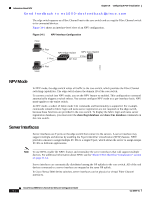 472
472 473
473 474
474 475
475 476
476 477
477

