HP Cisco MDS 9134 Cisco MDS 9500 Series Hardware Installation Guide (OL-17467- - Page 161
Clock B CLK B
 |
View all HP Cisco MDS 9134 manuals
Add to My Manuals
Save this manual to your list of manuals |
Page 161 highlights
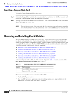
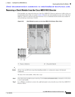
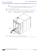
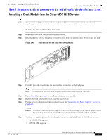
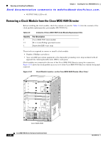
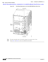
Chapter 2 Installing the Cisco MDS 9500 Series Removing and Installing Clock Modules Send documentation comments to [email protected]. 1 Clock A (CLK A) 2 Clock B (CLK B) Caution Always wear an ESD wrist strap when handling modules or coming into contact with internal components. To remove the clock module, follow these steps: Step 1 Remove power from both power supplies as follows: • If the power supply is AC, press the power switch to off (0) and remove the power cable. • If the power supply is DC, follow the instructions in the "Providing Power to a DC Power Supply in the Cisco MDS 9509 Director" section on page 2-33. Caution Before working on a system that has an on/off switch, turn off the power and unplug the power cord. Step 2 Use a Phillips screwdriver to remove the 18 back panel screws from the rear of the Cisco MDS 9509 Director chassis. Note Note the position of the clock module before you remove it from the director chassis because you must install the new clock module in the same position. Step 3 Remove the four screws that secure the clock module to the backplane. (See Figure 2-44.) OL-17467-02 Cisco MDS 9500 Series Hardware Installation Guide 2-81
-
 1
1 -
2
-
3
-
4
-
5
-
6
-
7
-
8
-
9
-
10
-
11
-
12
-
13
-
14
-
15
-
16
-
17
-
18
-
19
-
20
-
21
-
22
-
23
-
24
-
25
-
26
-
27
-
28
-
29
-
30
-
31
-
32
-
33
-
34
-
35
-
36
-
37
-
38
-
39
-
40
-
41
-
42
-
43
-
44
-
45
-
46
-
47
-
48
-
49
-
50
-
51
-
52
-
53
-
54
-
55
-
56
-
57
-
58
-
59
-
60
-
61
-
62
-
63
-
64
-
65
-
66
-
67
-
68
-
69
-
70
-
71
-
72
-
73
-
74
-
75
-
76
-
77
-
78
-
79
-
80
-
81
-
82
-
83
-
84
-
85
-
86
-
87
-
88
-
89
-
90
-
91
-
92
-
93
-
94
-
95
-
96
-
97
-
98
-
99
-
100
-
101
-
102
-
103
-
104
-
105
-
106
-
107
-
108
-
109
-
110
-
111
-
112
-
113
-
114
-
115
-
116
-
117
-
118
-
119
-
120
-
121
-
122
-
123
-
124
-
125
-
126
-
127
-
128
-
129
-
130
-
131
-
132
-
133
-
134
-
135
-
136
-
137
-
138
-
139
-
140
-
141
-
142
-
143
-
144
-
145
-
146
-
147
-
148
-
149
-
150
-
151
-
152
-
153
-
154
-
155
-
 156
156 -
 157
157 -
 158
158 -
 159
159 -
 160
160 -
 161
161 -
 162
162 -
 163
163 -
 164
164 -
 165
165 -
 166
166 -
167
-
168
-
169
-
170
-
171
-
172
-
173
-
174
-
175
-
176
-
177
-
178
-
179
-
180
-
181
-
182
-
183
-
184
-
185
-
186
-
187
-
188
-
189
-
190
-
191
-
192
-
193
-
194
-
195
-
196
-
197
-
198
-
199
-
200
-
201
-
202
-
203
-
204
-
205
-
206
-
207
-
208
-
209
-
210
-
211
-
212
-
213
-
214
-
215
-
216
-
217
-
218
-
219
-
220
-
221
-
222
-
223
-
224
-
225
-
226
-
227
-
228
-
229
-
230
-
231
-
232
-
233
-
234
-
235
-
236
-
237
-
238
-
239
-
240
-
241
-
242
-
243
-
244
-
245
-
246
-
247
-
248
-
249
-
250
-
251
-
252
-
253
-
254
-
255
-
256
-
257
-
258
-
259
-
260
-
261
-
262
-
263
-
264
-
265
-
266
-
267
-
268
-
269
-
270
-
271
-
272
-
273
-
274
-
275
-
276
-
277
-
278
-
279
-
280
-
281
-
282
-
283
-
284
-
285
-
286
-
287
-
288
 |
 |
