HP Cisco MDS 9216i Cisco Nexus 5000 Series Hardware Installation Guide (OL-159
HP Cisco MDS 9216i - Fabric Switch Manual
 |
View all HP Cisco MDS 9216i manuals
Add to My Manuals
Save this manual to your list of manuals |
HP Cisco MDS 9216i manual content summary:
- HP Cisco MDS 9216i | Cisco Nexus 5000 Series Hardware Installation Guide (OL-159 - Page 1
Send documentation comments to [email protected] Cisco Nexus 5000 Series Hardware Installation Guide November 2008 Americas Headquarters Cisco Systems, Inc. 170 West Tasman Drive San Jose, CA 95134-1706 USA http://www.cisco.com Tel: 408 526-4000 800 553-NETS (6387) Fax: 408 527-0883 Text Part - HP Cisco MDS 9216i | Cisco Nexus 5000 Series Hardware Installation Guide (OL-159 - Page 2
is for FCC compliance of Class B devices: The equipment described in this manual generates and may radiate radio-frequency energy. If it is not installed in accordance with Cisco's installation instructions, it may cause interference with radio and television reception. This equipment has been - HP Cisco MDS 9216i | Cisco Nexus 5000 Series Hardware Installation Guide (OL-159 - Page 3
to [email protected] 1 C H A P T E R OL-15902-01 CONTENTS iii Preface vii Audience vii Organization vii Conventions viii Related Documentation i-xiv Obtaining Documentation, Obtaining Support, and Security Guidelines i-xiv Product Overview 1-1 Nexus 5020 Switch 1-1 Features 1-1 Chassis - HP Cisco MDS 9216i | Cisco Nexus 5000 Series Hardware Installation Guide (OL-159 - Page 4
a Power Supply 2-22 Removing and Installing the Fan Module 2-23 Removing a Fan Module 2-24 Installing a Fan Module 2-25 Removing the Cisco Nexus 5000 Switch 2-25 Repacking the Cisco Nexus 5000 Switch for Return Shipment 2-26 Cisco Nexus 5000 Series Hardware Installation Guide iv OL-15902-01 - HP Cisco MDS 9216i | Cisco Nexus 5000 Series Hardware Installation Guide (OL-159 - Page 5
cisco.com 3 C H A P T E R A A P P E N D I X B A P P E N D I X Connecting the Cisco Nexus 5000 Switch Switch Specifications B-1 Expansion Module Specifications B-2 Power Specifications B-2 Specifications for the Cisco Nexus 5020 Power Supply B-2 Specifications for the Cisco for Cisco Fibre Channel - HP Cisco MDS 9216i | Cisco Nexus 5000 Series Hardware Installation Guide (OL-159 - Page 6
X E A P P E N D I X INDEX Accessory Kit for the Cisco Nexus 5020 Switch C-1 Accessory Kit for the Cisco Nexus 5010 Switch C-1 Console Cable C-2 Cable RJ-45 Connector Pinouts C-2 Console Port C-3 Console Port Pinouts C-3 Supported Power Cords and Plugs C-4 Power Cords C-4 AC Power Cord Illustrations - HP Cisco MDS 9216i | Cisco Nexus 5000 Series Hardware Installation Guide (OL-159 - Page 7
be an electronic or electromechanical technician. Organization This guide is organized as follows: Chapter Chapter 1 Title Product Overview Chapter 2 Installing the Cisco Nexus 5000 Switch Chapter 3 Connecting the Cisco Nexus 5000 Switch Appendix A Cabinet and Rack Installation Appendix - HP Cisco MDS 9216i | Cisco Nexus 5000 Series Hardware Installation Guide (OL-159 - Page 8
Provides installation troubleshooting information for the Cisco Nexus 5000 switches. Conventions warning symbol precedes each warning statement. Warning IMPORTANT SAFETY INSTRUCTIONS This warning symbol means danger. You are in Cisco Nexus 5000 Series Hardware Installation Guide viii OL-15902-01 - HP Cisco MDS 9216i | Cisco Nexus 5000 Series Hardware Installation Guide (OL-159 - Page 9
é traduites qui accompagnent cet appareil, référez-vous au numéro de l'instruction situé à la fin de chaque avertissement. CONSERVEZ CES INFORMATIONS Warnung WICHTIGE som fulgte med denne enheten. TA VARE PÅ DISSE INSTRUKSJONENE OL-15902-01 Cisco Nexus 5000 Series Hardware Installation Guide ix - HP Cisco MDS 9216i | Cisco Nexus 5000 Series Hardware Installation Guide (OL-159 - Page 10
Preface Send documentation comments to [email protected] Aviso INSTRUÇÕES IMPORTANTES DE SEGURANÇA Este símbolo de aviso significa ttning i de översatta säkerhetsvarningar som medföljer denna anordning. SPARA DESSA ANVISNINGAR Cisco Nexus 5000 Series Hardware Installation Guide x OL-15902-01 - HP Cisco MDS 9216i | Cisco Nexus 5000 Series Hardware Installation Guide (OL-159 - Page 11
Preface Send documentation comments to [email protected] Aviso INSTRUÇÕES IMPORTANTES DE SEGURANÇA Este símbolo de aviso significa perigo. Você se i de oversatte advarsler, der fulgte med denne enhed. GEM DISSE ANVISNINGER OL-15902-01 Cisco Nexus 5000 Series Hardware Installation Guide xi - HP Cisco MDS 9216i | Cisco Nexus 5000 Series Hardware Installation Guide (OL-159 - Page 12
Preface Send documentation comments to [email protected] Cisco Nexus 5000 Series Hardware Installation Guide xii OL-15902-01 - HP Cisco MDS 9216i | Cisco Nexus 5000 Series Hardware Installation Guide (OL-159 - Page 13
Preface Send documentation comments to [email protected] OL-15902-01 Cisco Nexus 5000 Series Hardware Installation Guide xiii - HP Cisco MDS 9216i | Cisco Nexus 5000 Series Hardware Installation Guide (OL-159 - Page 14
Nexus 5000 Series Fabric Manager Online Help • Cisco Nexus 5000 Series CLI Configuration Guide • Cisco Nexus 5000 Series Command Reference • Cisco Nexus 5000 Series MIB Quick Reference • Cisco Nexus 5000 Series System Messages Guide • Cisco Nexus 5000 Series Troubleshooting Guide • Cisco Nexus 5000 - HP Cisco MDS 9216i | Cisco Nexus 5000 Series Hardware Installation Guide (OL-159 - Page 15
Descriptions, page 1-12 • Supported SFP Transceivers, page 1-14 Features The Cisco Nexus 5020 switch is a 2 RU, top-of-rack switch that provides Ethernet and Fibre cost-effective, high-performance, low-latency Ethernet switch. The Cisco Nexus 5020 switch has the following features: • Forty fixed - HP Cisco MDS 9216i | Cisco Nexus 5000 Series Hardware Installation Guide (OL-159 - Page 16
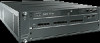
back. Figure 1-1 shows the front of the Cisco Nexus 5020 switch. Figure 1-1 Cisco Nexus 5020 Switch Front View 186260 1 2 1 Two power supplies 2 Five fan modules Figure 1-2 shows a close-up view of the front of the switch. Cisco Nexus 5000 Series Hardware Installation Guide 1-2 OL-15902-01 - HP Cisco MDS 9216i | Cisco Nexus 5000 Series Hardware Installation Guide (OL-159 - Page 17
port, and 2 AC power connectors. Figure 1-3 shows the rear of the Cisco Nexus 5020 switch. Figure 1-3 Cisco Nexus 5020 Switch Rear View 186265 1 2 3 4 56 1 System status LED 4 40 ) 3 Console port 6 AC power connectors OL-15902-01 Cisco Nexus 5000 Series Hardware Installation Guide 1-3 - HP Cisco MDS 9216i | Cisco Nexus 5000 Series Hardware Installation Guide (OL-159 - Page 18
[email protected] Figure 1-4 shows a close-up view of the rear of the Cisco Nexus 5020 chassis. Figure 1-4 Cisco Nexus 5020 Switch Rear View 1 2 186385 1 Internal cross connect ports Cisco Nexus 5000 Series Hardware Installation Guide 1-4 2 Network management ports OL-15902-01 - HP Cisco MDS 9216i | Cisco Nexus 5000 Series Hardware Installation Guide (OL-159 - Page 19
Cisco Nexus 5000 switches to be configured as cost-effective 10-Gigabit Ethernet switches and as I/O consolidation platforms with native Fibre Channel connectivity. The Cisco Nexus 5020 switch ports of 10-Gigabit Ethernet Cisco Data Center Ethernet and FCoE The chassis supports hot swapping of the - HP Cisco MDS 9216i | Cisco Nexus 5000 Series Hardware Installation Guide (OL-159 - Page 20
Nexus 5020 Switch Chapter 1 Product Overview Send documentation comments to [email protected] Figure Module The Ethernet expansion module supports six 10-Gigabit Ethernet ports, Six 10-Gigabit Ethernet ports Cisco Nexus 5000 Series Hardware Installation Guide 1-6 56 2 Module LED OL- - HP Cisco MDS 9216i | Cisco Nexus 5000 Series Hardware Installation Guide (OL-159 - Page 21
Switch Send documentation comments to [email protected] See Figure 1-12 for an illustration of how ports are grouped and numbered on the Ethernet expansion module. N5K-M1008 The N5K-M1008 GEM supports ports 2 LED OL-15902-01 Cisco Nexus 5000 Series Hardware Installation Guide 1-7 - HP Cisco MDS 9216i | Cisco Nexus 5000 Series Hardware Installation Guide (OL-159 - Page 22
1 Product Overview Send documentation comments to [email protected] Ports Each individual port on the Cisco Nexus 5020 switch is numbered, and groups of ports are numbered and the Ethernet expansion module ports. Cisco Nexus 5000 Series Hardware Installation Guide 1-8 OL-15902-01 - HP Cisco MDS 9216i | Cisco Nexus 5000 Series Hardware Installation Guide (OL-159 - Page 23
5020 switch is fully functional with one power supply. Figure 1-13 shows the power supply, which has two LEDs: one for power status and one for failure condition. Figure 1-13 Power Supply for the Cisco Nexus 5020 Switch 186264 OL-15902-01 12 Cisco Nexus 5000 Series Hardware Installation Guide - HP Cisco MDS 9216i | Cisco Nexus 5000 Series Hardware Installation Guide (OL-159 - Page 24
to cover the empty slot. Figure 1-14 shows a blank power supply filler panel. Figure 1-14 Blank Power Supply Filler Panel 186854 Fan Module The Cisco Nexus 5020 switch has five fans modules. Figure 1-15 shows the fan module. 1-10 Cisco Nexus 5000 Series Hardware Installation Guide OL-15902-01 - HP Cisco MDS 9216i | Cisco Nexus 5000 Series Hardware Installation Guide (OL-159 - Page 25
Chapter 1 Product Overview Nexus 5020 Switch Send documentation comments to [email protected] Figure 1-15 Cisco Nexus 5020 Fan Module 186263 1 1 Fan module LED The bicolor fan module LED indicates fan tray health. Green indicates normal operation, while amber indicates a fan - HP Cisco MDS 9216i | Cisco Nexus 5000 Series Hardware Installation Guide (OL-159 - Page 26
to [email protected] LED Descriptions Table 1-3 describes the LEDs for the Cisco Nexus 5020 switch. Table 1-3 LEDs for the Cisco Nexus 5020 Switch LED Chassis module has runtime failure and is brought offline. 1-12 Cisco Nexus 5000 Series Hardware Installation Guide OL-15902-01 - HP Cisco MDS 9216i | Cisco Nexus 5000 Series Hardware Installation Guide (OL-159 - Page 27
Chapter 1 Product Overview Nexus 5020 Switch Send documentation comments to [email protected] Table 1-3 LEDs for the Cisco Nexus 5020 Switch (continued) LED Location Power port is faulty and has been disabled. OL-15902-01 Cisco Nexus 5000 Series Hardware Installation Guide 1-13 - HP Cisco MDS 9216i | Cisco Nexus 5000 Series Hardware Installation Guide (OL-159 - Page 28
on the electrical interface and duplex LC connector on the optical interface.The Cisco Nexus 5020 switch supports the SFP-10G-SR transceiver. Model SFP-10G-SR Description 10-Gigabit Ethernet 5m, 26-28 AWG • 7m, 24-26 AWG 1-14 Cisco Nexus 5000 Series Hardware Installation Guide OL-15902-01 - HP Cisco MDS 9216i | Cisco Nexus 5000 Series Hardware Installation Guide (OL-159 - Page 29
Cable 7 Meter SFP Fiber Channel Transceivers The Cisco Nexus 5020 switch also supports the following SFP Fibre Channel transceiver: Model Module, page 1-26 • LED Descriptions, page 1-27 • Supported SFP Transceivers, page 1-28 OL-15902-01 Cisco Nexus 5000 Series Hardware Installation Guide 1-15 - HP Cisco MDS 9216i | Cisco Nexus 5000 Series Hardware Installation Guide (OL-159 - Page 30
modules on the front of the switch. Ports are at the rear of the switch. The airflow is front to back. Figure 1-17 shows the front of the Cisco Nexus 5010 switch. Figure 1-17 Cisco Nexus 5010 Switch Front View 189949 1 2 1-16 Cisco Nexus 5000 Series Hardware Installation Guide OL-15902-01 - HP Cisco MDS 9216i | Cisco Nexus 5000 Series Hardware Installation Guide (OL-159 - Page 31
with 2 cross-connect ports and 2 management ports, a console port, and 2 AC power connectors. Figure 1-19 shows the rear of the Cisco Nexus 5010 switch. Figure 1-19 Cisco Nexus 5010 Switch Rear View 1 2 3 4 5 6 189951 OL-15902-01 Cisco Nexus 5000 Series Hardware Installation Guide 1-17 - HP Cisco MDS 9216i | Cisco Nexus 5000 Series Hardware Installation Guide (OL-159 - Page 32
Nexus 5010 Switch Chapter 1 Product Overview Send documentation comments to [email protected] 1 System status LED 4 20 fixed 10-Gigabit Ethernet ports 2 (top and bottom) 3 Console port 6 AC power connectors 1-18 Cisco Nexus 5000 Series Hardware Installation Guide OL-15902-01 - HP Cisco MDS 9216i | Cisco Nexus 5000 Series Hardware Installation Guide (OL-159 - Page 33
Figure 1-20 shows a close-up view of the rear of the Cisco Nexus 5010 chassis. Figure 1-20 Cisco Nexus 5010 Switch Rear View Close-up 189952 1 23 4 5 6 1 System status cross connect ports 2 Network management ports OL-15902-01 Cisco Nexus 5000 Series Hardware Installation Guide 1-19 - HP Cisco MDS 9216i | Cisco Nexus 5000 Series Hardware Installation Guide (OL-159 - Page 34
Cisco Nexus 5000 switches to be configured as cost-effective 10-Gigabit Ethernet switches and as I/O consolidation platforms with native Fibre Channel connectivity. The Cisco Nexus 5010 switch The chassis supports hot swapping of the expansion modules. N5K-M1404 The N5K-M1404 GEM supports four SFP+ - HP Cisco MDS 9216i | Cisco Nexus 5000 Series Hardware Installation Guide (OL-159 - Page 35
Product Overview Nexus 5010 Switch Send documentation comments to [email protected] Figure 1-23 Ethernet ports 2 Module LED 3 Four 1-, 2-, 4-Gbps Fibre Channel ports The N5K-M1600 GEM supports 6 10G SFP+ based uplink connections. Figure 1-24 shows the N5K-M1600 GEM. Figure 1-24 - HP Cisco MDS 9216i | Cisco Nexus 5000 Series Hardware Installation Guide (OL-159 - Page 36
Nexus 5010 Switch Chapter 1 Product Overview Send documentation comments to [email protected] See Figure 1-12 for an illustration of how ports are grouped and numbered on the Ethernet expansion module. N5K-M1008 The N5K-M1008 GEM supports 8 1/2/4G Fiber Channel, SFP based uplink - HP Cisco MDS 9216i | Cisco Nexus 5000 Series Hardware Installation Guide (OL-159 - Page 37
ports are numbered top to bottom and left to right. There are 20-28 ports on the Cisco Nexus 5010 switch, depending on which GEM is installed. The 20 fixed ports form group 1 and are named with the N5K-M1600 GEM installed. OL-15902-01 Cisco Nexus 5000 Series Hardware Installation Guide 1-23 - HP Cisco MDS 9216i | Cisco Nexus 5000 Series Hardware Installation Guide (OL-159 - Page 38
Send documentation comments to [email protected] Figure 1-28 Port Numbering of the Cisco Nexus 5010 switch configured with the N5K-M1600 GEM with the N5K-M1008 GEM installed. Figure 1-29 Port Numbering of the Cisco Nexus 5010 switch configured with the N5K-M1008 GEM A B C D 1 3 - HP Cisco MDS 9216i | Cisco Nexus 5000 Series Hardware Installation Guide (OL-159 - Page 39
has slots for two power supplies. Two power supplies can be used for redundancy, but the Cisco Nexus 5010 switch is fully functional with one power supply. Figure 1-30 shows the power supply, which has . Fail LED Status Off On OL-15902-01 Cisco Nexus 5000 Series Hardware Installation Guide 1-25 - HP Cisco MDS 9216i | Cisco Nexus 5000 Series Hardware Installation Guide (OL-159 - Page 40
Nexus 5010 Switch Chapter 1 Product Overview Send documentation comments to [email protected] Table 1-5 Power panel. Figure 1-31 Blank Power Supply Filler Panel 186854 Fan Module The Cisco Nexus 5010 switch has slots for two fans modules. Each fan module houses six fans. The - HP Cisco MDS 9216i | Cisco Nexus 5000 Series Hardware Installation Guide (OL-159 - Page 41
operation normally Switch is powered off Fault condition Fan Tray Status Fan trays (front) Fan tray Green heath indicator (multi color) Amber Solid On Fan tray operating normally Solid On Fan failure within the fan tray OL-15902-01 Cisco Nexus 5000 Series Hardware Installation Guide 1-27 - HP Cisco MDS 9216i | Cisco Nexus 5000 Series Hardware Installation Guide (OL-159 - Page 42
the product you look at, the LED could be off, or solid amber. Blinks based on network activity Supported SFP Transceivers The Cisco Nexus 5010 switch supports both SFP+ Ethernet transceivers and SFP Fibre Channel transceivers. 1-28 Cisco Nexus 5000 Series Hardware Installation Guide OL-15902-01 - HP Cisco MDS 9216i | Cisco Nexus 5000 Series Hardware Installation Guide (OL-159 - Page 43
Switch Send documentation comments to nx5000-docfeedback@cisco LC connector on the optical interface.The Cisco Nexus 5010 switch supports the following SFP+ optical transceivers: • 7 Meter SFP Fiber Channel Transceivers The Cisco Nexus 5010 switch supports the multimode 850nm 4Gbps SFP with 150m - HP Cisco MDS 9216i | Cisco Nexus 5000 Series Hardware Installation Guide (OL-159 - Page 44
Nexus 5010 Switch Chapter 1 Product Overview Send documentation comments to [email protected] 1-30 Cisco Nexus 5000 Series Hardware Installation Guide OL-15902-01 - HP Cisco MDS 9216i | Cisco Nexus 5000 Series Hardware Installation Guide (OL-159 - Page 45
• Repacking the Cisco Nexus 5000 Switch for Return Shipment, page 2-26 Note Before you install, operate, or service the system, read the Regulatory Compliance and Safety Information for the Cisco Nexus 5000 Family for important safety information. Warning IMPORTANT SAFETY INSTRUCTIONS This warning - HP Cisco MDS 9216i | Cisco Nexus 5000 Series Hardware Installation Guide (OL-159 - Page 46
- The EIA Shelf Bracket Kit (an optional kit, purchased separately) For instructions on installing the switch using the rack-mount kit shipped with the switch, see the "Installing the Cisco Nexus 5020 Chassis in a Cabinet or Rack" section on page 2-5. Note The optional EIA Shelf Bracket Kit is - HP Cisco MDS 9216i | Cisco Nexus 5000 Series Hardware Installation Guide (OL-159 - Page 47
install and configure the switch. • Ensure that there is adequate space around the switch to allow for servicing the switch and for adequate supplying power to the switch are within the current ratings for the wiring and breakers. OL-15902-01 Cisco Nexus 5000 Series Hardware Installation Guide 2-3 - HP Cisco MDS 9216i | Cisco Nexus 5000 Series Hardware Installation Guide (OL-159 - Page 48
• Wire-stripping tool Unpacking and Inspecting the Switch Caution When handling switch components, wear an ESD strap and handle service representative and verify that you have received all items, including the following: • Print documentation Cisco Nexus 5000 Series Hardware Installation Guide - HP Cisco MDS 9216i | Cisco Nexus 5000 Series Hardware Installation Guide (OL-159 - Page 49
. Table 2-1 Cisco Nexus 5020 Switch Rack-Mount Kit Quantity 2 16 2 12 12 2 Part Description Rack-mount brackets M4x0.7 x 8-mm Phillips countersunk screws Rack-mount guides 10-32 Rack Nuts 10-32 x 3/4-inch Phillips countersunk screws Slider rails OL-15902-01 Cisco Nexus 5000 Series Hardware - HP Cisco MDS 9216i | Cisco Nexus 5000 Series Hardware Installation Guide (OL-159 - Page 50
-mount bracket on the other side of the switch. Figure 2-1 Attaching Front Rack-Mount Bracket to the Cisco Nexus 5020 switch 186363 2 3 1 1 Front rack-mount bracket 2 Rack-mount guides 3 Slider rail Step 2 Install the rack-mount guides on the switch as follows: a. Position one of the rack - HP Cisco MDS 9216i | Cisco Nexus 5000 Series Hardware Installation Guide (OL-159 - Page 51
documentation comments to [email protected] Figure 2-2 Installing the Slider Rails 186412 Step 4 Insert the switch into the rack: a. Using both hands, position the switch with the back of the switch between the front posts of the rack. b. Align the two rack-mount guides on either side of - HP Cisco MDS 9216i | Cisco Nexus 5000 Series Hardware Installation Guide (OL-159 - Page 52
Nexus 5010 Switch Rack-Mount Kit Quantity 2 12 2 10 10 2 Part Description Rack-mount brackets M4x0.7 x 8-mm Phillips countersunk screws Rack-mount guides 10-32 Rack Nuts 10-32 x 3/4-inch Phillips countersunk screws Slider rails Cisco Nexus 5000 Series Hardware Installation Guide 2-8 OL-15902 - HP Cisco MDS 9216i | Cisco Nexus 5000 Series Hardware Installation Guide (OL-159 - Page 53
-mount bracket on the other side of the switch. Figure 2-5 Attaching Front Rack-Mount Bracket to the Cisco Nexus 5010 switch 273161 3 2 1 1 Front rack-mount bracket 2 Rack-mount guides 3 Slider rail Step 2 Install the rack-mount guides on the switch as follows: a. Position one of the rack - HP Cisco MDS 9216i | Cisco Nexus 5000 Series Hardware Installation Guide (OL-159 - Page 54
mount guides on either side of the switch with the slider rails installed in the rack. Slide the rack-mount glides onto the slider rails, and then gently slide the switch all the way into the rack. This procedure is the same as that for the Cisco Nexus 5020 switch. See Figure 2-3. If the switch does - HP Cisco MDS 9216i | Cisco Nexus 5000 Series Hardware Installation Guide (OL-159 - Page 55
Cisco Nexus 5000 Switch Grounding the System Send documentation comments to nexus5kdocs@cisco contains a standard office environment. Electromagnetic noise problems are not anticipated, but installing a grounding standard office environment. Electromagnetic noise problems are not anticipated, but - HP Cisco MDS 9216i | Cisco Nexus 5000 Series Hardware Installation Guide (OL-159 - Page 56
Installing the Cisco Nexus 5000 Switch Send documentation comments to [email protected] Note the System Ground" section on page 2-14 for installation instructions and location of the chassis system ground pads. Note You Cisco Nexus 5000 Series Hardware Installation Guide OL-15902-01 - HP Cisco MDS 9216i | Cisco Nexus 5000 Series Hardware Installation Guide (OL-159 - Page 57
Chapter 2 Installing the Cisco Nexus 5000 Switch Grounding the System Send documentation comments to [email protected] Step 2 Step 3 Grasp the spring or view of grounding lug (clip slid behind screw) 4 Clip installed (behind screw) Cisco Nexus 5000 Series Hardware Installation Guide 2-13 - HP Cisco MDS 9216i | Cisco Nexus 5000 Series Hardware Installation Guide (OL-159 - Page 58
is required for U.S. installations. Commercially available 6 AWG wire is recommended. The length of the grounding wire depends on the proximity of the switch to proper grounding facilities. • No. 1 Phillips screwdriver. 2-14 Cisco Nexus 5000 Series Hardware Installation Guide OL-15902-01 - HP Cisco MDS 9216i | Cisco Nexus 5000 Series Hardware Installation Guide (OL-159 - Page 59
Figure 2-8 shows the system ground location on the Cisco Nexus 5020 switch. It is identical for the Cisco Nexus 5010 switch. Warning When installing or replacing the unit, the to protective earth ground at the service equipment. OL-15902-01 Cisco Nexus 5000 Series Hardware Installation Guide 2-15 - HP Cisco MDS 9216i | Cisco Nexus 5000 Series Hardware Installation Guide (OL-159 - Page 60
the Cisco Nexus 5000 Switch Send documentation comments to [email protected] Figure 2-8 Location of System Ground on a Cisco Nexus 5000 Switch 186483 2 1 3 6 1 ESD socket (on switch) 2 cable in the grounding lug. 2-16 Cisco Nexus 5000 Series Hardware Installation Guide OL-15902-01 - HP Cisco MDS 9216i | Cisco Nexus 5000 Series Hardware Installation Guide (OL-159 - Page 61
Note Do not connect the Ethernet port to the LAN until the initial switch configuration has been performed. For instructions on configuring the switch, see the Cisco Nexus 5000 Series CLI Configuration Guide. For instructions on connecting to the console port, see the "Connecting to the Console Port - HP Cisco MDS 9216i | Cisco Nexus 5000 Series Hardware Installation Guide (OL-159 - Page 62
that the system software has booted and the switch has initialized without error messages. If any problems occur, see Appendix E, "Troubleshooting Hardware Components". If you cannot resolve an issue, contact your customer service representative. Complete the worksheets provided in Appendix D, "Site - HP Cisco MDS 9216i | Cisco Nexus 5000 Series Hardware Installation Guide (OL-159 - Page 63
Cisco Nexus 5000 Switch Removing and Installing Components Send documentation comments to nexus5kdocs@cisco only. Note Install the Cisco Nexus 5000 switch in the rack before module and place your other hand under the module to support it. Gently slide the module into the opening until you - HP Cisco MDS 9216i | Cisco Nexus 5000 Series Hardware Installation Guide (OL-159 - Page 64
Removing and Installing Components Chapter 2 Installing the Cisco Nexus 5000 Switch Send documentation comments to [email protected] Figure 2-9 Positioning the Module in the Cisco Nexus 5020 Chassis 186598 Figure 2-10 shows the positioning of an expansion module in the 5010 chassis. - HP Cisco MDS 9216i | Cisco Nexus 5000 Series Hardware Installation Guide (OL-159 - Page 65
the slot will remain empty. Removing and Installing Power Supplies The Cisco Nexus 5000 switch supports two front-end power supplies, but it may be used with power supply to support it while you slide it out of the chassis. OL-15902-01 Cisco Nexus 5000 Series Hardware Installation Guide 2-21 - HP Cisco MDS 9216i | Cisco Nexus 5000 Series Hardware Installation Guide (OL-159 - Page 66
remain empty. Figure 2-11 Removing the Power Supply for the Cisco Nexus 5020 switch Figure 2-12 Removing the Power Supply for the 5010 273163 connection instructions, see the "Grounding the System" section on page 2-10. 2-22 Cisco Nexus 5000 Series Hardware Installation Guide OL-15902 - HP Cisco MDS 9216i | Cisco Nexus 5000 Series Hardware Installation Guide (OL-159 - Page 67
Cisco Nexus 5000 Switch Removing and Installing Components Send documentation comments to nexus5kdocs@cisco. may need the optional jumper power cord to connect the Cisco Nexus 5000 switch to your outlet receptacle. See the "Jumper Power for the Cisco Nexus 5010 switch, page 2-24 • Installing a Fan - HP Cisco MDS 9216i | Cisco Nexus 5000 Series Hardware Installation Guide (OL-159 - Page 68
Nexus 5010 switch 273164 Removing a Fan Module Warning When removing the fan tray, keep your hands and fingers away from the spinning fan blades. Let the fan blades completely stop before you remove the fan tray. Statement 258 2-24 Cisco Nexus 5000 Series Hardware Installation Guide OL-15902 - HP Cisco MDS 9216i | Cisco Nexus 5000 Series Hardware Installation Guide (OL-159 - Page 69
of the rails and fall out of the rack. To remove the Cisco Nexus 5000 switch from a rack, follow these steps: Step 1 Step 2 Step 3 Step 4 Ensure that the weight of the Cisco Nexus 5000 switch is fully supported and that the switch is being held by another person. Disconnect the power cord and the - HP Cisco MDS 9216i | Cisco Nexus 5000 Series Hardware Installation Guide (OL-159 - Page 70
" section on page 2-25, and repack it for shipment. If possible, use the original packing materials and container to repack the switch. Contact your Cisco customer service representative to arrange for return shipment to Cisco. 2-26 Cisco Nexus 5000 Series Hardware Installation Guide OL-15902-01 - HP Cisco MDS 9216i | Cisco Nexus 5000 Series Hardware Installation Guide (OL-159 - Page 71
Send documentation comments to [email protected] 3 C H A P T E R Connecting the Cisco Nexus 5000 Switch The Cisco Nexus 5000 switch provides the following types of ports: • • Connecting to a Fibre Channel Port, page 3-7 OL-15902-01 Cisco Nexus 5000 Series Hardware Installation Guide 3-1 - HP Cisco MDS 9216i | Cisco Nexus 5000 Series Hardware Installation Guide (OL-159 - Page 72
a Cisco Nexus 5000 Switch 186705 You can use the console port to perform the following: • Configure the Cisco Nexus 5000 switch from the CLI. • Monitor network statistics and errors. • Configure SNMP agent parameters. • Download software updates. Cisco Nexus 5000 Series Hardware Installation Guide - HP Cisco MDS 9216i | Cisco Nexus 5000 Series Hardware Installation Guide (OL-159 - Page 73
support VT100 terminal emulation. The terminal emulation software (frequently an application such as HyperTerminal or Procomm Plus) makes communication between the Cisco Nexus 5000 switch . For configuration instructions, see the Cisco Nexus 5000 Series Switch Configuration Guide. The Ethernet - HP Cisco MDS 9216i | Cisco Nexus 5000 Series Hardware Installation Guide (OL-159 - Page 74
the Cisco Nexus 5000 Switch Send documentation comments to [email protected] 4 Attach an ESD-preventive wrist strap and follow its instructions for use. Remove the dust cover from the port cage ESD-preventive wrist strap and follow its instructions for use. If a cable is installed in - HP Cisco MDS 9216i | Cisco Nexus 5000 Series Hardware Installation Guide (OL-159 - Page 75
Chapter 3 Connecting the Cisco Nexus 5000 Switch Connecting to an Ethernet Port Send documentation comments to [email protected] b. Press the release latch on the cable, grasp the connector cage by inserting a clean cover. OL-15902-01 Cisco Nexus 5000 Series Hardware Installation Guide 3-5 - HP Cisco MDS 9216i | Cisco Nexus 5000 Series Hardware Installation Guide (OL-159 - Page 76
If the cable does not install easily, ensure that it is correctly positioned before continuing. For instructions on verifying connectivity, see the Cisco Nexus 5000 Switch Configuration Guide. Removing a Cable from an SFP+ Transceiver Caution When pulling a cable from a transceiver, grip the body - HP Cisco MDS 9216i | Cisco Nexus 5000 Series Hardware Installation Guide (OL-159 - Page 77
Chapter 3 Connecting the Cisco Nexus 5000 Switch Connecting to a Fibre Channel Port Send documentation comments to [email protected] Step 4 Insert a dust plug ESD-preventive wrist strap and follow its instructions for use. OL-15902-01 Cisco Nexus 5000 Series Hardware Installation Guide 3-7 - HP Cisco MDS 9216i | Cisco Nexus 5000 Series Hardware Installation Guide (OL-159 - Page 78
Chapter 3 Connecting the Cisco Nexus 5000 Switch Send documentation comments to [email protected] Step 2 2 Attach an ESD-preventive wrist strap and follow its instructions for use. If a cable is installed in the transceiver Cisco Nexus 5000 Series Hardware Installation Guide 3-8 OL-15902-01 - HP Cisco MDS 9216i | Cisco Nexus 5000 Series Hardware Installation Guide (OL-159 - Page 79
the Cisco Nexus 5000 Switch Connecting to a Fibre Channel Port Send documentation comments to nexus5kdocs@cisco. Step 4 Attach an ESD-preventive wrist strap and follow its instructions for use. Remove the dust cover from the connector on the Cisco Nexus 5000 Series Hardware Installation Guide 3-9 - HP Cisco MDS 9216i | Cisco Nexus 5000 Series Hardware Installation Guide (OL-159 - Page 80
the cable does not install easily, ensure that it is correctly positioned before continuing. For instructions on verifying connectivity, see the Cisco Nexus 5000 Series CLI Configuration Guide. Removing a Cable from an SFP Transceiver Caution When pulling a cable from a transceiver, grip the body - HP Cisco MDS 9216i | Cisco Nexus 5000 Series Hardware Installation Guide (OL-159 - Page 81
Chapter 3 Connecting the Cisco Nexus 5000 Switch Connecting to a Fibre Channel Port Send documentation comments to [email protected] Maintaining SFP Transceivers and Fiber-Optic Cables to determine if damage has occurred. OL-15902-01 Cisco Nexus 5000 Series Hardware Installation Guide 3-11 - HP Cisco MDS 9216i | Cisco Nexus 5000 Series Hardware Installation Guide (OL-159 - Page 82
Connecting to a Fibre Channel Port Chapter 3 Connecting the Cisco Nexus 5000 Switch Send documentation comments to [email protected] 3-12 Cisco Nexus 5000 Series Hardware Installation Guide OL-15902-01 - HP Cisco MDS 9216i | Cisco Nexus 5000 Series Hardware Installation Guide (OL-159 - Page 83
Send documentation comments to [email protected] A A P P E N D I X Cabinet and Rack Installation This appendix provides the requirements for cabinet and rack installation be two RU (rack units), equal to 3.50 inches (8.9 cm). OL-15902-01 Cisco Nexus 5000 Series Hardware Installation Guide A-1 - HP Cisco MDS 9216i | Cisco Nexus 5000 Series Hardware Installation Guide (OL-159 - Page 84
rack-mounting rails must be at least 17.75 inches (45.1 cm) if the rear of the switch is not attached to the rack. For four-post EIA racks, this is the distance between the .6 in. (600 mm) X 39.4 in. (1000 mm) (H x W x D) (42 RU) Cisco Nexus 5000 Series Hardware Installation Guide A-2 OL-15902-01 - HP Cisco MDS 9216i | Cisco Nexus 5000 Series Hardware Installation Guide (OL-159 - Page 85
Cabinet and Rack Installation Cable Management Guidelines Send documentation comments to [email protected] Requirements Specific to Solid-Walled Cabinets A solid-walled cabinet is defined or copper cables through the rack. OL-15902-01 Cisco Nexus 5000 Series Hardware Installation Guide A-3 - HP Cisco MDS 9216i | Cisco Nexus 5000 Series Hardware Installation Guide (OL-159 - Page 86
Cable Management Guidelines Appendix A Cabinet and Rack Installation Send documentation comments to [email protected] Cisco Nexus 5000 Series Hardware Installation Guide A-4 OL-15902-01 - HP Cisco MDS 9216i | Cisco Nexus 5000 Series Hardware Installation Guide (OL-159 - Page 87
module installed) Specification 1.72 in x 17.3 in (43.9 cm) x 30.0 in (76.2 cm) 35 lb (15.875 kg) Table B-3 lists the environmental specifications for the Cisco Nexus 5000 switch. OL-15902-01 Cisco Nexus 5000 Series Hardware Installation Guide B-1 - HP Cisco MDS 9216i | Cisco Nexus 5000 Series Hardware Installation Guide (OL-159 - Page 88
m) Expansion Module Specifications Table B-4 Physical Specifications for the Cisco Nexus 5020 Switch Expansion Modules Description Specification Weight 1 lb (0.5 kg) Power in (0.039m) x 4.00 in (0.101m) x 13.00 in (.330m) Cisco Nexus 5000 Series Hardware Installation Guide B-2 OL-15902-01 - HP Cisco MDS 9216i | Cisco Nexus 5000 Series Hardware Installation Guide (OL-159 - Page 89
reflect this capability. A new software release will be required to support this capability. Specifications for the Cisco Nexus 5010 Power Supply The power supplies connect to the system Off Off Fail LED Status (Amber) Off On OL-15902-01 Cisco Nexus 5000 Series Hardware Installation Guide B-3 - HP Cisco MDS 9216i | Cisco Nexus 5000 Series Hardware Installation Guide (OL-159 - Page 90
Min. Max. Unit TS -40 ºC TC 0 70 ºC RH VCCT,R 3.1 3.5 V General Specifications for Cisco Fibre Channel SFP Transceivers Table B-10 lists the general specifications for Cisco Fibre Channel SFP transceivers at 4 Gbps. Cisco Nexus 5000 Series Hardware Installation Guide B-4 OL-15902-01 - HP Cisco MDS 9216i | Cisco Nexus 5000 Series Hardware Installation Guide (OL-159 - Page 91
Table B-11 provides the maximum environmental and electrical ratings for Cisco Fibre Channel SFP transceivers. Table B-11 Environmental Conditions and Power absolute maximum ratings and the recommended operating conditions. OL-15902-01 Cisco Nexus 5000 Series Hardware Installation Guide B-5 - HP Cisco MDS 9216i | Cisco Nexus 5000 Series Hardware Installation Guide (OL-159 - Page 92
Transceiver Specifications Appendix B Technical Specifications Send documentation comments to [email protected] Cisco Nexus 5000 Series Hardware Installation Guide B-6 OL-15902-01 - HP Cisco MDS 9216i | Cisco Nexus 5000 Series Hardware Installation Guide (OL-159 - Page 93
can be ordered from your customer service representative. Accessory Kit for the Cisco Nexus 5010 Switch The Cisco Nexus 5010 switch accessory kit includes the following items: • 2 slider rails • 2 rack-mount guides • 2 rack-mount brackets OL-15902-01 Cisco Nexus 5000 Series Hardware Installation - HP Cisco MDS 9216i | Cisco Nexus 5000 Series Hardware Installation Guide (OL-159 - Page 94
lug kit • 1 ESD wrist strap Note Additional parts can be ordered from your customer service representative. Console Cable The console cable has a RJ-45, RS-232 connector on one 6 2 5 5 3 Signal Name CTS DSR ZXD GND GND TXD Cisco Nexus 5000 Series Hardware Installation Guide C-2 OL-15902-01 - HP Cisco MDS 9216i | Cisco Nexus 5000 Series Hardware Installation Guide (OL-159 - Page 95
comments to [email protected] Table C-1 Cable the pinouts for the console port on the Cisco Nexus 5020 switch. Table C-2 Console Port Pinouts Pin Signal 1 C-3 lists the pinouts for the console port on the Cisco Nexus 5010 switch. Table C-3 Console Port Pinouts Pin Signal 1 RTS 2 - HP Cisco MDS 9216i | Cisco Nexus 5000 Series Hardware Installation Guide (OL-159 - Page 96
switch are supported. Table C-4 lists the power cords for the Cisco Nexus 5020 switch and provides their lengths in feet and meters. Table C-4 Power Cords for the Cisco Nexus 5020 Switch C-7 2.5 Figure C-8 2.5 Figure C-9 Cisco Nexus 5000 Series Hardware Installation Guide C-4 OL-15902-01 - HP Cisco MDS 9216i | Cisco Nexus 5000 Series Hardware Installation Guide (OL-159 - Page 97
and Port Specifications Supported Power Cords and Plugs Send documentation comments to [email protected] Table C-4 Power Cords for the Cisco Nexus 5020 Switch (continued) Description CAB : EL 701 (IEC60320/C13) 186571 OL-15902-01 Cisco Nexus 5000 Series Hardware Installation Guide C-5 - HP Cisco MDS 9216i | Cisco Nexus 5000 Series Hardware Installation Guide (OL-159 - Page 98
Supported Power Cords and Plugs Appendix C Cable and Port Specifications Send documentation comments to [email protected] Figure C-3 CAB-9K10A-AU Cordset rating: 250 V Length: 8 ft 2 in. (2.5 m) Connector: VSCC15 186576 Cisco Nexus 5000 Series Hardware Installation Guide C-6 OL-15902-01 - HP Cisco MDS 9216i | Cisco Nexus 5000 Series Hardware Installation Guide (OL-159 - Page 99
Appendix C Cable and Port Specifications Supported Power Cords and Plugs Send documentation comments to [email protected] Figure C-6 SFS-250V-10A-ID OVE ft 2 in. (2.5 m) Connector C15M (EN60320/C15 ) 186574 113375 OL-15902-01 Cisco Nexus 5000 Series Hardware Installation Guide C-7 - HP Cisco MDS 9216i | Cisco Nexus 5000 Series Hardware Installation Guide (OL-159 - Page 100
Supported Power Cords and Plugs Appendix C Cable and Port Specifications Send documentation comments to [email protected] Figure C-9 CAB-9K10A-SW Plug: MP232-R Cordset -N5K6A-NA Connector: EL 701 (IEC60320/C13) 186568 Cisco Nexus 5000 Series Hardware Installation Guide C-8 OL-15902-01 - HP Cisco MDS 9216i | Cisco Nexus 5000 Series Hardware Installation Guide (OL-159 - Page 101
Appendix C Cable and Port Specifications Supported Power Cords and Plugs Send documentation comments to [email protected] 186570 Plug: NEMA 6-15P Cordset rating: 10 A, 250 V Length: CAB-IND-10A Connector: HS10S 186569 OL-15902-01 Cisco Nexus 5000 Series Hardware Installation Guide C-9 - HP Cisco MDS 9216i | Cisco Nexus 5000 Series Hardware Installation Guide (OL-159 - Page 102
5020 switch power supply, while the connector plugs into the receptacle of a power distribution unit for a cabinet. Figure C-16 CAB-C13-C14-JMPR, Jumper Power Cord Plug: SS10A Cordset rating 10A, 250V (686mm) Connector: HS10S 186569 C-10 Cisco Nexus 5000 Series Hardware Installation Guide - HP Cisco MDS 9216i | Cisco Nexus 5000 Series Hardware Installation Guide (OL-159 - Page 103
Information, page D-3 • Chassis and Module Information, page D-4 Note For information about how to query the switch for configuration information, see the Cisco Nexus 5000 Switch Configuration Guide. Site Preparation Checklist Planning the location and layout of your equipment rack or wiring closet - HP Cisco MDS 9216i | Cisco Nexus 5000 Series Hardware Installation Guide (OL-159 - Page 104
D Site Planning and Maintenance Records Send documentation comments to [email protected] Table D-1 Site Planning Checklist Task No. Planning Activity Verified AC source circuit. 2. UPS = uninterruptible power supply. Date Cisco Nexus 5000 Series Hardware Installation Guide D-2 OL-15902-01 - HP Cisco MDS 9216i | Cisco Nexus 5000 Series Hardware Installation Guide (OL-159 - Page 105
and Maintenance Records Contact and Site Information Send documentation comments to [email protected] 3. EMI = electromagnetic interference. 4. RFI = radio frequency interference (line 2) City State Zip code Country OL-15902-01 Cisco Nexus 5000 Series Hardware Installation Guide D-3 - HP Cisco MDS 9216i | Cisco Nexus 5000 Series Hardware Installation Guide (OL-159 - Page 106
Serial Number Product Number Table D-3 Network-Related Information Switch IP address Switch IP netmask Host name Domain name IP broadcast address Gateway The supervisor module and the interface module are not removable. Cisco Nexus 5000 Series Hardware Installation Guide D-4 OL-15902-01 - HP Cisco MDS 9216i | Cisco Nexus 5000 Series Hardware Installation Guide (OL-159 - Page 107
cisco.com E A P P E N D I X Troubleshooting Hardware Components This appendix describes how to identify and resolve problems that might occur with the hardware components of the Cisco Nexus 5000 switch • test pfmtest-SNMP-trap temp-sensor Switch Hardware Best Practices Use the recommendations in - HP Cisco MDS 9216i | Cisco Nexus 5000 Series Hardware Installation Guide (OL-159 - Page 108
Appendix E Troubleshooting Hardware Components Send documentation comments to [email protected] Installation Best Practices When installing the switch, follow these best practices: • Plan your site configuration and prepare the site before installing the chassis. • Verify that you have the - HP Cisco MDS 9216i | Cisco Nexus 5000 Series Hardware Installation Guide (OL-159 - Page 109
documentation comments to [email protected] Numerics 10-Gigabit 2-10 weight 2-2, B-1 OL-15902-01 INDEX Cisco Nexus 5020 switch connecting a system ground 2-14 description 1-1, 1-16 rack (procedure) 2-25 repacking for return 2-26 supported SFP transceivers 1-14, 1-28 system ground location ( - HP Cisco MDS 9216i | Cisco Nexus 5000 Series Hardware Installation Guide (OL-159 - Page 110
2-9 L LC-type cables connecting to Fibre Channel ports 3-10 LED descriptions power supplies B-3 switch 1-12, 1-27 N network connections preparing 3-2 P port numbering description 1-8, 1-23 power cords jumper power cord (figure) C-10 IN-2 Cisco 5000 Series Hardware Installation Guide OL-15902-01 - HP Cisco MDS 9216i | Cisco Nexus 5000 Series Hardware Installation Guide (OL-159 - Page 111
modules B-2 physical B-1, B-2 power supplies B-2, B-3 transceivers B-4 switch installation equipment required 2-4 guidelines 2-3 screw torques 2-4 T transceivers, supported SFPs. See SFP transceivers troubleshooting best practices E-1 OL-15902-01 Cisco 5000 Series Hardware Installation Guide IN-3 - HP Cisco MDS 9216i | Cisco Nexus 5000 Series Hardware Installation Guide (OL-159 - Page 112
Index Send documentation comments to [email protected] IN-4 Cisco 5000 Series Hardware Installation Guide OL-15902-01
-
 1
1 -
 2
2 -
 3
3 -
 4
4 -
 5
5 -
 6
6 -
 7
7 -
8
-
9
-
10
-
11
-
12
-
13
-
14
-
15
-
16
-
17
-
18
-
19
-
20
-
21
-
22
-
23
-
24
-
25
-
26
-
27
-
28
-
29
-
30
-
31
-
32
-
33
-
34
-
35
-
36
-
37
-
38
-
39
-
40
-
41
-
42
-
43
-
44
-
45
-
46
-
47
-
48
-
49
-
50
-
51
-
52
-
53
-
54
-
55
-
56
-
57
-
58
-
59
-
60
-
61
-
62
-
63
-
64
-
65
-
66
-
67
-
68
-
69
-
70
-
71
-
72
-
73
-
74
-
75
-
76
-
77
-
78
-
79
-
80
-
81
-
82
-
83
-
84
-
85
-
86
-
87
-
88
-
89
-
90
-
91
-
92
-
93
-
94
-
95
-
96
-
97
-
98
-
99
-
100
-
101
-
102
-
103
-
104
-
105
-
106
-
107
-
108
-
109
-
110
-
111
-
112
 |
 |

Send documentation comments to [email protected]
Americas Headquarters
Cisco Systems, Inc.
170 West Tasman Drive
San Jose, CA 95134-1706
USA
Tel: 408 526-4000
800 553-NETS (6387)
Fax: 408 527-0883
Cisco Nexus 5000 Series Hardware
Installation Guide
November 2008
Text Part Number: OL-15902-01