HP Cisco MDS 9216i Cisco MDS 9124e Fabric Switch for HP c-Class BladeSystem Us - Page 19
IMPORTANT, CAUTION, Table 6, scale: 2/3 = 1
 |
View all HP Cisco MDS 9216i manuals
Add to My Manuals
Save this manual to your list of manuals |
Page 19 highlights
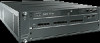
1. Locate the appropriate interconnect bay in the rear of the enclosure per the HP BladeSystem c7000 Enclosure setup and installation guide provided with your enclosure. 2. Remove the slot cover, if installed. IMPORTANT: Populate all enclosure I/O bays with the appropriate component; for example a switch, Pass-Thru, or one of the blank panels provided with the enclosure. CAUTION: Properly ground yourself before handling the switch. 3. Press the handle latch to release the installation handle. See Figure 4 and Table 6. scale: 2/3" = 1" 1 2 20 19 18 17 EXT 7 EXT 6 EXT5 181736 ! 3 Figure 4 Releasing the installation handle Table 6 Release mechanism components Item Description 1 Installation handle in latched position 2 Handle latch 3 Installation handle released 4. Align the Cisco MDS 9124e Fabric Switch with the appropriate interconnect bay according to your enclosure's specific configuration. 5. Push firmly into the interconnect bay. See Figure 5. Cisco MDS 9124e Fabric Switch for HP c-Class BladeSystem 19
-
 1
1 -
2
-
3
-
4
-
5
-
6
-
7
-
8
-
9
-
10
-
11
-
12
-
13
-
 14
14 -
 15
15 -
 16
16 -
 17
17 -
 18
18 -
 19
19 -
 20
20 -
 21
21 -
 22
22 -
 23
23 -
 24
24 -
25
-
26
-
27
-
28
-
29
-
30
-
31
-
32
-
33
-
34
-
35
-
36
-
37
-
38
-
39
-
40
-
41
-
42
-
43
-
44
-
45
-
46
-
47
-
48
-
49
-
50
-
51
-
52
-
53
-
54
-
55
-
56
-
57
-
58
-
59
-
60
-
61
-
62
-
63
-
64
-
65
-
66
-
67
-
68
 |
 |
