HP Cluster Platform Cabling Tables v2010 HP Cluster Platform ProLiant G6 and G - Page 69
Installing an HP BladeSystem c-Class InfiniBand Switch Module
 |
View all HP Cluster Platform Cabling Tables v2010 manuals
Add to My Manuals
Save this manual to your list of manuals |
Page 69 highlights
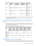
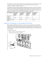
the InfiniBand switch module must be installed in the corresponding interconnect module bays (bays 3 and 4, bays 5 and 6, or bays 7 and 8). For more information about interconnect bay numbering, see "Interconnect module bay numbering (on page 67)." A full-height server blade can support an additional InfiniBand mezzanine option in mezzanine 3 connector, along with a second double-wide InfiniBand switch module installed in interconnect bays 7 and 8 in the rear of the enclosure. In this configuration, a full-height server blade configuration can be viewed as having a 1:1 I/O ratio. The table below lists the bandwidth (BW) ratios of different server blade types for various c-Class InfiniBand switch modules used in HP Cluster Platform BladeSystem configurations. Server blade type One 24-port IB module per enclosure Single density, full-height Single density, half-height 1:1 BW 2:1 BW Double density, half - height Two 24-port IB modules per enclosure - 1:1 BW 2:1 BW One 32-port IB module per enclosure 1:1 BW 2:1 BW - Two 32-port IB modules per enclosure - - 1:1 BW Installing an HP BladeSystem c-Class InfiniBand Switch Module Before installing an InfiniBand switch module in an enclosure, it may be necessary to remove the cable bracket, if installed. If the cable bracket must be removed, reverse the installation procedure described in the HP BladeSystem c-Class Enclosure Cable Management Bracket Installation Guide. In most instances, it is not necessary to remove the cables from the bracket. However, it might be necessary to remove the cables from the switch module. To install the switch module: 1. Remove any devices or blanks installed in the bay. 2. Remove the device bay divider, if installed. HP ProLiant BL c-Class Server Blades 69
-
 1
1 -
2
-
3
-
4
-
5
-
6
-
7
-
8
-
9
-
10
-
11
-
12
-
13
-
14
-
15
-
16
-
17
-
18
-
19
-
20
-
21
-
22
-
23
-
24
-
25
-
26
-
27
-
28
-
29
-
30
-
31
-
32
-
33
-
34
-
35
-
36
-
37
-
38
-
39
-
40
-
41
-
42
-
43
-
44
-
45
-
46
-
47
-
48
-
49
-
50
-
51
-
52
-
53
-
54
-
55
-
56
-
57
-
58
-
59
-
60
-
61
-
62
-
63
-
 64
64 -
 65
65 -
 66
66 -
 67
67 -
 68
68 -
 69
69 -
 70
70 -
 71
71 -
 72
72 -
 73
73 -
 74
74 -
75
-
76
-
77
-
78
-
79
-
80
-
81
-
82
-
83
-
84
-
85
-
86
-
87
-
88
-
89
-
90
-
91
-
92
-
93
-
94
 |
 |
