HP Color LaserJet Enterprise CP5520 User Guide
HP Color LaserJet Enterprise CP5520 Manual
 |
View all HP Color LaserJet Enterprise CP5520 manuals
Add to My Manuals
Save this manual to your list of manuals |
HP Color LaserJet Enterprise CP5520 manual content summary:
- HP Color LaserJet Enterprise CP5520 | User Guide - Page 1
Removal and replacement ● Introduction ● Removal and replacement strategy ● Electrostatic discharge ● Required tools ● Service approach ● Removal and replacement procedures ENWW 1 DRAFT - HP Color LaserJet Enterprise CP5520 | User Guide - Page 2
HP does not support repairing individual subassemblies or troubleshooting to the component level. Note the length, diameter, color lance points, or wire-harness guides and retainers. Removal and replacement strategy removing product parts. Always perform service work at an ESD-protected workstation - HP Color LaserJet Enterprise CP5520 | User Guide - Page 3
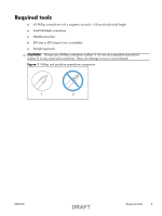
Required tools ● #2 Phillips screwdriver with a magnetic tip and a 152-mm (6-inch) shaft length ● Small flat blade screwdriver ● Needle-nose pliers ● ESD mat or ESD strap (if one is available) ● Penlight (optional) CAUTION: Always use a Phillips screwdriver (callout 1). Do not use a pozidrive - HP Color LaserJet Enterprise CP5520 | User Guide - Page 4
chassis before touching an ESD-sensitive part. ● Remove the print cartridges. See Print cartridges on page 5. ● Remove the tray cassette or cassettes. After performing service ● Plug in the power cable. ● Reinstall the print cartridges. ● Reinstall the tray cassette or cassettes. ● If the 1 x 500 - HP Color LaserJet Enterprise CP5520 | User Guide - Page 5
page 47 for information about removing service assemblies. Print cartridges When a print cartridge approaches the end of its color of the cartridge that has reached the end of its estimated useful life. Replacement instructions are provided on the label on the print cartridge. CAUTION: If toner - HP Color LaserJet Enterprise CP5520 | User Guide - Page 6
2. Grasp the handle of the used print cartridge and pull out to remove. 3. Remove the new print cartridge from its protective bag. NOTE: Be careful not to damage the memory tag on the print cartridge. 6 Removal and replacement DRAFT ENWW - HP Color LaserJet Enterprise CP5520 | User Guide - Page 7
4. Grasp both sides of the print cartridge and distribute the toner by gently rocking the print cartridge. 5. Remove the orange protective cover from the print cartridge. Place the protective cover on the used print cartridge to protect it during shipping. CAUTION: Avoid prolonged exposure to light. - HP Color LaserJet Enterprise CP5520 | User Guide - Page 8
7. Close the front door. 8 Removal and replacement DRAFT ENWW - HP Color LaserJet Enterprise CP5520 | User Guide - Page 9
is designed for a single use. Do not try to empty the tonercollection unit and reuse it. To recycle a discarded toner-collection unit, follow the instructions that come with a replacment toner-collection unit. 1. Open the TCU access door (callout 1) on the product back side. 2. Grasp the top of the - HP Color LaserJet Enterprise CP5520 | User Guide - Page 10
4. Install the plug onto the discard TCU before putting it into the box and mailing it for recycling. Figure 4 Remove the toner-collection unit (3 of 3) 10 Removal and replacement DRAFT ENWW - HP Color LaserJet Enterprise CP5520 | User Guide - Page 11
Fuser CAUTION: The fuser might be hot. Allow enough time after turning off the product power for the fuser to cool. 1. Open the right-door assembly. 2. Grasp the handles and squeeze the blue release levers (callout 1). Figure 5 Remove the fuser 1 2 3. Pull the fuser (callout 2) straight out of the - HP Color LaserJet Enterprise CP5520 | User Guide - Page 12
: Do not touch the spongy roller surface unless you are replacing the roller. Skin oils on the roller can cause paper pickup problems. 1. Open Tray 1 (callout 1), and then remove the pickup roller cover (callout 2). Figure 6 Remove the pickup roller (Tray 1) (1 of 2) 1 2 2. Spead out the pickup - HP Color LaserJet Enterprise CP5520 | User Guide - Page 13
: Do not touch the spongy roller surface unless you are replacing the roller. Skin oils on the roller can cause paper pickup problems. 1. Open Tray 1 (callout 1), and then remove the pickup roller cover (callout 2). Figure 8 Remove the separation pad (Tray 1) (1 of 4) 1 2 2. Take out the tool - HP Color LaserJet Enterprise CP5520 | User Guide - Page 14
3. Insert the tool under the separation pad. Figure 10 Remove the separation pad (Tray 1) (3 of 4) 4. Rotate the top of the tool away from the product to release the separation pad, and then remove the tool and the separation pad together. Figure 11 Remove the separation pad (Tray 1) (4 of 4) - HP Color LaserJet Enterprise CP5520 | User Guide - Page 15
CAUTION: Do not touch the spongy roller surface unless you are replacing the roller. Skin oils on the roller can cause paper pickup problems. 1. Remove Tray 2 from the product. 2. Open the right-door assembly. 3. On the separation roller assembly, slide the lever (callout 1) toward the unlocked icon - HP Color LaserJet Enterprise CP5520 | User Guide - Page 16
CAUTION: Do not touch the spongy roller surface unless you are replacing the roller. Skin oils on the roller can cause paper pickup problems. 1. Open Tray 2. 2. Open the right-door assembly. 3. Remove the separation roller assembly (see Separation roller assembly (Tray 2) on page 15) 4. Lift one of - HP Color LaserJet Enterprise CP5520 | User Guide - Page 17
paper feeders) CAUTION: Do not touch the spongy roller surface unless you are replacing the roller. Skin oils on the roller can cause paper pickup problems. TIP: You do not have to separate the product from the feeder to remove these rollers. 1. Remove the Tray 3 or Tray 4/5/6 cassette from the - HP Color LaserJet Enterprise CP5520 | User Guide - Page 18
touch the spongy roller surface unless you are replacing the roller. Skin oils on the roller can cause image quality problems. NOTE: If the secondary transfer roller is replaced, HP recommends that the ITB be replaced also. If both components are replaced at the same time, you must use the control - HP Color LaserJet Enterprise CP5520 | User Guide - Page 19
the black-plastic belt. Skin oils and fingerprints on the belt can cause printquality problems. Always place the ITB on a flat surface in a safe and protected location. NOTE: If the ITB assembly is replaced, HP recommends that the secondary transfer roller be replaced also. If both components are - HP Color LaserJet Enterprise CP5520 | User Guide - Page 20
3. Pull the ITB out of the product until two large handles expand along the right and left side of the ITB. Figure 19 Remove the intermediate transfer belt (2 of 3) 4. Grasp the large handles on the ITB and then pull the ITB straight out of the product until it stops, and then pull up to remove it - HP Color LaserJet Enterprise CP5520 | User Guide - Page 21
Reset the New Transfer Kit setting at the control panel NOTE: Use this procedure to reset the internal page count if a replacement ITB and secondary transfer roller are installed. 1. At the control panel, press the Home button . 2. Open the following menus: ● Administration ● Manage Supplies ● Reset - HP Color LaserJet Enterprise CP5520 | User Guide - Page 22
Formatter PCA CAUTION: ESD sensitive component. Do not replace the laser scanner and the formatter PCA at the same time. The settings for the laser scanner are stored in the formatter RAM. When you install a new laser scanner, it reads the settings from the formatter. Do not replace the DC - HP Color LaserJet Enterprise CP5520 | User Guide - Page 23
a configuration page and make sure that the serial number and page count information were transfered to the formatter PCA. If they were not, use the Service menu to reset these values. ENWW DRAFT Removal and replacement procedures 23 - HP Color LaserJet Enterprise CP5520 | User Guide - Page 24
Encrypted hard drive or solid-state hard drive Before proceeding, remove the following components: ● Formatter PCA. See Formatter PCA on page 22. Identify the hard drive type ❑ Encrypted hard drive (callout 1) 1 ❑ Solid-state hard drive (callout 1) 1 24 Removal and replacement DRAFT ENWW - HP Color LaserJet Enterprise CP5520 | User Guide - Page 25
two connectors (callout 1). Figure 23 Remove the EIO encrypted hard drive (1 of 3) 1 2. Release one tab (callout 1), and then slightly separate the hard-disk support arm from the PCA. Figure 24 Remove the EIO encrypted hard drive (2 of 3) 1 ENWW DRAFT Removal and replacement procedures 25 - HP Color LaserJet Enterprise CP5520 | User Guide - Page 26
3. Rotate the hard drive up and away from the PCA, and then slide it as shown below to remove it. Figure 25 Remove the EIO encrypted hard drive (3 of 3) 1 2 Remove the solid-state hard drive 1. Release the hard drive lock. Figure 26 Remove the solid-state hard drive (1 of 3) 26 Removal and - HP Color LaserJet Enterprise CP5520 | User Guide - Page 27
2. Remove the lock from the PCA. Figure 27 Remove the solid-state hard drive (2 of 3) 3. Disconnect the solid-state PCA from the formatter PCA, and then remove it. Figure 28 Remove the solid-state hard drive (3 of 3) ENWW DRAFT Removal and replacement procedures 27 - HP Color LaserJet Enterprise CP5520 | User Guide - Page 28
Covers Identification and location Figure 29 External panels, covers, and doors 5 4 3 9 1 2 6 8 Table 1 External panels, covers, and doors Item Description 1 Rear-right cover (see Right-rear cover on page 36) 2 Right-door assembly (see Right-door assembly on page 43) Item 6 7 7 - HP Color LaserJet Enterprise CP5520 | User Guide - Page 29
on page 33) Right-front cover and control-panel assembly on page 30) 4 Front-door assembly (see Front-door assembly 9 Toner collection unit access door (see Toner on page 40) collection unit access door on page 34) 5 Tray 2 cassette ENWW DRAFT Removal and replacement procedures 29 - HP Color LaserJet Enterprise CP5520 | User Guide - Page 30
Right-front cover and control-panel assembly 1. Open the front door and the right door. 2. Remove two screws (callout 1). Figure 30 Remove the right-front cover and control-panel assembly (1 of 3) 1 3. Release 3 tabs (callout 1) on the right side of the assembly. Figure 31 Remove the right-front - HP Color LaserJet Enterprise CP5520 | User Guide - Page 31
4. Support the assembly, release one cable retainer (callout 1), and then disconnect two connectors (callout 2). Remove the assembly. Figure 32 Remove the right-front cover and control-panel assembly (3 of 3) 2 1 ENWW DRAFT Removal and replacement procedures 31 - HP Color LaserJet Enterprise CP5520 | User Guide - Page 32
side of the cover, release six tabs (callout 2), and then remove the cover from the product. Figure 33 Remove the left cover 2 2 1 TIP: Opening the toner-collection door might make it easier to release the tabs on the left side of the cover. Reinstallation tip If the front door will not - HP Color LaserJet Enterprise CP5520 | User Guide - Page 33
Rear cover Remove the rear cover ▲ Remove five screws (callout 1), and then remove the cover from the product. Figure 34 Remove the rear cover 1 2 ENWW DRAFT Removal and replacement procedures 33 - HP Color LaserJet Enterprise CP5520 | User Guide - Page 34
collection unit, and then release the link arm (callout 2) on the left side of the door. Figure 35 Remove the toner collection unit access door (1 of 3) 2 1 2. Partially close the door so that the link arm (callout 1) can clear the stop (callout 2) on the door, and then - HP Color LaserJet Enterprise CP5520 | User Guide - Page 35
3. Rotate the access door down 90 degrees, and then pull on the right side of the door to remove the access door. Figure 37 Remove the toner collection unit access door (3 of 3) 1 2 ENWW DRAFT Removal and replacement procedures 35 - HP Color LaserJet Enterprise CP5520 | User Guide - Page 36
Right-rear cover 1. Remove the rear cover. See Rear cover on page 33. 2. Open the right-door assembly. 3. Remove two screws (callout 1), release one tab (callout 2), and then remove the cover. CAUTION: The ground spring on the back of the cover can easily be dislodged. Be careful not to lose it. See - HP Color LaserJet Enterprise CP5520 | User Guide - Page 37
Reinstall the right-rear cover ▲ Make sure that the ground spring (callout 1) is correctly installed before you reinstall the right-rear cover. Figure 39 Right-rear cover ground spring 1 ENWW DRAFT Removal and replacement procedures 37 - HP Color LaserJet Enterprise CP5520 | User Guide - Page 38
36. Remove the top cover 1. Open the right-door assembly, and then remove four screws (callout 1). Figure 40 Remove the top cover (1 of 2) 1 1 2. Open the toner-collection door. 38 Removal and replacement DRAFT ENWW - HP Color LaserJet Enterprise CP5520 | User Guide - Page 39
3. Release two tabs (callout 1), and then remove the cover. Figure 41 Remove the top cover (2 of 2) 2 1 ENWW DRAFT Removal and replacement procedures 39 - HP Color LaserJet Enterprise CP5520 | User Guide - Page 40
Front-door assembly 1. Remove the control panel. See Right-front cover and control-panel assembly on page 30. 2. Open the front door. 3. Remove one screw (callout 1) and the inner cover rail mount (callout 2). CAUTION: As shown in Figure 43 Remove the front-door assembly (2 of 4) on page 40, when - HP Color LaserJet Enterprise CP5520 | User Guide - Page 41
4. Close the inner cover, and then release two tabs on each stopper (callout 1) with a small flat-blade screwdriver. Figure 44 Remove the front-door assembly (3 of 4) 1 NOTE: Each tab is at the end of the stopper that is closest to the product. 2 1 ENWW DRAFT Removal and replacement procedures - HP Color LaserJet Enterprise CP5520 | User Guide - Page 42
5. Position the door as shown below, and then slide the front-door assembly in the direction that the arrow indicates to remove it from the product. Figure 45 Remove the front-door assembly (4 of 4) 1 42 Removal and replacement DRAFT ENWW - HP Color LaserJet Enterprise CP5520 | User Guide - Page 43
Right-door assembly Remove the following components: ● Rear cover (see Rear cover on page 33) ● Right rear cover (see Right-rear cover on page 36) 1. Open the right-door assembly 2. Remove one screw (callout 1), release the link arm (callout 2), and then disconnect two connector (callout 3). NOTE: - HP Color LaserJet Enterprise CP5520 | User Guide - Page 44
(callout 2). Figure 47 Remove the right-door assembly (2 of 6) 2 1 4. Release one tab (callout 1), and then remove the guide (callout 2). TIP: Release the wire harnesses from the guide as you remove it. Figure 48 Remove the right-door assembly (3 of 6) 1 2 44 Removal and replacement DRAFT ENWW - HP Color LaserJet Enterprise CP5520 | User Guide - Page 45
5. Disconnect two connectors (callout 1). Figure 49 Remove the right-door assembly (4 of 6) 1 6. Remove one screw (callout 1), and then release the link arm (callout 2). Figure 50 Remove the right-door assembly (5 of 6) 2 1 ENWW DRAFT Removal and replacement procedures 45 - HP Color LaserJet Enterprise CP5520 | User Guide - Page 46
7. Remove two screws (callout 1), remove the hinge (callout 2), and then slide the right-door assembly (callout 3) to the left to remove it. Figure 51 Remove the right-door assembly (6 of 6) 1 2 3 46 Removal and replacement DRAFT ENWW - HP Color LaserJet Enterprise CP5520 | User Guide - Page 47
the product. If necessary, remove the components listed at the beginning of a procedure before proceeding to service the product. Formatter case Before proceeding, remove the following components: ● Formatter PCA. See Formatter PCA on page 22. ● Left cover. See Left cover on page - HP Color LaserJet Enterprise CP5520 | User Guide - Page 48
2. Remove nine screws (callout 1), and then slide the formatter case unit (callout 2) away from the DC controller to remove it. Figure 53 Remove the formatter case assembly (2 of 2) 1 48 Removal and replacement DRAFT ENWW - HP Color LaserJet Enterprise CP5520 | User Guide - Page 49
Laser scanner assembly CAUTION: Do not replace the laser scanner and the formatter PCA at the same time. The settings for the laser scanner are stored in the formatter RAM. When you install a new laser scanner, it reads the settings from the formatter. Before proceeding, remove the following - HP Color LaserJet Enterprise CP5520 | User Guide - Page 50
55 Remove the laser scanner assembly (2 of 4) 1 2 3 4. Release one tab (callout 1), and then slide the cable guide (callout 2) in the direction that the arrow indicates. 5. Remove the cable guide (callout 2) and the flat cables (callout 3) together, and then remove one spring (callout 4). Figure 56 - HP Color LaserJet Enterprise CP5520 | User Guide - Page 51
touch the protective glass strip on top of the assembly. Figure 57 Remove the laser scanner assembly (4 of 4) 1 2 Reinstallation tip Align the assembly with the guides on the left side of the opening when reinstalling the assembly. Align the pin on the bottom of the assembly with the hole in the - HP Color LaserJet Enterprise CP5520 | User Guide - Page 52
Paper pickup assembly Before proceeding, remove the following components: ● Tray 2 cassette. ● Tray 2 separation roller assembly. See Separation roller assembly (Tray 2) on page 15. ● ITB. See Intermediate transfer belt (ITB) on page 19. Remove the paper pickup assembly 1. Open the right door, pull - HP Color LaserJet Enterprise CP5520 | User Guide - Page 53
might be hidden behind the assembly. Figure 59 Remove the paper pickup assembly (2 of 3) 1 3. Pull out one tab (callout 1), and then slide the guide (callout 2) to the right to remove it. Figure 60 Remove the paper pickup assembly (3 of 3) 2 1 ENWW DRAFT Removal and replacement procedures 53 - HP Color LaserJet Enterprise CP5520 | User Guide - Page 54
4. Remove two screws (callout 1), move the registration sensor lever (callout 2) to the up position, and then pull the paper pickup assembly (callout 3) toward you to remove it. Figure 61 Remove the paper pickup assembly (4 of 4) 2 3 1 54 Removal and replacement DRAFT ENWW - HP Color LaserJet Enterprise CP5520 | User Guide - Page 55
Reinstall the paper pickup assembly Use the steps below to reinstall the paper pickup assembly. If you are installing a replacement assembly, also see Installing a replacement paper pickup assembly on page 57 after completing these steps. 1. When reassembling the paper pickup assembly (callout 1), - HP Color LaserJet Enterprise CP5520 | User Guide - Page 56
2. Make sure that the sensor flag is correctly installed, and that the flag moves properly after reassembling the paper pickup assembly. Figure 63 Paper pickup assembly sensor flag correctly installed Figure 64 Paper pickup assembly sensor flag incorrectly installed 56 Removal and replacement - HP Color LaserJet Enterprise CP5520 | User Guide - Page 57
the Yes item, and then press the OK button. Reset the Media Sensor Value a. Press the Home button . b. Open the following menus: ● Device Maintenance ● Service ● Service Access Code c. Use the arrow buttons to enter the access code, and then press the OK button. ENWW DRAFT Removal and replacement - HP Color LaserJet Enterprise CP5520 | User Guide - Page 58
d. Press the Down arrow button to highlight the Media Sensor Value menu, and then press the OK button. Figure 65 Media sensor value label e. Use the arrow buttons to enter the media sensor value found on the replacement assembly. f. Press the OK button to save to save the value. 58 Removal and - HP Color LaserJet Enterprise CP5520 | User Guide - Page 59
Registration sensor assembly Before proceeding, remove the following components: ● Tray 2 cassette. ● Cassette separation roller assembly. See Separation roller assembly (Tray 2) on page 15. ● Intermediate transfer belt (ITB). See Intermediate transfer belt (ITB) on page 19. ● Cassette pickup drive - HP Color LaserJet Enterprise CP5520 | User Guide - Page 60
2. Disconnect one connector (callout 1), and then detach the bottom part of the spring (callout 2) at the right end. If necessary, use a pick or needle-nose pliers to detach the spring. Figure 67 Remove the registration sensor assembly (2 of 4) 1 2 3. Detach the bottom of one spring (callout 1) - HP Color LaserJet Enterprise CP5520 | User Guide - Page 61
4. Release one of the registration sensor unit pivot hinges from the shafts (callout 1), pull out that end of the assembly (callout 2), and then repeat the procedure on the other pivot hinge. Figure 69 Remove the registration sensor assembly (4 of 4) 2 1 ENWW DRAFT Removal and replacement - HP Color LaserJet Enterprise CP5520 | User Guide - Page 62
Lifter-drive assembly Before proceeding, remove the following components: ● Tray 2 cassette. ● Fuser. See Fuser on page 11. ● ITB. See Intermediate transfer belt (ITB) on page 19. ● 1 x 500-paper feeder. See 1 x 500-sheet paper feeder assembly on page 137. ● 3 x 500-paper feeder (optional accessory - HP Color LaserJet Enterprise CP5520 | User Guide - Page 63
2. Release the tab (callout 1), and then pull up to remove the cover (callout 2). Figure 71 Remove the lifter-drive assembly (2 of 3) 2 1 ENWW DRAFT Removal and replacement procedures 63 - HP Color LaserJet Enterprise CP5520 | User Guide - Page 64
3. Disconnect two connectors (callout 1), remove one screw (callout 2), and then remove the lifter drive unit (callout 3). Figure 72 Remove the lifter-drive assembly (3 of 3) 1 3 2 Reinstallation tip Make sure that the tabs align correctly when reinstalling the lifter-drive assembly. 64 Removal and - HP Color LaserJet Enterprise CP5520 | User Guide - Page 65
ITB front guide assembly Before proceeding, remove the following components: ● ITB. See Intermediate transfer belt (ITB) on page 19. arm (callout 2) to detach it from the product chassis. Figure 73 Remove the ITB front guide assembly (1 of 4) 2 1 ENWW DRAFT Removal and replacement procedures 65 - HP Color LaserJet Enterprise CP5520 | User Guide - Page 66
2. Remove three screws (callout 1), release four tabs (callout 2), and then remove the cartridge upper guide unit (callout 3). Figure 74 Remove the ITB front guide assembly (2 of 4) 3 1 2 3. Disconnect one connector (callout 1), and then release the cables (callout 3) from the cable clamp (callout - HP Color LaserJet Enterprise CP5520 | User Guide - Page 67
4. Release one tab (callout 1), and then slide the ITB front guide assembly (callout 2) in the direction that the arrow indicates to remove it. Figure 76 Remove the ITB front guide assembly (4 of 4) 1 2 ENWW DRAFT Removal and replacement procedures 67 - HP Color LaserJet Enterprise CP5520 | User Guide - Page 68
ITB rear guide assembly Before proceeding, remove the following components: ● ITB. See Intermediate transfer connector (callout 1), release one tab (callout 2), and then slide the ITB rear guide unit (callout 3) in the direction that the arrow indicates to remove it. Figure 77 Remove the ITB rear - HP Color LaserJet Enterprise CP5520 | User Guide - Page 69
control-panel assembly on page 30. ● Left cover. See Left cover on page 32. ● Rear cover. See Rear cover on page 33. ● Toner collection unit access door. See Toner collection unit access door on page 34. ● Right-rear cover. See Right-rear cover on page 36. ● Top cover. See Top cover on - HP Color LaserJet Enterprise CP5520 | User Guide - Page 70
2. Remove two M4-screws (callout 1) and one M3-screw (callout 2). Then remove the toner cover (callout 3). Figure 79 Remove the residual toner full sensor (2 of 4) 1 3 2 70 Removal and replacement DRAFT ENWW - HP Color LaserJet Enterprise CP5520 | User Guide - Page 71
3. Disconnect one connector (callout 1), remove three screws (callout 2), and then remove the residual toner full sensor assembly (callout 3). CAUTION: During the removal process, make sure that the white gear (callout 4) does not fall out of the assembly. The white - HP Color LaserJet Enterprise CP5520 | User Guide - Page 72
full sensor 1. If the white gear (callout 1) was removed with the residual toner full sensor assembly, carefully remove it from the assembly. Figure 82 Reinstall the residual toner full sensor (1 of 3) 1 2. Alight the flat portion of the gear with the corresponding flat portion of the drive shaft - HP Color LaserJet Enterprise CP5520 | User Guide - Page 73
3. Install the gear on the shaft before you install the residual toner full sensor assembly. Figure 84 Reinstall the residual toner full sensor (3 of 3) ENWW DRAFT Removal and replacement procedures 73 - HP Color LaserJet Enterprise CP5520 | User Guide - Page 74
on page 34. ● Right-rear cover. See Right-rear cover on page 36. ● Top cover. See Top cover on page 38. ● Residual-toner full sensor. See Residual toner full sensor on page 69. Remove the main drive assembly 1. Disconnect three connectors (callout 1) and one FFC (callout 2). Figure 85 Remove the - HP Color LaserJet Enterprise CP5520 | User Guide - Page 75
2. Remove one screw (callout 1), and then remove the sheet-metal plate (callout 2). Figure 86 Remove the main drive assembly (2 of 17) 1 2 3. Disconnect twenty-two connectors and six FFCs on the DC controller PCA (callout 1). TIP: Three connectors (callout 2) should be empty when the DC controller - HP Color LaserJet Enterprise CP5520 | User Guide - Page 76
callout 2). Figure 88 Remove the main drive assembly (4 of 17) 3 2 1 5. Release one tab (callout 1), and then remove the guide (callout 2). TIP: Release the wire harnesses from the guide as you remove it. Figure 89 Remove the main drive assembly (5 of 17) 1 2 76 Removal and replacement DRAFT ENWW - HP Color LaserJet Enterprise CP5520 | User Guide - Page 77
callout 1), and then remove the DC controller and the two sheet-metal support plates. CAUTION: Carefully unthread the FFCs from the plate to avoid damaging them when you remove the DC controller and the two sheet-metal support plates. Figure 90 Remove the main drive assembly (6 of 17) 1 ENWW DRAFT - HP Color LaserJet Enterprise CP5520 | User Guide - Page 78
7. Disconnect three connectors (callout 1), remove two screws (callout 2), release one wire retainer (callout 3), and then remove the driver PCA (callout 4). Figure 91 Remove the main drive assembly (7 of 17) 2 3 4 1 8. Remove one screw (callout 1), and then remove the second transfer high- - HP Color LaserJet Enterprise CP5520 | User Guide - Page 79
9. Release one tab (callout 1), and then remove the cover (callout 2). Figure 93 Remove the main drive assembly (9 of 17) 2 1 10. Remove one screw (callout 1), release four tabs (callout 2), and then remove the developing highvoltage power supply (callout 3). Reinstallation tip When you reinstall - HP Color LaserJet Enterprise CP5520 | User Guide - Page 80
side of the PCA. Figure 95 Remove the main drive assembly (11 of 17) 2 5 4 3 1 12. Remove two screws (callout 1), and then remove the sheet-metal support brackets (callout 2). Figure 96 Remove the main drive assembly (12 of 17) 2 1 80 Removal and replacement DRAFT ENWW - HP Color LaserJet Enterprise CP5520 | User Guide - Page 81
13. Disconnect one connector (callout 1), release one tab (callout 2), slide the cable guide (callout 3) to the left to release the it, and then move the guide to the side, out of the way. TIP: It might be easier to disconnect the connector if you release it from the holder. Figure 97 - HP Color LaserJet Enterprise CP5520 | User Guide - Page 82
sensor assembly. Figure 99 Remove the main drive assembly (15 of 17) 1 16. Disconnect six connectors (callout 1), and then release the wire harnesses from the guides (callout 2). Figure 100 Remove the main drive assembly (16 of 17) 1 2 82 Removal and replacement DRAFT ENWW - HP Color LaserJet Enterprise CP5520 | User Guide - Page 83
17. Remove six screws (callout 1), and then remove the main drive assembly (callout 2). NOTE: Make sure that the right door is closed. Figure 101 Remove the main drive assembly (17 of 17) 1 2 ENWW DRAFT Removal and replacement procedures 83 - HP Color LaserJet Enterprise CP5520 | User Guide - Page 84
Install the main drive assembly NOTE: Installing a replacement assembly: follow the instructions in this section. Reinstalling the original assembly: some of these instructions in this section do not apply (for example, removing the shipping spacers). Do not rotate the gears when handling the - HP Color LaserJet Enterprise CP5520 | User Guide - Page 85
2. With the right door closed, position the drive assembly near the product, and then rotate it up and onto the chassis. NOTE: Make sure that the right-door link arm shaft (callout 1) aligns with and is positioned in the hole (callout 2) on the arm on the drive assembly, and that the pins on the - HP Color LaserJet Enterprise CP5520 | User Guide - Page 86
4. From the top of the product, look at each shutter arm. Make sure that they are in the closed position (callout 1). If they are in the open position (callout 2), carefully push on the shutter to close them. Figure 105 Install the main drive assembly (4 of 8) 1 2 5. Make sure that the six sheet- - HP Color LaserJet Enterprise CP5520 | User Guide - Page 87
6. With the drive assembly correctly installed, verify the following: ● Open and close the front door. The OPC drum drive gears (callout 1; two shown, four total) must move in and out when viewed from inside the product. ● Open and close the right door. The ITB drive gear (callout 2) must move in - HP Color LaserJet Enterprise CP5520 | User Guide - Page 88
8. Reinstall the two small sheet-metal brackets. NOTE: The tab on the sheet-metal brackets must be inserted in the hole in the drive assembly chassis as shown below. Figure 109 Install the main drive assembly (8 of 8) 88 Removal and replacement DRAFT ENWW - HP Color LaserJet Enterprise CP5520 | User Guide - Page 89
door on page 34. ● Right-rear cover. See Right-rear cover on page 36. ● Top cover. See Top cover on page 38. ● Residual-toner full sensor. See Residual toner full sensor on page 69. ● Main drive assembly. See Main drive assembly on page 74. Remove the fuser drive assembly 1. Remove one screw - HP Color LaserJet Enterprise CP5520 | User Guide - Page 90
2. Disconnect two connectors (callout 1). Figure 111 Remove the fuser drive assembly (2 of 3) 1 3. Remove four screws (callout 1), and then remove the fuser drive assembly. Figure 112 Remove the fuser drive assembly (3 of 3) 1 90 Removal and replacement DRAFT ENWW - HP Color LaserJet Enterprise CP5520 | User Guide - Page 91
Install a replacement fuser drive assembly Use the following procedure to install a replacement fuser drive assembly or reinstall the original fuser drive assembly. 1. Replacement fuser drive assembly: Before beginning, take note of the spacer (callout 1) on the replacement fuser drive assembly. - HP Color LaserJet Enterprise CP5520 | User Guide - Page 92
2. Replacement fuser drive assembly: Fasten the replacement fuser gear assembly to the product with four screws. Install the screws in the order shown below (callouts 1 to 4). Original fuser drive assembly: Install, but do not fully tighten four screws (callouts 1 to 4). Carefully push the drive - HP Color LaserJet Enterprise CP5520 | User Guide - Page 93
cover on page 33. ● Right-rear cover. See Right-rear cover on page 36. ● Top cover. See Top cover on page 38. ● Residual toner full sensor. See Residual toner full sensor on page 69. Remove the fuser gear assembly 1. Remove one screw (callout 1) and the cover (callout 2). Figure 116 Remove the fuser - HP Color LaserJet Enterprise CP5520 | User Guide - Page 94
2. Remove one screw (callout 1), release four tabs (callout 2), and then separate the first transfer high-voltage power supply (callout 3) from the product. CAUTION: The PCA is still connected to the product. Reinstallation tip When you reinstall the power supply PCA, look through the holes on the - HP Color LaserJet Enterprise CP5520 | User Guide - Page 95
fuser motor (callout 3). Figure 119 Remove the fuser gear assembly (4 of 9) 2 1 3 5. Disconnect three connectors (callout 1), and then release the wire harnesses from the guide (callout 2). Figure 120 Remove the fuser gear assembly (5 of 9) 2 1 ENWW DRAFT Removal and replacement procedures 95 - HP Color LaserJet Enterprise CP5520 | User Guide - Page 96
(callout 1), and then release the wire harness from the guide (callout 2). TIP: It might be easier to disconnect the Disconnect two connectors (callout 1), and then release the wire harness from the retainer and guide (callout 2). Figure 122 Remove the fuser gear assembly (7 of 9) 1 2 96 Removal - HP Color LaserJet Enterprise CP5520 | User Guide - Page 97
8. Disconnect one connector (callout 1), and then release the wire harness from the guide (callout 2). Figure 123 Remove the fuser gear assembly (8 of 9) 1 2 ENWW DRAFT Removal and replacement procedures 97 - HP Color LaserJet Enterprise CP5520 | User Guide - Page 98
9. Remove four screws (callout 1), and then remove the fuser gear assembly (callout 2). CAUTION: Do not remove the gear or solenoid located behind the fuser gear assembly. The gear and solenoid are installed in specific alignment with the other components behind the assembly. If the gear or solenoid - HP Color LaserJet Enterprise CP5520 | User Guide - Page 99
Install a replacement fuser gear assembly Use the following procedure to install a replacement fuser drive assembly or reinstall the original fuser gear assembly. 1. Replacement fuser gear assembly: Before beginning, take note of the spacer (callout 1) on the replacement fuser drive assembly. - HP Color LaserJet Enterprise CP5520 | User Guide - Page 100
2. Replacement fuser drive assembly: Fasten the replacement fuser gear assembly to the product with four screws. Install the screws in the order shown below (callouts 1 to 4). Original fuser drive assembly: Install, but do not fully tighten four screws (callouts 1 to 4). Carefully push the drive - HP Color LaserJet Enterprise CP5520 | User Guide - Page 101
Paper delivery assembly Before proceeding, remove the following components: ● Fuser. See Fuser on page 11. ● Intermediate transfer belt (ITB). See Intermediate transfer belt (ITB) on page 19. ● Right-front cover and control-panel assembly. See Right-front cover and control-panel assembly on page 30. - HP Color LaserJet Enterprise CP5520 | User Guide - Page 102
2. Pull the left side of the unit away from the engine, and then slide the delivery unit (callout 1) in the direction that the arrow indicates to remove it. Figure 129 Remove the paper delivery assembly (2 of 2) 1 Reinstall the paper delivery assembly 1. Make sure that the delivery assembly ( - HP Color LaserJet Enterprise CP5520 | User Guide - Page 103
2. During reassembly, the white gear (callout 1) can become dislodged. Make sure that it is correctly installed on the assembly. Figure 131 Reinstall the paper delivery assembly (2 of 3) 1 3. After reinstalling the delivery assembly, verify that the sensor flag (callout 1) moves smoothly. Figure 132 - HP Color LaserJet Enterprise CP5520 | User Guide - Page 104
Duplex drive assembly (duplex models) Before proceeding, remove the following components: ● Fuser. See Fuser on page 11. ● Intermediate transfer belt (ITB). See Intermediate transfer belt (ITB) on page 19. ● Right-front cover and control-panel assembly. See Right-front cover and control-panel - HP Color LaserJet Enterprise CP5520 | User Guide - Page 105
2. Remove three screws (callout 1). Figure 134 Remove the duplex-drive assembly (2 of 3) 1 3. Release one tab (callout 1), and then remove the assembly (callout 2). Figure 135 Remove the duplex-drive assembly (3 of 3) 2 1 ENWW DRAFT Removal and replacement procedures 105 - HP Color LaserJet Enterprise CP5520 | User Guide - Page 106
Delivery drive assembly (simplex models) Before proceeding, remove the following components: ● Fuser. See Fuser on page 11. ● Intermediate transfer belt (ITB). See Intermediate transfer belt (ITB) on page 19. ● Right-front cover and control-panel assembly. See Right-front cover and control-panel - HP Color LaserJet Enterprise CP5520 | User Guide - Page 107
transfer belt (ITB) on page 19. ● Left cover. See Left cover on page 32. ● Rear cover. See Rear cover on page 33. ● Toner collection unit access door. See Toner collection unit access door on page 34. ● Right-rear cover. See Right-rear cover on page 36. ● Top cover. See Top cover on - HP Color LaserJet Enterprise CP5520 | User Guide - Page 108
2. Remove two screws (callout 1), and then remove the residual-toner-feed assembly (callout 2). NOTE: When removing the residual-toner-feed assembly (callout 2), make sure that the assembly does not separate from the toner auger. This can spill toner in the product. To reduce the risk of such an - HP Color LaserJet Enterprise CP5520 | User Guide - Page 109
the following components: ● Toner-collection unit. See Toner-collection unit on page 9. ● Toner collection unit access door. See Toner collection unit access door cables from the guides), remove six screws (callout 1), and then remove the DC controller and the DC controller support. Figure 139 Remove - HP Color LaserJet Enterprise CP5520 | User Guide - Page 110
2. Disconnect one connector (callout 1), remove four screws (callout 2), and then remove the motor (callout 3). Figure 140 Remove the ITB motor (2 of 2) 2 3 1 110 Removal and replacement DRAFT ENWW - HP Color LaserJet Enterprise CP5520 | User Guide - Page 111
control-panel assembly on page 30. ● Left cover. See Left cover on page 32. ● Rear cover. See Rear cover on page 33. ● Toner collection unit access door. See Toner collection unit access door on page 34. ● Right-rear cover. See Right-rear cover on page 36. ● Top cover. See Top cover on - HP Color LaserJet Enterprise CP5520 | User Guide - Page 112
control-panel assembly on page 30. ● Left cover. See Left cover on page 32. ● Rear cover. See Rear cover on page 33. ● Toner collection unit access door. See Toner collection unit access door on page 34. ● Right-rear cover. See Right-rear cover on page 36. ● Top cover. See Top cover on - HP Color LaserJet Enterprise CP5520 | User Guide - Page 113
door on page 34. ● Right-rear cover. See Right-rear cover on page 36. ● Top cover. See Top cover on page 38. ● Residual toner full sensor. See Residual toner full sensor on page 69. Remove the fuser motor Disconnect one connector (callout 1), remove four screws (callout 2), and then remove the motor - HP Color LaserJet Enterprise CP5520 | User Guide - Page 114
the following components: ● Rear cover. See Rear cover on page 33. ● Right-rear cover. See Right-rear cover on page 36. ● Driver PCA. See Driver PCA on page 133. Remove the developing-disengagement motor Disconnect one connector (callout 1), remove two screws (callout 2), and then remove the motor - HP Color LaserJet Enterprise CP5520 | User Guide - Page 115
2 only). See Front-door assembly on page 40. Remove the power-supply fan 1. Disconnect one connector (callout 1), and then release the cables (callout 3) from the guide (callout 2). Figure 145 Remove the power-supply fan (1 of 3) 2 3 1 ENWW DRAFT Removal and replacement procedures 115 - HP Color LaserJet Enterprise CP5520 | User Guide - Page 116
2. Release two tabs (callout 1), and then remove the fan (callout 2) and the fan holder (callout 3) together. Figure 146 Remove the power-supply fan (2 of 3) 3 2 1 3. Pull on the sides of the fan holder to remove the fan from the holder. Figure 147 Remove the power-supply fan (3 of 3) 116 Removal - HP Color LaserJet Enterprise CP5520 | User Guide - Page 117
Reinstallation tip When reinstalling the fan, verify that the fan cables (callout 1) are positioned as shown and that the label (callout 2) on the fan is facing toward the inside of the product. 2 1 ENWW DRAFT Removal and replacement procedures 117 - HP Color LaserJet Enterprise CP5520 | User Guide - Page 118
-panel assembly on page 30. Remove the fuser fan 1. Disconnect one connector (callout 1), release one tab (callout 2), and then slide the guide (callout 3) down to remove it. Figure 148 Remove the fuser fan (1 of 4) 3 1 2 2. Disconnect three connectors (callout 1), and then release the cables - HP Color LaserJet Enterprise CP5520 | User Guide - Page 119
3. Release four tabs (callout 1), and then remove the fan (callout 2) and the fan holder (callout 3) together. Figure 150 Remove the fuser fan (3 of 4) 1 1 2 3 4. Turn the fan holder over, and then pull the fan out of the holder. Figure 151 Remove the fuser fan (4 of 4) Reinstallation tip Note - HP Color LaserJet Enterprise CP5520 | User Guide - Page 120
Formatter fan (FM3) and ICB PCA Before proceeding, remove the following components: ● Left cover. See Left cover on page 32. ● Rear cover. See Rear cover on page 33. ● Formatter PCA. See Formatter PCA on page 22. ● Formatter case. See Formatter case on page 47. Remove the formatter fan and ICB PCA - HP Color LaserJet Enterprise CP5520 | User Guide - Page 121
2. Remove one screw (callout 1) and then remove the sheet-metal plate (callout 2). Figure 153 Remove the formatter fan (2 of 5) 1 2 3. Disconnect one connector (callout 1), remove two screws (callout 2), and then remove the inter connect board (IBC) PCA (callout 3) from the assembly. Figure 154 - HP Color LaserJet Enterprise CP5520 | User Guide - Page 122
4. Release one tab (callout 1) and slide the formatter fan away form the sheet-metal plate to remove it. Figure 155 Remove the formatter fan (4 of 5) 1 5. Release three tabs (callout 1) and remove the fan (callout 2) from the holder (callout 3). Figure 156 Remove the formatter fan (5 of 5) 2 1 3 - HP Color LaserJet Enterprise CP5520 | User Guide - Page 123
DC controller PCA CAUTION: Do not replace the DC controller PCA and the formatter PCA at the same time. The settings for the DC Controller PCA are stored in the formatter RAM. When you install a new DC Controller PCA, it reads the settings from the formatter. Before proceeding, remove the following - HP Color LaserJet Enterprise CP5520 | User Guide - Page 124
2. Disconnect three intermediate connectors (callout 1), and then release the cables (callout 3) from the cable guides (callout 2) on the top and right sides of the DC controller PCA. Figure 158 Remove the DC controller PCA (2 of 3) 3 2 1 3. Remove four screws (callout 1), and - HP Color LaserJet Enterprise CP5520 | User Guide - Page 125
Low-voltage power supply Before proceeding, remove the following components: ● Tray 2 cassette. ● Left cover. See Left cover on page 32. Remove the low-voltage power supply WARNING! When disassembling the low-voltage power supply unit (callout 1), do not touch the electric element (callout 2) as - HP Color LaserJet Enterprise CP5520 | User Guide - Page 126
2. Slightly lift up on the low-voltage power supply (callout 1), slide it slightly forward, disconnect eight connectors (callout 2), and then release the cables from the front cable clamp. WARNING! Do not use the power supply electric element (callout 3) as a handle to pull out the power supply. TIP - HP Color LaserJet Enterprise CP5520 | User Guide - Page 127
Reinstallation tip When reinstallling the low-voltage power supply unit (callout 1), be careful not to catch the AC cables (callout 2) in the low-voltage power supply unit. 1 2 ENWW DRAFT Removal and replacement procedures 127 - HP Color LaserJet Enterprise CP5520 | User Guide - Page 128
imaging (developing) high-voltage power supply PCA. Reinstallation tip Reinsert the power supply by angling the smaller left end behind the DC controller and driver PCA. Ensure that the power supply sits behind the black tab (callout 4). Carefully press the power supply to engage all four tabs. When - HP Color LaserJet Enterprise CP5520 | User Guide - Page 129
control-panel assembly on page 30. ● Left cover. See Left cover on page 32. ● Rear cover. See Rear cover on page 33. ● Toner collection unit access door. See Toner collection unit access door on page 34. ● Right-rear cover. See Right-rear cover on page 36. ● Top cover. See Top cover on - HP Color LaserJet Enterprise CP5520 | User Guide - Page 130
2. Disconnect one connector (callout 2), and then remove the first transfer high-voltage power supply PCA (callout 1). Figure 165 Remove the first transfer high-voltage power supply (2 of 2) 2 1 Reinstallation tip When you reinstall the power supply PCA, look through the holes on the PCA (callout 1) - HP Color LaserJet Enterprise CP5520 | User Guide - Page 131
1. Disconnect all of the cables and FFCs from the DC controller (release the cables from the guides), remove five screws (callout 1), and then remove the DC controller and the DC controller support. Figure 167 Remove the second transfer high-voltage power supply (1 of 2) 1 ENWW DRAFT Removal and - HP Color LaserJet Enterprise CP5520 | User Guide - Page 132
2. Release four tabs (callout 1), and then unroute the cable (callout 2) as you remove the second transfer high-voltage power supply (callout 3). Figure 168 Remove the second transfer high-voltage power supply (2 of 2) 3 1 2 132 Removal and replacement DRAFT ENWW - HP Color LaserJet Enterprise CP5520 | User Guide - Page 133
. See Rear cover on page 33. ● Right-rear cover. See Right-rear cover on page 36. Remove the driver PCA CAUTION: ESD-sensitive part. 1. Remove the DC controller and the DC controller support by releasing the cables from the guides, and then removing six screws (callout 1). Figure 169 Remove the - HP Color LaserJet Enterprise CP5520 | User Guide - Page 134
2. Disconnect three connectors (callout 1), remove two screws (callout 2), and then unroute the cable (callout 3) as you remove the driver PCA (callout 4). Figure 170 Remove the driver PCA (2 of 2) 2 3 1 4 134 Removal and replacement DRAFT ENWW - HP Color LaserJet Enterprise CP5520 | User Guide - Page 135
Power switch PCA Before proceeding, remove the following components: ● Right-front cover and control-panel assembly. See Right-front cover and control-panel assembly on page 30. Remove the power switch PCA CAUTION: ESD-sensitive part. 1. Open the front door and the right door. 2. Disconnect one - HP Color LaserJet Enterprise CP5520 | User Guide - Page 136
Environmental sensor Before proceeding, remove the following components: ● Right-front cover and control-panel assembly. See Right-front cover and control-panel assembly on page 30. Remove the environmental sensor 1. Open the front door and the right door. 2. Disconnect one connector (callout 1), - HP Color LaserJet Enterprise CP5520 | User Guide - Page 137
1 x 500-sheet paper feeder assembly 1 x 500 rear cover Remove two screws (callout 1), and then remove the rear cover (callout 2). Figure 173 Remove the 1 x 500 rear cover 1 2 ENWW DRAFT Removal and replacement procedures 137 - HP Color LaserJet Enterprise CP5520 | User Guide - Page 138
1 x 500 left cover 1. Take the cassette out of the feeder, release one tab (callout 1), and then remove the lever (callout 2). Figure 174 Remove the 1 x 500 left cover (1 of 2) 1 2 2. Remove one screw (callout 1), release four tabs from the inside (see the tip that follows this step), and then - HP Color LaserJet Enterprise CP5520 | User Guide - Page 139
TIP: The following figures show the tabs inside the cover. ENWW DRAFT Removal and replacement procedures 139 - HP Color LaserJet Enterprise CP5520 | User Guide - Page 140
1 x 500 right-front cover 1. Take the cassette out of the feeder, and then open the right door. 2. Remove one screw (callout 1), and then remove the right-front cover (callout 2). Figure 176 Remove the 1 x 500 right-front cover 1 2 140 Removal and replacement DRAFT ENWW - HP Color LaserJet Enterprise CP5520 | User Guide - Page 141
1 x 500 front-upper cover 1. Remove the cassette from the feeder, and then remove the right-front cover (see 1 x 500 right-front cover on page 140). 2. Remove two screws (callout 1), release two tabs (callout 2), and then remove the front upper cover unit (callout 3). Figure 177 Remove the 1 x 500 - HP Color LaserJet Enterprise CP5520 | User Guide - Page 142
1 x 500 right door 1. Lift the product off the feeder, and then open the tray right door. 2. Release the link arm (callout 1). Figure 178 Remove the 1 x 500 right door (1 of 3) 1 3. Release the stopper (callout 1), and then release the shaft (callout 2). Figure 179 Remove the 1 x 500 right door (2 - HP Color LaserJet Enterprise CP5520 | User Guide - Page 143
4. Slide the right door (callout 1) and the arm (callout 2) in the direction that the arrow indicates to remove them together, and then remove the arm from the right door unit. Figure 180 Remove the 1 x 500 right door (3 of 3) 2 1 ENWW DRAFT Removal and replacement procedures 143 - HP Color LaserJet Enterprise CP5520 | User Guide - Page 144
1 x 500 right-lower cover 1. Remove the cassette from the feeder, and then remove the right door (see 1 x 500 right door on page 142). 2. Remove one screw (callout 1), and then slide the cover (callout 2) to the right to clear an alignment pin at the left side of the cover. Figure 181 Remove the 1 x - HP Color LaserJet Enterprise CP5520 | User Guide - Page 145
1 x 500 pickup assembly Before proceeding, remove the following components: ● Rear cover. See 1 x 500 rear cover on page 137. ● Right-front cover. See 1 x 500 right-front cover on page 140. ● Right-lower cover. See 1 x 500 right-lower cover on page 144. 1. Disconnect three connectors (callout 1), - HP Color LaserJet Enterprise CP5520 | User Guide - Page 146
3. Remove one screw (callout 1). Figure 184 Remove the 1 x 500 pickup assembly (3 of 4) 1 4. Lift the 1 x 500 pickup assembly (callout 1) slightly to clear a tab (callout 2), and then slide it in the direction that the arrow indicates to remove it. Figure 185 Remove the 1 x 500 pickup assembly (4 of - HP Color LaserJet Enterprise CP5520 | User Guide - Page 147
Reinstallation tip When reassembling the 1 x 500 pickup assembly, be sure to fit the shaft (callout 1) on the assembly to the hole (callout 2) in the feeder. 2 1 ENWW DRAFT Removal and replacement procedures 147 - HP Color LaserJet Enterprise CP5520 | User Guide - Page 148
1 x 500 lifter-drive assembly 1. Remove the cassette from the feeder, and then remove the rear cover (see 1 x 500 rear cover on page 137). 2. Disconnect two connectors (callout 1). Figure 186 Remove the 1 x 500 lifter-drive assembly (1 of 2) 1 3. From the front, inside the tray cavity, remove three - HP Color LaserJet Enterprise CP5520 | User Guide - Page 149
1 x 500 pickup motor 1. Remove the cassette from the feeder, and then remove the rear cover (see 1 x 500 rear cover on page 137). 2. Disconnect one connector (callout 1), remove two screws (callout 2), and then remove the 1 x 500 pickup motor (callout 3). Figure 188 Remove the 1 x 500 pickup motor 3 - HP Color LaserJet Enterprise CP5520 | User Guide - Page 150
seven connectors (callout 1), remove two screws (callout 2), release two tabs (callout 3), and then remove the 1 x 500 driver PCA. NOTE: One connector (callout 4) on the 1 x 500 driver PCA remains empty. Figure 189 Remove the 1 x 500 driver PCA 3 4 1 2 150 Removal and replacement DRAFT ENWW - HP Color LaserJet Enterprise CP5520 | User Guide - Page 151
3 x 500-sheet paper feeder (optional accessory) 3 x 500 rear cover Remove two screws (callout 1), and then remove the 3 x 500 rear cover (callout 2). Figure 190 Remove the 3 x 500 rear cover 1 2 ENWW DRAFT Removal and replacement procedures 151 - HP Color LaserJet Enterprise CP5520 | User Guide - Page 152
3 x 500 right and left cassette rails 1. Remove a cassette. 2. Remove two screws (callout 1), and then remove the 3 x 500 right (callout 2) and left (callout 3) cassette rails. Repeat this procedure for the remaining cassette rails. Figure 191 Remove the 3 x 500 right and left cassette rails 3 2 - HP Color LaserJet Enterprise CP5520 | User Guide - Page 153
3 x 500 paper deck controller PCAs 1. Remove the 3 x 500 rear cover (see 3 x 500 rear cover on page 151). 2. Disconnect all of the connectors for the desired PCA. ● The top PCA has seven connectors. ● The middle PCA has six connectors. ● The bottom PCA has five connectors. 3. Remove two screws ( - HP Color LaserJet Enterprise CP5520 | User Guide - Page 154
3 x 500 paper deck lifter drive assembly This procedure describes removing the paper deck cassette 1 lifter drive assembly. Use this procedure for any of the paper deck lifter assemblies. 1. Remove the 3 x 500 rear cover. See 3 x 500 rear cover on page 151. 2. Disconnect two connectors (callout 1). - HP Color LaserJet Enterprise CP5520 | User Guide - Page 155
3 x 500 paper deck pickup motor This procedure describes removing the paper deck cassette 1 pickup motor. Use this procedure for any of the paper deck pickup motors. 1. Remove the 3 x 500 rear cover. See 3 x 500 rear cover on page 151. 2. Disconnect one connector (callout 1), remove two screws ( - HP Color LaserJet Enterprise CP5520 | User Guide - Page 156
3 x 500 front-lower cover 1. Remove the lowest cassette. 2. Remove one screw (callout 1), and then slide the 3 x 500 front-lower cover (callout 2) toward the left side of the feeder to remove it. Figure 196 Remove the 3 x 500 front-lower cover 1 2 156 Removal and replacement DRAFT ENWW - HP Color LaserJet Enterprise CP5520 | User Guide - Page 157
3 x 500 left cover 1. Release one tab (callout 1), and then remove the locking lever (callout 2). Figure 197 Remove the 3 x 500 left cover (1 of 2) 1 2 2. Remove one screw (callout 1), and then remove the left cover (callout 2). Figure 198 Remove the 3 x 500 left cover (2 of 2) 1 2 ENWW DRAFT - HP Color LaserJet Enterprise CP5520 | User Guide - Page 158
3 x 500 right-corner cover Open the right door, remove two screws (callout 1), and then remove the 3 x 500 right-corner cover (callout 2). Figure 199 Remove the 3 x 500 right-corner cover 1 2 158 Removal and replacement DRAFT ENWW - HP Color LaserJet Enterprise CP5520 | User Guide - Page 159
3 x 500 right-door assembly 1. Open the right door, and then release one upper-link arm (callout 1). Figure 200 Remove the 3 x 500 right-door assembly (1 of 3) 1 2. Release one tab (callout 1), and then remove the stopper (callout 2). Figure 201 Remove the 3 x 500 right-door assembly (2 of 3) 2 1 - HP Color LaserJet Enterprise CP5520 | User Guide - Page 160
3. Lift up on the door to release it, slide the lower-link arm (callout 1) along the slot in the chassis to the release point (callout 2), and then remove the 3 x 500 right door. CAUTION: The door remains attached to the feeder until the link arm is released. Do not damage the link arm when the door - HP Color LaserJet Enterprise CP5520 | User Guide - Page 161
3 x 500 right-lower cover 1 1. Remove the lowest cassette, and then remove the 3 x 500 right door assembly (see 3 x 500 rightdoor assembly on page 159). 2. Remove three screws (callout 1), loosen the top portion of the cover, and then remove the 3 x 500 right-lower cover 1. Figure 203 Remove the 3 x - HP Color LaserJet Enterprise CP5520 | User Guide - Page 162
3 x 500 right-lower cover 2 1. Remove the 3 x 500 rear cover (see 3 x 500 rear cover on page 151). 2. Release one tab (not shown), and then slide the 3 x 500 right-lower cover 2 (callout 1) toward the back of the feeder to remove it. NOTE: The figure in this step does not show the rear cover removed - HP Color LaserJet Enterprise CP5520 | User Guide - Page 163
3 x 500 left-lower cover 1. Remove the lowest cassette, and then remove the 3 x 500 right door assembly (see 3 x 500 left cover on page 157). 2. Remove three screws (callout 1), and then remove the 3 x 500 left-lower cover. Figure 205 Remove the 3 x 500 left-lower cover 1 ENWW DRAFT Removal and - HP Color LaserJet Enterprise CP5520 | User Guide - Page 164
3 x 500 rear-lower cover Before proceeding, remove the following components: ● Lowest cassette. ● Rear cover. See 3 x 500 rear cover on page 151. ● Right door assembly. See 3 x 500 right-door assembly on page 159. ● Right-lower cover. See 3 x 500 right-lower cover 1 on page 161. ● Left cover. See 3 - HP Color LaserJet Enterprise CP5520 | User Guide - Page 165
3 x 500 paper deck pickup assembly Before proceeding, remove the following components: ● 3 x 500 rear cover. See 3 x 500 rear cover on page 151. ● Right-corner cover. See 3 x 500 right-corner cover on page 158 ● Right door assembly. See 3 x 500 right-door assembly on page 159. ● Right-lower cover. - HP Color LaserJet Enterprise CP5520 | User Guide - Page 166
2. Remove the cassette, remove one screw (callout 1), and then remove the right-door link stopper (callout 2). Figure 208 Remove the 3 x 500 paper deck pickup assembly (2 of 3) 1 2 3. Remove one screw (callout 1), and then remove the paper deck pickup assembly (callout 2). Figure 209 Remove the 3 x
-
 1
1 -
 2
2 -
 3
3 -
 4
4 -
 5
5 -
 6
6 -
 7
7 -
8
-
9
-
10
-
11
-
12
-
13
-
14
-
15
-
16
-
17
-
18
-
19
-
20
-
21
-
22
-
23
-
24
-
25
-
26
-
27
-
28
-
29
-
30
-
31
-
32
-
33
-
34
-
35
-
36
-
37
-
38
-
39
-
40
-
41
-
42
-
43
-
44
-
45
-
46
-
47
-
48
-
49
-
50
-
51
-
52
-
53
-
54
-
55
-
56
-
57
-
58
-
59
-
60
-
61
-
62
-
63
-
64
-
65
-
66
-
67
-
68
-
69
-
70
-
71
-
72
-
73
-
74
-
75
-
76
-
77
-
78
-
79
-
80
-
81
-
82
-
83
-
84
-
85
-
86
-
87
-
88
-
89
-
90
-
91
-
92
-
93
-
94
-
95
-
96
-
97
-
98
-
99
-
100
-
101
-
102
-
103
-
104
-
105
-
106
-
107
-
108
-
109
-
110
-
111
-
112
-
113
-
114
-
115
-
116
-
117
-
118
-
119
-
120
-
121
-
122
-
123
-
124
-
125
-
126
-
127
-
128
-
129
-
130
-
131
-
132
-
133
-
134
-
135
-
136
-
137
-
138
-
139
-
140
-
141
-
142
-
143
-
144
-
145
-
146
-
147
-
148
-
149
-
150
-
151
-
152
-
153
-
154
-
155
-
156
-
157
-
158
-
159
-
160
-
161
-
162
-
163
-
164
-
165
-
166
 |
 |

Removal and replacement
●
Introduction
●
Removal and replacement strategy
●
Electrostatic discharge
●
Required tools
●
Service approach
●
Removal and replacement procedures
ENWW
1
DRAFT