HP DL360 Critical factors in intra-rack power distribution planning for high-d - Page 8
Redundant power distribution,
 |
UPC - 613326948835
View all HP DL360 manuals
Add to My Manuals
Save this manual to your list of manuals |
Page 8 highlights
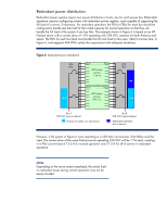
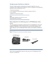
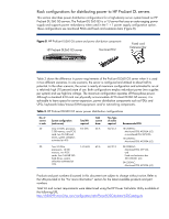
Redundant power distribution Redundant power systems require two power distribution circuits, one for each power bus. Redundant operation requires configuring servers with redundant power supplies, each capable of supporting the full load of a server, if necessary. For redundant operation, the PDU or PDUs for each bus should be configured to handle less than half of their rated capacity for normal operation so that they can handle the full load of the system if one bus fails. The example shown in Figure 6 is based on an HP ProLiant server with a current draw of 1.9A operating with 208 VAC common to North America and Japan. The PDU for each bus feed must handle the full rack load (in this case, 32A) if one bus fails. In Figure 6, multi-segment 40A PDUs satisfy this requirement with adequate headroom. Figure 6. Redundant power distribution 40A PS A PS B PDU HP ProLiant servers 1 thru 8 16 A PS A PS B HP ProLiant servers 9 thru 16 40A PDU 32A 16 A Bus A 208 VAC (see text below) Normal operation (see note below) Bus B 208 VAC (see text below) Redundant operation (Bus A failure) However, if the system in Figure 6 were operating in a 230 VAC environment, 32A PDUs could be used. The current draw of the same ProLiant server operating 230 VAC will be 1.7A each, resulting in a PDU current load of 13.6 A for normal operation and 27.3 A for all16 servers in redundant operation. NOTE: Depending on the server system employed, the actual load on redundant buses during normal operation may not be evenly divided. 8
-
 1
1 -
2
-
 3
3 -
 4
4 -
 5
5 -
 6
6 -
 7
7 -
 8
8 -
 9
9 -
 10
10 -
 11
11 -
 12
12 -
 13
13
 |
 |
