HP Designjet H45000 HP Designjet H35000 and H45000 Printer Series - Unpacking - Page 1
HP Designjet H45000 - Commercial Printer Manual
 |
View all HP Designjet H45000 manuals
Add to My Manuals
Save this manual to your list of manuals |
Page 1 highlights
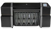
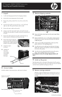
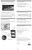
HP Designjet 35000/45000 Printer series Unpacking and Assembly Instructions 1 Unpack 1. Cut the steel shipping bands from the shipping container. 2. Remove the lid and shipping box from the pallet. 3. Remove the packing material from around the outside of the printer. 4. Locate the inks and the accessory kit box, on the shelf at the right rear side of the printer. Remove and set aside. 5. Remove the starter media and set aside. 6. Using a ½-inch (13 mm) socket wrench, remove the four bolts that attach the end plate to the pallet. Remove the end plate and set aside. 7. Remove the pallet ramps from the pallet, and attach them as shown using two of the bolts from the previous step. 8. Remove the bolts that attach the 16 mm printer to the pallet, and the bolts that attach the L-shaped shipping brackets to the printer (4 places). 13 mm 9. Unlock the casters (4 places). 10. Carefully roll the printer on its casters off the pallet and down the ramps. Bolt here Bolt here 2 Connect cables Locate the cables in the accessory box, and connect as shown: Auxiliary power (24V DC) (optional, see manual) 3 Remove shipping restraints Remove the bright colored tape from the media edge holders (on the platen). Reach inside the left cover to cut the plastic restraining band from the service station, and remove the band with attached cardboard spacer. Cut the zip ties holding the light blocker at the front of the platen, and lower it into operating position. Cut and remove zip ties and tape from the input and output tables (rear and front of the printer), and from the adjustable fence (rear of the printer). Cut and remove the shipping band that secures the service station, and completely remove it from the printer. Do not attempt to remove the carriage shipping restraints until Step 5. 4 Switch on the power Press the power switch on the back of the printer to the On position. The printer control panel will walk you through removing the shipping restraints from the printhead carriage (see Step 5). 5 Remove carriage restraints Ê With the included L-shaped hex key, loosen the four screws on the left and right arms, and pull the arms straight out from the carriage. Ê Power On/Standby switch To optional foot switch VideoNet to RIP To power (220V AC) Ì Continued on next page
-
 1
1 -
 2
2
 |
 |