HP Dv5-1125nr HP Pavilion dv5 Entertainment PC - Maintenance and Service Guide - Page 95
Modem module, Display assembly see
 |
View all HP Dv5-1125nr manuals
Add to My Manuals
Save this manual to your list of manuals |
Page 95 highlights
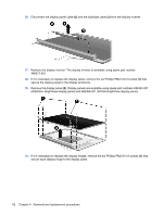
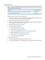
Modem module NOTE: The modem module spare part kits do not include a modem module cable. The modem module cable is included in the Cable Kit, spare part number 501891-001. See Cable Kit on page 31 for more Cable Kit spare part number information. Description Modem module for use in all countries and regions except Australia and New Zealand For use only in Australia and New Zealand Spare part number 461749-001 461749-011 Before removing the modem module, follow these steps: 1. Shut down the computer. If you are unsure whether the computer is off or in Hibernation, turn the computer on, and then shut it down through the operating system. 2. Disconnect all external devices connected to the computer. 3. Disconnect the power from the computer by first unplugging the power cord from the AC outlet and then unplugging the AC Adapter from the computer. 4. Remove the battery (see Battery on page 52). 5. Remove the following components: a. Hard drive (see Hard drive on page 62). b. Optical drive (see Optical drive on page 55). c. Switch cover and keyboard (see Switch cover and keyboard on page 69). d. Speaker assembly (see Speaker assembly on page 74). e. Display assembly (see Display assembly on page 76). f. Top cover (see Top cover on page 84). Remove the modem module: 1. Disconnect the modem module cable (1) from the modem module. 2. Remove the two Phillips PM2.0×4.0 screws (2) that secure the modem module to the system board. Component replacement procedures 87
-
 1
1 -
2
-
3
-
4
-
5
-
6
-
7
-
8
-
9
-
10
-
11
-
12
-
13
-
14
-
15
-
16
-
17
-
18
-
19
-
20
-
21
-
22
-
23
-
24
-
25
-
26
-
27
-
28
-
29
-
30
-
31
-
32
-
33
-
34
-
35
-
36
-
37
-
38
-
39
-
40
-
41
-
42
-
43
-
44
-
45
-
46
-
47
-
48
-
49
-
50
-
51
-
52
-
53
-
54
-
55
-
56
-
57
-
58
-
59
-
60
-
61
-
62
-
63
-
64
-
65
-
66
-
67
-
68
-
69
-
70
-
71
-
72
-
73
-
74
-
75
-
76
-
77
-
78
-
79
-
80
-
81
-
82
-
83
-
84
-
85
-
86
-
87
-
88
-
89
-
 90
90 -
 91
91 -
 92
92 -
 93
93 -
 94
94 -
 95
95 -
 96
96 -
 97
97 -
 98
98 -
 99
99 -
 100
100 -
101
-
102
-
103
-
104
-
105
-
106
-
107
-
108
-
109
-
110
-
111
-
112
-
113
-
114
-
115
-
116
-
117
-
118
-
119
-
120
-
121
-
122
-
123
-
124
-
125
-
126
-
127
-
128
-
129
-
130
-
131
-
132
-
133
-
134
-
135
-
136
-
137
-
138
-
139
-
140
-
141
-
142
-
143
-
144
-
145
-
146
-
147
-
148
-
149
-
150
-
151
-
152
-
153
-
154
-
155
-
156
-
157
-
158
-
159
-
160
-
161
-
162
-
163
-
164
-
165
-
166
-
167
-
168
-
169
-
170
-
171
-
172
-
173
 |
 |
