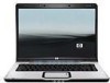
HP Dv6215us HP Pavilion dv6000 Notebook PC Maintenance and Service Guide
HP Dv6215us - Pavilion Entertainment - Turion 64 2 GHz Manual
 |
UPC - 882780963665
View all HP Dv6215us manuals
Add to My Manuals
Save this manual to your list of manuals |
HP Dv6215us manual content summary:
- HP Dv6215us | HP Pavilion dv6000 Notebook PC Maintenance and Service Guide - Page 1
HP Pavilion dv6000 Notebook PC Document Part Number: 416618-003 April 2007 This guide is a troubleshooting reference used for maintaining and servicing the computer. It provides comprehensive information on identifying computer features, components, and spare parts; troubleshooting computer problems - HP Dv6215us | HP Pavilion dv6000 Notebook PC Maintenance and Service Guide - Page 2
Development Company, L.P. Microsoft, Windows and Windows Vista are either trademarks HP shall not be liable for technical or editorial errors or omissions contained herein. Maintenance and Service Guide HP Pavilion dv6000 Notebook PC Third Edition: April 2007 First Edition: August 2006 Document Part - HP Dv6215us | HP Pavilion dv6000 Notebook PC Maintenance and Service Guide - Page 3
on your lap or obstruct the computer air vents. Use the computer only on a hard, flat surface. Do not allow another hard surface, such as an adjoining optional printer, or a soft surface, such as pillows or rugs or clothing, to block airflow. Also, do not allow the AC adapter to contact the skin or - HP Dv6215us | HP Pavilion dv6000 Notebook PC Maintenance and Service Guide - Page 4
1.5 Design overview 1-21 2 Troubleshooting 2.1 Setup Utility in Windows XP 2-1 Using the Setup Utility 2-1 Setup Utility Menus 2-5 2.2 Setup Utility in Windows Vista 2-8 Using the Setup Utility 2-8 Setup Utility Menus 2-11 2.3 Troubleshooting Flowcharts 2-15 Maintenance and Service Guide v - HP Dv6215us | HP Pavilion dv6000 Notebook PC Maintenance and Service Guide - Page 5
4-2 Plastic Parts 4-2 Cables and Connectors 4-2 4.3 Preventing Damage to Removable Drives 4-3 4.4 Preventing Electrostatic Damage 4-4 4.5 Packaging and Transporting Precautions 4-5 4.6 Workstation Precautions 4-6 4.7 Grounding Equipment and Methods 4-7 vi Maintenance and Service Guide - HP Dv6215us | HP Pavilion dv6000 Notebook PC Maintenance and Service Guide - Page 6
5-3 5.3 Preparing the Computer For Disassembly 5-5 5.4 Hard Drive 5-7 5.5 Computer Feet 5-11 5.6 Memory Module 5-12 5.7 RTC Battery 5-15 5.8 Mini Card Module 5-16 5.9 Optical Drive 5-21 5.10 Switch Cover 5-23 5.11 Keyboard 5-26 5.12 Speaker Assembly 5-30 5.13 Power Button Board 5-31 - HP Dv6215us | HP Pavilion dv6000 Notebook PC Maintenance and Service Guide - Page 7
Contents 6 Specifications A Screw Listing B Backup and Recovery in Windows XP C Backup and Recovery in Windows Vista D Display Component Recycling E Connector Pin Assignments F Power Cord Set Requirements Index viii Maintenance and Service Guide - HP Dv6215us | HP Pavilion dv6000 Notebook PC Maintenance and Service Guide - Page 8
1 Product Description The HP Pavilion dv6000 Notebook PC offers advanced modularity, Intel® Core™ Duo and Celeron® and AMD Turion™ 64 Mobile Technology and Mobile AMD Sempron™ processors, and extensive multimedia support. HP Pavilion dv6000 Notebook PC Maintenance and Service Guide 1-1 - HP Dv6215us | HP Pavilion dv6000 Notebook PC Maintenance and Service Guide - Page 9
15.4-inch WXGA (1280 × 768) TFT display with over 16.7 million colors, varying by computer model ■ 200-, 160-, 120-, 100-, 80-, 60-, or 40-GB high-capacity hard drive, varying by computer model ■ 256-MB DDR synchronous DRAM (SDRAM) at 667 MHz, expandable to 2.0 GB 1-2 Maintenance and Service Guide - HP Dv6215us | HP Pavilion dv6000 Notebook PC Maintenance and Service Guide - Page 10
® Windows Vista™ Business, Windows Vista Home Basic, and Windows® XP Professional ■ Full-size Windows keyboard wireless support for Mini Card IEEE 802.11b and 802.11b/g WLAN device ■ Support for ExpressCard ■ External 90- or 65-watt AC adapter with 3-wire power cord ■ 6-cell or 12-cell Li-Ion battery - HP Dv6215us | HP Pavilion dv6000 Notebook PC Maintenance and Service Guide - Page 11
information). 3. Wait approximately 5 minutes. 4. Replace the RTC battery and reassemble the computer. 5. Connect AC power to the computer. Do not reinsert any batteries at this time. 6. Turn on the computer. All passwords and all CMOS settings have been cleared. 1-4 Maintenance and Service Guide - HP Dv6215us | HP Pavilion dv6000 Notebook PC Maintenance and Service Guide - Page 12
Product Description 1.3 Power Management The computer comes with power management features that extend battery operating time and conserve power. The computer supports the following power management features: ■ Standby ■ Hibernation ■ Setting customization by the user ■ Hotkeys for setting the level - HP Dv6215us | HP Pavilion dv6000 Notebook PC Maintenance and Service Guide - Page 13
computer is plugged into an external power source, the light is turned off when all batteries in the computer are fully charged. If the computer is not plugged into an external power source, the light stays off until the battery reaches a low-battery condition. 1-6 Maintenance and Service Guide - HP Dv6215us | HP Pavilion dv6000 Notebook PC Maintenance and Service Guide - Page 14
light Blinking: The hard drive or optical drive is being accessed. Wireless switch Turns the wireless feature on or off, but does not create a wireless connection. ✎ A wireless network must be set up to establish a wireless connection. Wireless light Blue: An integrated wireless device, such as - HP Dv6215us | HP Pavilion dv6000 Notebook PC Maintenance and Service Guide - Page 15
not prevent the computer from being mishandled or stolen. S-Video-out jack Connects an optional S-Video device such as a television, VCR, camcorder, overhead projector, or video capture card. External monitor port Connects an external VGA monitor or projector. 1-8 Maintenance and Service Guide - HP Dv6215us | HP Pavilion dv6000 Notebook PC Maintenance and Service Guide - Page 16
On select computer models, the Supports the following optional digital card formats: Secure Digital (SD) Memory Card, MultiMediaCard (MMC), Secure Digital Input/Output (SD I/O), Memory Stick (MS), Memory Stick Pro (MSP), xDPicture Card (XD), xD-Picture Card (XD) Type M. Maintenance and Service Guide - HP Dv6215us | HP Pavilion dv6000 Notebook PC Maintenance and Service Guide - Page 17
3 4 Table 1-3 Right-Side Components Component Function ExpressCard slot Supports optional ExpressCard/54 cards. Optical drive Reads an optical disc. USB port (select models only) Connects an optional USB device. Power connector Connects an AC adapter. 1-10 Maintenance and Service Guide - HP Dv6215us | HP Pavilion dv6000 Notebook PC Maintenance and Service Guide - Page 18
Product Description The computer keyboard components are shown below and described in Table 1-4. Keyboard Components Maintenance and Service Guide 1-11 - HP Dv6215us | HP Pavilion dv6000 Notebook PC Maintenance and Service Guide - Page 19
when pressed in combination with a function key or the esc key. Windows logo key Displays the Microsoft Windows Start menu. Windows applications key Displays a shortcut menu for items beneath the pointer. numeric keypad, and turns on the num lock light. 1-12 Maintenance and Service Guide - HP Dv6215us | HP Pavilion dv6000 Notebook PC Maintenance and Service Guide - Page 20
Product Description The computer top components are shown below and described in Table 1-5. Top Components, Part 1 Maintenance and Service Guide 1-13 - HP Dv6215us | HP Pavilion dv6000 Notebook PC Maintenance and Service Guide - Page 21
exit hibernation. If the computer has stopped responding and Microsoft® Windows® shutdown procedures cannot be used, press and hold the power button for at least 5 seconds to turn off the computer. Caps lock light On: or the embedded numeric keypad is enabled. 1-14 Maintenance and Service Guide - HP Dv6215us | HP Pavilion dv6000 Notebook PC Maintenance and Service Guide - Page 22
Product Description The computer top components are shown below and described in Table 1-6. Top Components, Part 2 Maintenance and Service Guide 1-15 - HP Dv6215us | HP Pavilion dv6000 Notebook PC Maintenance and Service Guide - Page 23
to start a DVD in the optical drive. If the QuickPlay software is not installed, the DVD button starts in Windows. ✎ In hibernation, opens QuickPlay to start a DVD in the optical drive. If QuickPlay is not installed, the computer resumes from hibernation. 1-16 Maintenance and Service Guide - HP Dv6215us | HP Pavilion dv6000 Notebook PC Maintenance and Service Guide - Page 24
Next/fast forward button When a disc is playing in the optical drive: ■ Play the next track or chapter, when pressed once. ■ Fast forwards when pressed with the fn key. Stop button When a disc is playing in the optical drive, stops the current disc activity. Maintenance and Service Guide 1-17 - HP Dv6215us | HP Pavilion dv6000 Notebook PC Maintenance and Service Guide - Page 25
Product Description The computer TouchPad components are shown below and described in Table 1-7. TouchPad Components Item 1 2 3 4 5 Table 1-7 Touchpad Components Component Enables/disables the TouchPad. TouchPad vertical scroll zone Scrolls up or down. 1-18 Maintenance and Service Guide - HP Dv6215us | HP Pavilion dv6000 Notebook PC Maintenance and Service Guide - Page 26
computer are shown below and described in Table 1-8. Bottom Components Item 1 2 3 Table 1-8 Bottom Components Component Function Battery bay Holds the battery. Battery release latch Releases the battery from the battery bay. Optical drive Reads an optical disc. Maintenance and Service - HP Dv6215us | HP Pavilion dv6000 Notebook PC Maintenance and Service Guide - Page 27
Card slot, and the RTC battery. Vents (5) Enable airflow to cool internal components. ✎ The computer fan starts up automatically to cool internal components and prevent overheating. It is normal for the internal fan to cycle on and off during routine operation. Hard drive bay Holds the hard - HP Dv6215us | HP Pavilion dv6000 Notebook PC Maintenance and Service Guide - Page 28
AMD Turion and Mobile AMD Sempron processors ■ Audio ■ Display ■ ExpressCard ■ Fan ■ Hard drive ■ Intel Core Duo and Celeron processors ■ Keyboard and TouchPad ■ Memory module ■ Mini Card module Ä CAUTION: To properly ventilate the computer, allow at least a 7.6-cm (3-inch) clearance on the left and - HP Dv6215us | HP Pavilion dv6000 Notebook PC Maintenance and Service Guide - Page 29
authorized technicians trained by HP should repair this equipment. All troubleshooting and repair procedures are detailed to allow only subassembly-/module-level repair. Because of the complexity of the individual boards and subassemblies, do not attempt to make repairs at the component level or - HP Dv6215us | HP Pavilion dv6000 Notebook PC Maintenance and Service Guide - Page 30
instructions on the screen. Your preferences go into effect when the computer restarts in Windows. Navigating and Selecting in the Setup Utility Because the Setup Utility is not Windows-based, it does not support 1. If the Setup Utility is open, begin at step 2. 2-2 Maintenance and Service Guide - HP Dv6215us | HP Pavilion dv6000 Notebook PC Maintenance and Service Guide - Page 31
the instructions on the screen. The Setup Utility default settings are set when you exit the Setup Utility and go into effect when the computer restarts. ✎ Your password, security, and language settings are not changed when you restore the factory default settings. Maintenance and Service Guide - HP Dv6215us | HP Pavilion dv6000 Notebook PC Maintenance and Service Guide - Page 32
recommended for advanced users only, refer to the Help and Support Center, which is accessible only when the computer is in Windows. The Setup Utility features available for advanced users include a hard drive self-test, a Network Service Boot, and settings for boot order preferences. The " to - HP Dv6215us | HP Pavilion dv6000 Notebook PC Maintenance and Service Guide - Page 33
Table 2-1 Main Menu To Do This ■ View and change the system time and date. ■ View identification information about the computer. ■ View specification information about the processor, memory size, system BIOS, and keyboard controller version (select models only). Maintenance and Service Guide 2-5 - HP Dv6215us | HP Pavilion dv6000 Notebook PC Maintenance and Service Guide - Page 34
WLAN Device Enable/disable an embedded wireless LAN Radio device. Embedded Bluetooth Enable/disable an embedded Bluetooth device Device (select models only) (select models only). Enhanced SATA support (select models only) Enable/disable enhanced SATA mode. 2-6 Maintenance and Service Guide - HP Dv6215us | HP Pavilion dv6000 Notebook PC Maintenance and Service Guide - Page 35
the boot order for: ❐ USB Floppy ❐ ATAPI CD/DVD ROM Drive ❐ Hard drive ❐ USB Diskette on Key ❐ USB Hard drive ❐ Network adapter Diagnostics Menu Select Hard Disk Self Test Table 2-4 Diagnostics Menu To Do This Run a comprehensive self-test on the hard drive. Maintenance and Service Guide 2-7 - HP Dv6215us | HP Pavilion dv6000 Notebook PC Maintenance and Service Guide - Page 36
Troubleshooting 2.2 Setup Utility in Windows Vista The Setup Utility is a ROM-based information and customization utility that can be used even when your Windows the Setup Utility: 1. Turn on or restart the computer. 2. Before Windows opens and while "Press to enter setup" and Service Guide - HP Dv6215us | HP Pavilion dv6000 Notebook PC Maintenance and Service Guide - Page 37
Troubleshooting 5. To set your preferences and exit the Setup Utility, press f10 and then follow the instructions on the screen. Your preferences go into effect when the computer restarts in Windows. Navigating and Selecting in the Setup Utility Because the Setup Utility is not Windows-based, it - HP Dv6215us | HP Pavilion dv6000 Notebook PC Maintenance and Service Guide - Page 38
features recommended for advanced users only, refer to Help and Support, which is accessible only when the computer is in Windows. The Setup Utility features available for advanced users include a hard drive self-test, a Network Service Boot, and settings for boot order preferences. The " to - HP Dv6215us | HP Pavilion dv6000 Notebook PC Maintenance and Service Guide - Page 39
the Setup Utility closes, the computer restarts in Windows. Setup Utility Menus The menu tables in this section provide an overview of Setup Utility options. ✎ Some of the Setup Utility menu items listed in this chapter may not be supported by your computer. Maintenance and Service Guide 2-11 - HP Dv6215us | HP Pavilion dv6000 Notebook PC Maintenance and Service Guide - Page 40
Troubleshooting Main Menu Select System Information Table 2-1 Main Menu To Do This ■ View and change the system time and date. ■ View identification information about the computer. ■ View specification information about the processor, memory size, system BIOS, and keyboard controller version ( - HP Dv6215us | HP Pavilion dv6000 Notebook PC Maintenance and Service Guide - Page 41
Internal Network Adapter. ■ Boot Order-Set the boot order for: ❐ USB Floppy ❐ ATAPI CD/DVD ROM Drive ❐ Hard drive ❐ USB Diskette on Key ❐ USB Hard drive ❐ Network adapter Enable/disable the Quick Launch Button tapping sound. Select the amount of video memory. Maintenance and Service Guide 2-13 - HP Dv6215us | HP Pavilion dv6000 Notebook PC Maintenance and Service Guide - Page 42
To Do This Run a comprehensive self-test on the hard drive. Secondary Hard Disk Self Test (select models only) ✎ On models with two hard drives, this menu option is called the Primary Hard Disk Self Test. Run a comprehensive self-test on a secondary hard drive. 2-14 Maintenance and Service Guide - HP Dv6215us | HP Pavilion dv6000 Notebook PC Maintenance and Service Guide - Page 43
No Operating System (OS) Loading" 2.10 "Flowchart 2.10-No OS Loading, Hard Drive, Part 1" 2.11 "Flowchart 2.11-No OS Loading, Hard Drive, Part 2" 2.12 "Flowchart 2.12-No OS Loading, Hard Drive, Part 3" 2.13 "Flowchart 2.13-No OS Loading, Diskette Drive" Maintenance and Service Guide 2-15 - HP Dv6215us | HP Pavilion dv6000 Notebook PC Maintenance and Service Guide - Page 44
Troubleshooting Table 2-5 Troubleshooting Flowcharts Overview (Continued) Flowchart Description 2.14 "Flowchart 2.14-No OS Loading, Optical Drive" 2.15 "Flowchart 2.15-No Audio, Part 1" 2.16 "Flowchart 2.16-No Audio, Part 2" 2.17 "Flowchart 2.17-Nonfunctioning Device" 2.18 "Flowchart 2. - HP Dv6215us | HP Pavilion dv6000 Notebook PC Maintenance and Service Guide - Page 45
Initial Troubleshooting Begin troubleshooting. N Is there power? Y Go to "Flowchart 2.2-No Power, Part 1." N Beeps, LEDs, or error messages? Y N Is there video? (no boot) Y N Is the OS loading? Y N Is there sound? Y Check LED board, speaker connections. Y Go to "Flowchart 2.6-No Video, Part - HP Dv6215us | HP Pavilion dv6000 Notebook PC Maintenance and Service Guide - Page 46
Troubleshooting Flowchart 2.2-No Power, Part 1 No power (power LED is off). Remove from docking device (if applicable). N Power up on battery power? Y Reset power.* N Power up on battery power? Y Go to "Flowchart 2.3-No Power, Part 2." N Power up on AC power? Y Reset power.* N Power up on - HP Dv6215us | HP Pavilion dv6000 Notebook PC Maintenance and Service Guide - Page 47
in battery socket and clean if necessary. Y Power on? Done N Check battery by recharging it, moving it to another computer, or replacing it. N Power on? Y Replace power supply (if applicable). N Done Power on? Y Go to "Flowchart 2.4-No Power, Part 3." Done Maintenance and Service Guide - HP Dv6215us | HP Pavilion dv6000 Notebook PC Maintenance and Service Guide - Page 48
Troubleshooting Flowchart 2.4-No Power, Part 3 Continued from "Flowchart 2.3-No Power, Part 2." Plug directly into AC outlet. Y Power LED on? N Reseat AC adapter in computer and at power source. Y Power on? N N Power outlet active? Y Replace power cord. Y Power on? N Done Done Try different - HP Dv6215us | HP Pavilion dv6000 Notebook PC Maintenance and Service Guide - Page 49
computer. Y Loose or damaged parts? N Reseat loose components and boards and replace damaged items. Close computer and retest. N Power on? Y Done Replace the following items (if applicable). Check computer operation after each replacement: 1. Internal DC-DC converter* 2. Internal AC adapter - HP Dv6215us | HP Pavilion dv6000 Notebook PC Maintenance and Service Guide - Page 50
Troubleshooting Flowchart 2.6-No Video, Part 1 No video. Docking Device Stand-alone or docking device? Go to "Flowchart 2.7-No Video, Part following one at a time. Test after each replacement. 1. Cable between computer and computer display (if applicable) 2. Display 3. System board N Video OK? Y - HP Dv6215us | HP Pavilion dv6000 Notebook PC Maintenance and Service Guide - Page 51
Troubleshooting Flowchart 2.7-No Video, Part 2 Continued from "Flowchart 2.6-No Video, Part 1." Remove computer from docking device, if connected. Adjust display brightness. Check brightness of external monitor. N Y Go to "A" in Video OK? "Flowchart Video OK? Done 2.6-No Video, Part 1." - HP Dv6215us | HP Pavilion dv6000 Notebook PC Maintenance and Service Guide - Page 52
Troubleshooting Flowchart 2.8-Nonfunctioning Docking Device (if applicable) Nonfunctioning docking device. Reseat power cord in docking device and power outlet. Check voltage setting on docking device. Reinstall computer into docking device. Reset monitor cable connector at docking device. Y - HP Dv6215us | HP Pavilion dv6000 Notebook PC Maintenance and Service Guide - Page 53
Troubleshooting Flowchart 2.9-No Operating System (OS) Loading No OS loading.* Reseat power cord in docking device and power outlet. No OS loading from hard drive, go to "Flowchart 2.10-No OS Loading, Hard Drive, Part 1." No OS loading from diskette drive, go to "Flowchart 2.13-No OS Loading, - HP Dv6215us | HP Pavilion dv6000 Notebook PC Maintenance and Service Guide - Page 54
2.11-No OS Loading, Hard Drive, Part 2." Done N Boot from diskette? Y Change boot priority through the Setup Utility and reboot. N Boot from hard drive? Y Go to "Flowchart 2.13-No OS Loading, Diskette Drive." Go to "Flowchart 2.17-Nonfunctioning Device." 2-26 Maintenance and Service Guide - HP Dv6215us | HP Pavilion dv6000 Notebook PC Maintenance and Service Guide - Page 55
? Y Create partition, and then format hard drive to bootable C:\ prompt. Format hard drive and bring to a bootable C:\ prompt. Y Computer booted? N Go to "Flowchart 2.12-No OS Loading, Hard Drive, Part 3." Load OS using Operating System disc (if applicable). Maintenance and Service Guide 2-27 - HP Dv6215us | HP Pavilion dv6000 Notebook PC Maintenance and Service Guide - Page 56
Troubleshooting Flowchart 2.12-No OS Loading, Hard Drive, Part 3 Continued from "Flowchart 2.11-No OS Loading, Hard Drive, Part 2." N System files on hard drive? Y Install OS and reboot. Y Virus on hard drive? N Run SCANDISK and check for bad sectors. N Can bad sectors be fixed? Y Clean virus. - HP Dv6215us | HP Pavilion dv6000 Notebook PC Maintenance and Service Guide - Page 57
each replacement: N ■ Diskette drive ■ System board Y Reset the computer. Refer to OS loading? Done Section 1.2, "Resett ing the N Computer," for instructions. Change boot priority using the Setup Utility. Go to "Flowchart 2.17-Nonfunctioning Device." Maintenance and Service Guide 2-29 - HP Dv6215us | HP Pavilion dv6000 Notebook PC Maintenance and Service Guide - Page 58
Y Done Go to "Flowchart 2.17-Nonfunctioning Device." Y Reset the computer. Booting order correct? N Refer to Section 1.2, "Resett ing the Computer," for instructions. Go to "Flowchart 2.17-Nonfunctioning Device." Correct boot order using the Setup Utility. 2-30 Maintenance and Service Guide - HP Dv6215us | HP Pavilion dv6000 Notebook PC Maintenance and Service Guide - Page 59
Troubleshooting Flowchart 2.15-No Audio, Part 1 No audio. Y Turn up audio internally or Audio? Done externally. N Y Computer in docking device (if applicable)? N Undock N Internal audio? Y Go to "Flowchart 2.16-No Audio, Part 2." Go to "Flowchart 2.16-No Audio, Part 2." Replace the - HP Dv6215us | HP Pavilion dv6000 Notebook PC Maintenance and Service Guide - Page 60
Troubleshooting Flowchart 2.16-No Audio, Part 2 Continued from "Flowchart 2.15-No Audio, Part 1." N Audio driver in OS configured? Y Reload audio drivers. N Correct drivers for application? Y Load drivers and set configuration in OS. Connect to external speaker. N Replace audio Y board - HP Dv6215us | HP Pavilion dv6000 Notebook PC Maintenance and Service Guide - Page 61
and plugs for bent or broken pins or other damage. Clear CMOS. Reattach device. Close computer, plug in power, and reboot. N Device boots properly? Y Y Any physical device detected? N Replace hard drive. Replace NIC. If integrated NIC, replace system board. Fix or replace broken item. Go to - HP Dv6215us | HP Pavilion dv6000 Notebook PC Maintenance and Service Guide - Page 62
Troubleshooting Flowchart 2.18-Nonfunctioning Keyboard Keyboard not operating properly. Connect computer to good external keyboard. N External device works? Y Replace system board. cable. Y Keyboard Done operating Done properly? N Replace system board. 2-34 Maintenance and Service Guide - HP Dv6215us | HP Pavilion dv6000 Notebook PC Maintenance and Service Guide - Page 63
Troubleshooting Flowchart 2.19-Nonfunctioning Pointing Device Pointing device not operating properly. Connect computer to good external pointing device. N External device works? . Y Pointing device Done operating Done properly? N Replace system board. Maintenance and Service Guide 2-35 - HP Dv6215us | HP Pavilion dv6000 Notebook PC Maintenance and Service Guide - Page 64
and or modem connection Done in OS? reconfigure. working? Y N Disconnect all power from the computer and open. Reseat NIC/modem (if applicable). Replace NIC/modem (if applicable). Y Network or modem connection Done working? N Replace system board. 2-36 Maintenance and Service Guide - HP Dv6215us | HP Pavilion dv6000 Notebook PC Maintenance and Service Guide - Page 65
an illustrated parts breakdown and a reference for spare part numbers and option part numbers. 3.1 Serial Number Location When ordering parts or requesting information, provide the computer serial number and model number located on the bottom of the computer. Maintenance and Service Guide 3-1 - HP Dv6215us | HP Pavilion dv6000 Notebook PC Maintenance and Service Guide - Page 66
Illustrated Parts Catalog 3.2 Computer Major Components Computer Major Components 3-2 Maintenance and Service Guide - HP Dv6215us | HP Pavilion dv6000 Notebook PC Maintenance and Service Guide - Page 67
Spare Part Number Display assemblies (include wireless antenna transceivers and cables) For use with full-featured computer models with camera (includes camera, camera cable, and microphones) 15.4-inch, WXGA, TFT with BrightView for use only with computer models sold at Best Buy 15.4-inch - HP Dv6215us | HP Pavilion dv6000 Notebook PC Maintenance and Service Guide - Page 68
Illustrated Parts Catalog Computer Major Components 3-4 Maintenance and Service Guide - HP Dv6215us | HP Pavilion dv6000 Notebook PC Maintenance and Service Guide - Page 69
Parts Catalog Table 3-1 Spare Parts: Computer Major Components (Continued) Item 4 5 Description Spare Part Number Keyboards For use with all computer ) For use with full-featured computer models For use with defeatured computer models 431416-001 431418-001 Maintenance and Service Guide 3-5 - HP Dv6215us | HP Pavilion dv6000 Notebook PC Maintenance and Service Guide - Page 70
Illustrated Parts Catalog Computer Major Components 3-6 Maintenance and Service Guide - HP Dv6215us | HP Pavilion dv6000 Notebook PC Maintenance and Service Guide - Page 71
431449-001 431448-001 Plastics Kit 438368-001 Includes: ExpressCard slot bezel Hard drive cover (includes 2 captive screws, secured by C-clips) Memory module compartment cover (includes 2 captive screws, secured by C-clips) ExpressCard assembly 438317-001 Maintenance and Service Guide 3-7 - HP Dv6215us | HP Pavilion dv6000 Notebook PC Maintenance and Service Guide - Page 72
Illustrated Parts Catalog Computer Major Components 3-8 Maintenance and Service Guide - HP Dv6215us | HP Pavilion dv6000 Notebook PC Maintenance and Service Guide - Page 73
Part Number 434730-001 430896-001 434731-001 436900-001 441762-001 430897-001 436157-001 419437-001 441763-001 430898-001 441761-001 436159-001 434735-001 436257-001 431373-001 431372-001 431371-001 434414-001 431375-001 431374-001 434722-001 434723-001 434724-001 Maintenance and Service Guide - HP Dv6215us | HP Pavilion dv6000 Notebook PC Maintenance and Service Guide - Page 74
Illustrated Parts Catalog Computer Major Components 3-10 Maintenance and Service Guide - HP Dv6215us | HP Pavilion dv6000 Notebook PC Maintenance and Service Guide - Page 75
wireless switch) For use with full-featured computer models For use with defeatured computer models 431426-001 432921-001 Rubber Feet Kit (includes computer feet, not illustrated) 431430-001 Batteries 12-cell, 8.8-AHr 6-cell, 4.0-AHr 432307-001 432306-001 Maintenance and Service Guide - HP Dv6215us | HP Pavilion dv6000 Notebook PC Maintenance and Service Guide - Page 76
Illustrated Parts Catalog Computer Major Components 3-12 Maintenance and Service Guide - HP Dv6215us | HP Pavilion dv6000 Notebook PC Maintenance and Service Guide - Page 77
hard drive for use only with computer models using AMD processors 434415-001 Hard Drive Bracket Kit (includes hard drive bracket and 4 screws used to secure the bracket to the hard drive) 436156-001 Mini Card modules 802.11a/b/g WLAN Mini Card States Vietnam Maintenance and Service Guide 3-13 - HP Dv6215us | HP Pavilion dv6000 Notebook PC Maintenance and Service Guide - Page 78
Illustrated Parts Catalog Computer Major Components 3-14 Maintenance and Service Guide - HP Dv6215us | HP Pavilion dv6000 Notebook PC Maintenance and Service Guide - Page 79
Catalog Table 3-1 Spare Parts: Computer Major Components (Continued) Item 19 Description Mini Card modules (Continued) 802.11a/b/g WLAN Mini Card module for use only with computer models using Intel processors in the countries or regions listed below. These countries or regions are categorized - HP Dv6215us | HP Pavilion dv6000 Notebook PC Maintenance and Service Guide - Page 80
Illustrated Parts Catalog Computer Major Components 3-16 Maintenance and Service Guide - HP Dv6215us | HP Pavilion dv6000 Notebook PC Maintenance and Service Guide - Page 81
Parts Catalog Table 3-1 Spare Parts: Computer Major Components (Continued) Item 19 Description Mini Card modules (Continued) 802.11a/b/g WLAN Mini Card module for use only with computer models using Intel processors in Japan 802.11a/b/g WLAN Mini Card module for use only with computer Part - HP Dv6215us | HP Pavilion dv6000 Notebook PC Maintenance and Service Guide - Page 82
Illustrated Parts Catalog Computer Major Components 3-18 Maintenance and Service Guide - HP Dv6215us | HP Pavilion dv6000 Notebook PC Maintenance and Service Guide - Page 83
Parts: Computer Major Components (Continued) Item 19 Description Mini Card modules (Continued) 802.11a/b/g WLAN Mini Card module for use only with computer Korea 802.11b/g WLAN Mini Card module for use with all computer models in the Poland Portugal Romania Spare Part Number 407160-002 Uruguay - HP Dv6215us | HP Pavilion dv6000 Notebook PC Maintenance and Service Guide - Page 84
Illustrated Parts Catalog Computer Major Components 3-20 Maintenance and Service Guide - HP Dv6215us | HP Pavilion dv6000 Notebook PC Maintenance and Service Guide - Page 85
Ecuador Haiti Honduras Pakistan Peru Qatar South Korea Uruguay Venezuela 802.11b/g WLAN Mini Card module for use only with 407159-291 computer models using Intel processors in Japan RTC battery (includes 2-sided tape) 431436-001 Memory modules, PC2-5300, 667-MHz, 1-DIMM For use only with - HP Dv6215us | HP Pavilion dv6000 Notebook PC Maintenance and Service Guide - Page 86
computer models with camera (includes camera and microphone openings) For use with full-featured computer models without camera (includes microphone openings) For use with defeatured computer models Spare Part Number 436260-001 431388-001 433281-001 433282-001 3-22 Maintenance and Service Guide - HP Dv6215us | HP Pavilion dv6000 Notebook PC Maintenance and Service Guide - Page 87
panel with BrightView 15.4-inch, WXGA, SVA display panel AntiGlare Wireless antenna transceivers and cables Microphone Display Cable Kit (includes camera cable) Display enclosures For use only with full-featured computer models sold at Best Buy For use with full-featured computer models For use - HP Dv6215us | HP Pavilion dv6000 Notebook PC Maintenance and Service Guide - Page 88
Illustrated Parts Catalog 3.4 Mass Storage Devices Mass Storage Devices 3-24 Maintenance and Service Guide - HP Dv6215us | HP Pavilion dv6000 Notebook PC Maintenance and Service Guide - Page 89
Catalog Item 1 2 Table 3-3 Mass Storage Devices Spare Part Number Information Description Spare Part Number Hard drives (all 5400-rpm, include bracket and connector) For use with all computer models: 200-GB (4200-rpm) 160-GB (5400-rpm) 120-GB 100-GB 80-GB 60-GB 441424-001 438485-001 431407 - HP Dv6215us | HP Pavilion dv6000 Notebook PC Maintenance and Service Guide - Page 90
Illustrated Parts Catalog 3.5 Plastics Kit Plastics Kit Components 3-26 Maintenance and Service Guide - HP Dv6215us | HP Pavilion dv6000 Notebook PC Maintenance and Service Guide - Page 91
Spare Part Number Information Description Spare Part Number Plastics Kit 438368-001 Includes: ExpressCard slot bezel Hard drive cover (includes 2 captive screws, secured by C-clips) Memory module compartment cover (includes 2 captive screws, secured by C-clips) Maintenance and Service Guide - HP Dv6215us | HP Pavilion dv6000 Notebook PC Maintenance and Service Guide - Page 92
3.6 Miscellaneous Table 3-5 Spare Parts: Miscellaneous Description AC adapters HP 90W PFC AC Adapter HP 90W non-PFC AC Adapter HP 65W AC Adapter DVB-T TV tuner Analog TV tuner Carrying case Composite S-Video and audio input cable Headset Backpack HP Remote Control HP Remote Control Logo Kit Optical - HP Dv6215us | HP Pavilion dv6000 Notebook PC Maintenance and Service Guide - Page 93
Parts: Miscellaneous (Continued) Description Spare Part Number TV tuner antenna 439131-001 Wireless laser mouse 430958-001 USB travel mouse 435836-001 Power cords For use with all computer Hong Kong 394279-031 For use only with computer models using Intel processors in the following - HP Dv6215us | HP Pavilion dv6000 Notebook PC Maintenance and Service Guide - Page 94
Parts: Miscellaneous (Continued) Description Spare Part Number Screw Kits (includes the following screws; refer to Appendix A, "Screw Listing," for more information on screw specifications and usage) For use only with computer screw ■ Phillips PM2.0×3.0 screw 3-30 Maintenance and Service Guide - HP Dv6215us | HP Pavilion dv6000 Notebook PC Maintenance and Service Guide - Page 95
Power cord for use only with computer models using Intel processors in the People's Republic of China Power cord for use in Korea Power cord for use in Israel Power cord for use only with computer models using AMD processors in India HP 65W PFC AC Adapter Backpack Maintenance and Service Guide - HP Dv6215us | HP Pavilion dv6000 Notebook PC Maintenance and Service Guide - Page 96
Romania 802.11b/g WLAN Mini Card module for use in the ROW countries or regions listed below: China Ecuador Haiti Honduras Pakistan Peru Qatar South Korea 802.11b/g WLAN Mini Card module for use only with computer models using Intel processors in Japan 3-32 Maintenance and Service Guide - HP Dv6215us | HP Pavilion dv6000 Notebook PC Maintenance and Service Guide - Page 97
Parts: Sequential Part Number Listing (Continued) Spare Part Number 407160-001 407160-002 Description 802.11a/b/g WLAN Mini Card module for use only with computer Philippines Poland Portugal Romania 802.11a/b/g WLAN Mini Card module for use only with computer models using AMD processors in the - HP Dv6215us | HP Pavilion dv6000 Notebook PC Maintenance and Service Guide - Page 98
Spare Parts: Sequential Part Number Listing (Continued) Spare Part Number 407313-001 407674-001 407674-002 Description HP Remote Control 802.11a/b/g WLAN Mini Card module for use only with computer Sweden Switzerland Turkey The United Kingdom Uzbekistan 3-34 Maintenance and Service Guide - HP Dv6215us | HP Pavilion dv6000 Notebook PC Maintenance and Service Guide - Page 99
. 802.11a/b/g WLAN Mini Card module for use only with computer models using Intel processors in Japan Composite S-Video and audio input cable RF input adapter cable Analog TV tuner processor Intel Core Duo T2050 (1.60-GHz) processor Wireless laser mouse Maintenance and Service Guide 3-35 - HP Dv6215us | HP Pavilion dv6000 Notebook PC Maintenance and Service Guide - Page 100
assembly for use with full-featured computer models with camera (includes camera, camera cable, microphones, and wireless antenna transceivers and cables) 15.4-inch, WXGA, SVA display panel with BrightView for use only with computer models using AMD processors 15.4-inch, WXGA, SVA AntiGlare display - HP Dv6215us | HP Pavilion dv6000 Notebook PC Maintenance and Service Guide - Page 101
667-MHz, 1-DIMM) 1024-MB memory module for use only with computer models using AMD processors (PC-5300, 667-MHz, 1-DIMM) 60-GB hard drive (5400-rpm, includes bracket and connector) 80-GB hard drive (5400-rpm, includes bracket and connector) 100-GB hard drive (5400-rpm, includes bracket and connector - HP Dv6215us | HP Pavilion dv6000 Notebook PC Maintenance and Service Guide - Page 102
Kit RTC battery (includes 2-sided tape) Power button board (includes power button board cable) Audio board for use with full-featured computer models (includes infrared lens) Audio board for use with defeatured computer models (does not include infrared lens) 3-38 Maintenance and Service Guide - HP Dv6215us | HP Pavilion dv6000 Notebook PC Maintenance and Service Guide - Page 103
cables; does not include camera or camera cable) 15.4-inch, WXGA, TFT Antiglare display assembly for use with full-featured computer models without camera (includes microphones and wireless antenna transceivers and cables; does not include camera or camera cable) Maintenance and Service Guide 3-39 - HP Dv6215us | HP Pavilion dv6000 Notebook PC Maintenance and Service Guide - Page 104
-001 434730-001 Description 6-cell, 4.0-AHr battery 12-cell, 8.8-AHr battery HP 90W PFC AC Adapter HP 90W non-PFC AC Adapter Display enclosure for use with defeatured computer models Base enclosure for use with defeatured computer models (includes wireless switch) System board for use only with - HP Dv6215us | HP Pavilion dv6000 Notebook PC Maintenance and Service Guide - Page 105
and cables) 15.4-inch, WXGA, TFT Antiglare display assembly for use only with full-featured computer models using AMD processors with camera sold at Best Buy (includes camera and camera cable, microphones, and wireless antenna transceivers and cables) Maintenance and Service Guide 3-41 - HP Dv6215us | HP Pavilion dv6000 Notebook PC Maintenance and Service Guide - Page 106
Display hinge covers for use only with full-featured computer models using AMD processors with camera sold at Best Buy System board for use only with defeatured computer models using AMD processors in Latin America Hard Drive Bracket Kit Intel Core Duo T5500 (1.66-GHz) processor Intel Core Duo T1350 - HP Dv6215us | HP Pavilion dv6000 Notebook PC Maintenance and Service Guide - Page 107
Spare Parts: Sequential Part Number computer models using Intel processors in Japan Keyboard for use in Belgium Keyboard for use only with computer models using Intel processors in Taiwan Keyboard for use only with computer models using Intel processors in Korea Maintenance and Service Guide - HP Dv6215us | HP Pavilion dv6000 Notebook PC Maintenance and Service Guide - Page 108
only with computer models using AMD processors in Denmark, Finland, Norway, and Sweden Intel Celeron 440 (1.86-GHz) processor, use with dv6200 Intel Core Duo T2350 (1.60-GHz) processor, use with dv6200 Intel Core Duo T2060 (1.60-GHz) processor, use with dv6200 3-44 Maintenance and Service Guide - HP Dv6215us | HP Pavilion dv6000 Notebook PC Maintenance and Service Guide - Page 109
4 Removal and Replacement Preliminaries This chapter provides essential information for proper and safe removal and replacement service. 4.1 Tools Required You will need the following tools to complete the removal and replacement procedures: ■ Magnetic screwdriver ■ Phillips P0 and P1 screwdrivers ■ - HP Dv6215us | HP Pavilion dv6000 Notebook PC Maintenance and Service Guide - Page 110
parts. Use care when handling the plastic parts. Apply pressure only at the points designated in the maintenance instructions. Cables and Connectors Ä CAUTION: When servicing the computer cannot be caught or snagged by parts being removed or replaced. Handle flex cables with extreme care; - HP Dv6215us | HP Pavilion dv6000 Notebook PC Maintenance and Service Guide - Page 111
, or loss of information, observe the following precautions: ■ Before removing or inserting a hard drive, shut down the computer. If you are unsure whether the computer is off or in hibernation, turn the computer on, and then shut it down through the operating system. ■ Before removing a diskette - HP Dv6215us | HP Pavilion dv6000 Notebook PC Maintenance and Service Guide - Page 112
many integrated circuits provide some protection, but in many cases, the discharge contains enough power to alter device parameters or melt silicon junctions. A sudden discharge of static electricity degrade in the internal layers, reducing its life expectancy. 4-4 Maintenance and Service Guide - HP Dv6215us | HP Pavilion dv6000 Notebook PC Maintenance and Service Guide - Page 113
grounded when touching a sensitive component or assembly. ■ Store reusable electrostatic-sensitive parts from assemblies in protective packaging or nonconductive foam. ■ Use transporters and conveyors not possible, use an ionizer to dissipate electric charges. Maintenance and Service Guide 4-5 - HP Dv6215us | HP Pavilion dv6000 Notebook PC Maintenance and Service Guide - Page 114
components, parts, and assemblies by the case or PCM laminate. Handle these items only at static-free workstations. ■ Avoid contact with pins, leads, or circuitry. ■ Turn off power and input signals before inserting or removing connectors or test equipment. 4-6 Maintenance and Service Guide - HP Dv6215us | HP Pavilion dv6000 Notebook PC Maintenance and Service Guide - Page 115
tables or floor mats with hard ties to the ground. ■ Field service kits. ■ Static awareness labels. ■ Material-handling packages. ■ Nonconductive plastic bags, tubes, or boxes. ■ Metal tote boxes. ■ Electrostatic voltage levels and protective materials. Maintenance and Service Guide 4-7 - HP Dv6215us | HP Pavilion dv6000 Notebook PC Maintenance and Service Guide - Page 116
4-1 Typical Electrostatic Voltage Levels Relative Humidity Event 10% 40% 55% Walking across carpet 35,000 V 15,000 V 7,500 V Walking across vinyl floor 12,000 V 5,000 V 3,000 V Motions of Floor mats 7,500 V Metallized laminate Floor mats 5,000 V 4-8 Maintenance and Service Guide - HP Dv6215us | HP Pavilion dv6000 Notebook PC Maintenance and Service Guide - Page 117
and replacement procedures. There are as many as 81 screws, in 8 different sizes, that must be removed, replaced, or loosened when servicing the computer. Make special note of each screw size and location during removal and replacement. Refer to Appendix A, "Screw Listing," for detailed information - HP Dv6215us | HP Pavilion dv6000 Notebook PC Maintenance and Service Guide - Page 118
Removal and Replacement Procedures 5.1 Serial Number Report the computer serial number to HP when requesting information or ordering spare parts. The serial number is located on the bottom of the computer. Serial Number Location 5-2 Maintenance and Service Guide - HP Dv6215us | HP Pavilion dv6000 Notebook PC Maintenance and Service Guide - Page 119
Removed Preparing the Computer For Disassembly Battery 0 Hard Drive 2 loosened to remove the hard drive cover 6 removed to disassemble the hard drive Computer Feet 0 Memory Module 2 loosened to remove the memory module compartment cover RTC Battery 0 Mini Card Module 2 Ä To prevent - HP Dv6215us | HP Pavilion dv6000 Notebook PC Maintenance and Service Guide - Page 120
Top Cover Audio Board Bluetooth Module ExpressCard Assembly USB/Power Connector Board System Board Fan/Heat Sink Assembly Processor # of Screws Removed 2 2 4 6 0 0 4 4 2 0 0 14 to remove the top cover 4 to remove the top cover support trim 2 2 4 2 2 4 1 loosened 5-4 Maintenance and Service Guide - HP Dv6215us | HP Pavilion dv6000 Notebook PC Maintenance and Service Guide - Page 121
to the computer. 3. Disconnect the power cord. Battery Spare Part Number Information 12-cell, 8.8-AHr 6-cell, 4.0-AHr 432307-001 432306-001 4. Remove the battery by following these steps: a. Turn the computer upside down with the front panel toward you. Maintenance and Service Guide 5-5 - HP Dv6215us | HP Pavilion dv6000 Notebook PC Maintenance and Service Guide - Page 122
hold the battery release latch 1 to the left. (The front edge of the battery disengages from the computer.) c. Lift the front edge of the battery 2 and swing it back. d. Remove the battery. Removing the Battery Reverse the above procedure to install the battery. 5-6 Maintenance and Service Guide - HP Dv6215us | HP Pavilion dv6000 Notebook PC Maintenance and Service Guide - Page 123
Bracket Kit (includes hard drive bracket and 4 screws used to secure the bracket to the hard drive) 441424-001 438485-001 431407-001 431406-001 431405-001 431404-001 434743-001 434415-001 436156-001 1. Prepare the computer for disassembly (refer to Section 5.3). Maintenance and Service Guide 5-7 - HP Dv6215us | HP Pavilion dv6000 Notebook PC Maintenance and Service Guide - Page 124
1 that secure the hard drive cover to the computer. 3. Lift the right side of the cover 2 and swing it to the left. 4. Remove the hard drive cover. ✎ The hard drive cover is included in the Plastics Kit, spare part number 438368-001. Removing the Hard Drive Cover 5-8 Maintenance and Service Guide - HP Dv6215us | HP Pavilion dv6000 Notebook PC Maintenance and Service Guide - Page 125
Removal and Replacement Procedures 5. Use the mylar tab 1 to lift the hard drive 2 until it disconnects from the computer. 6. Remove the hard drive from the hard drive bay. Removing the Hard Drive Maintenance and Service Guide 5-9 - HP Dv6215us | HP Pavilion dv6000 Notebook PC Maintenance and Service Guide - Page 126
the six Phillips PM3.0×3.0 screws 1 that secure the hard drive bracket to the hard drive. 8. Lift the bracket 2 straight up to remove if from the hard drive. Removing the Hard Drive Bracket Reverse the above procedure to install and reassemble the hard drive. 5-10 Maintenance and Service Guide - HP Dv6215us | HP Pavilion dv6000 Notebook PC Maintenance and Service Guide - Page 127
Procedures 5.5 Computer Feet The computer feet are adhesive-backed rubber pads. The feet are included in the Rubber Feet Kit, spare part number 431430-001. The feet attach to the base enclosure in the locations illustrated below. Computer Feet Locations Maintenance and Service Guide 5-11 - HP Dv6215us | HP Pavilion dv6000 Notebook PC Maintenance and Service Guide - Page 128
Removal and Replacement Procedures 5.6 Memory Module Memory Module Spare Part Number Information For use only with computer models using Intel processors: 1024-MB 512-MB 256-MB For use only with computer models using AMD processors: 1024-MB 512-MB 256-MB 434742-001 434741-001 434740-001 431403- - HP Dv6215us | HP Pavilion dv6000 Notebook PC Maintenance and Service Guide - Page 129
memory module compartment cover 2, and then swing it to the right. 4. Remove the memory module compartment cover. ✎ The memory module compartment cover is included in the Plastics Kit, spare part number 431428-001. Removing the Memory Module Compartment Cover Maintenance and Service Guide 5-13 - HP Dv6215us | HP Pavilion dv6000 Notebook PC Maintenance and Service Guide - Page 130
the computer.) 6. Slide the module 2 away from the socket at an angle. ✎ Memory modules are designed with a notch 3 to prevent incorrect installation into the memory module socket. Removing a Memory Module Reverse the above procedure to install a memory module. 5-14 Maintenance and Service Guide - HP Dv6215us | HP Pavilion dv6000 Notebook PC Maintenance and Service Guide - Page 131
1 from the system board. 4. Remove the RTC battery 2. ✎ The RTC battery is secured to the computer by 2-sided tape. All replacement RTC battery spare part kits include 2-sided tape. Removing the RTC Battery Reverse the above procedure to install the RTC battery. Maintenance and Service Guide 5-15 - HP Dv6215us | HP Pavilion dv6000 Notebook PC Maintenance and Service Guide - Page 132
and Replacement Procedures 5.8 Mini Card Module Mini Card Module Spare Part Number Information 802.11a/b/g WLAN Mini Card module for use only with computer models using Intel processors in the Lanka Sweden Switzerland Turkey The United Kingdom Uzbekistan 5-16 Maintenance and Service Guide - HP Dv6215us | HP Pavilion dv6000 Notebook PC Maintenance and Service Guide - Page 133
Card Module Spare Part Number Information (Continued) 802.11a/b/g WLAN Mini Card module for use only with computer models using Intel processors in the ROW countries or regions listed below: China Ecuador Haiti Honduras Pakistan Peru Qatar South Korea 802.11b/g WLAN Mini Card Service Guide 5-17 - HP Dv6215us | HP Pavilion dv6000 Notebook PC Maintenance and Service Guide - Page 134
Card Module Spare Part Number Information (Continued) 802.11a/b/g WLAN Mini Card module for use only with computer models using AMD processors in the ROW countries or regions listed below: China Ecuador Haiti Honduras Pakistan Peru Qatar South Korea 802.11b/g WLAN Mini Card and Service Guide - HP Dv6215us | HP Pavilion dv6000 Notebook PC Maintenance and Service Guide - Page 135
Korea 802.11b/g WLAN Mini Card module for use only with computer models using Intel processors in Japan 407159-002 Uruguay Venezuela 407159-291 1. Prepare the computer for disassembly (Section 5.3). 2. Remove the memory module compartment cover (Section 5.6). Maintenance and Service Guide 5-19 - HP Dv6215us | HP Pavilion dv6000 Notebook PC Maintenance and Service Guide - Page 136
3. Make note of which wireless antenna cable is attached to which antenna clip on the Mini Card module before disconnecting the cables, Then disconnect the cables 1 from the module. 4. Remove the two Phillips PM2.5×5.0 screws 2 that secure the Mini Card module to the computer. (The edge of the - HP Dv6215us | HP Pavilion dv6000 Notebook PC Maintenance and Service Guide - Page 137
tool, such as a paper clip 2, into the media tray release hole. (The optical drive media tray releases from the optical drive.) 4. Use the media tray frame to slide the optical drive 3 out of the computer. 5. Remove the optical drive. Removing the Optical Drive Maintenance and Service Guide 5-21 - HP Dv6215us | HP Pavilion dv6000 Notebook PC Maintenance and Service Guide - Page 138
toward you. 7. Remove the two Phillips PM2.0×3.0 screws 1 that secure the optical drive bracket to the optical drive. 8. Remove the optical drive 2. Removing the Optical Drive Bracket Reverse the above procedure to reassemble and install the optical drive. 5-22 Maintenance and Service Guide - HP Dv6215us | HP Pavilion dv6000 Notebook PC Maintenance and Service Guide - Page 139
the computer for disassembly (Section 5.3). 2. Close the computer. 3. Turn the computer upside down with the front panel toward you. 4. Remove the three Phillips PM2.5×5.0 screws that secure the switch cover to the computer. Removing the Switch Cover Screws Maintenance and Service Guide 5-23 - HP Dv6215us | HP Pavilion dv6000 Notebook PC Maintenance and Service Guide - Page 140
Removal and Replacement Procedures 5. Turn the computer display-side up with the front toward you. 6. Open the computer as far as possible. 7. Lift the rear edge of the switch cover and swing it forward until it rests on the keyboard. Releasing the Switch Cover 5-24 Maintenance and Service Guide - HP Dv6215us | HP Pavilion dv6000 Notebook PC Maintenance and Service Guide - Page 141
cable 2 from the LED board. 9. Remove the switch cover. Disconnecting the LED Board Cable Reverse the above procedure to install the switch cover. Maintenance and Service Guide 5-25 - HP Dv6215us | HP Pavilion dv6000 Notebook PC Maintenance and Service Guide - Page 142
Keyboard Spare Part Number Information For use with all computer models in -141 441427-031 441427-001 For use only with computer models using Intel processors in the following countries or 441427-AB1 441427-291 For use only with computer models using AMD processors in the following countries or - HP Dv6215us | HP Pavilion dv6000 Notebook PC Maintenance and Service Guide - Page 143
Removal and Replacement Procedures 3. Remove the four Phillips PM2.5×7.0 screws that secure the keyboard to the computer. Removing the Keyboard Screws Maintenance and Service Guide 5-27 - HP Dv6215us | HP Pavilion dv6000 Notebook PC Maintenance and Service Guide - Page 144
-side up with the front panel toward you. 5. Open the computer as far as possible. 6. Lift the rear edge of the keyboard 1 until it rests at an angle. 7. Slide the top cover. 8. Swing the keyboard 3 forward until it rests on the palm rest. Releasing the Keyboard 5-28 Maintenance and Service Guide - HP Dv6215us | HP Pavilion dv6000 Notebook PC Maintenance and Service Guide - Page 145
the keyboard cable 2 from the system board. Disconnecting the Keyboard Cable 10. Remove the keyboard. Reverse the above procedure to install the keyboard. Maintenance and Service Guide 5-29 - HP Dv6215us | HP Pavilion dv6000 Notebook PC Maintenance and Service Guide - Page 146
cable 1 from the power button board. 5. Remove the two Phillips PM2.5×4.0 screws 2 that secure the speaker assembly to the computer. 6. Remove the speaker assembly 3. Removing the Speaker Assembly Reverse the above procedure to install the speaker assembly. 5-30 Maintenance and Service Guide - HP Dv6215us | HP Pavilion dv6000 Notebook PC Maintenance and Service Guide - Page 147
Removal and Replacement Procedures 5.13 Power Button Board Power Button Board Spare Part Number Information Power button board (includes power button board cable) 431437-001 1. Prepare the computer for disassembly (Section 5.3). 2. Remove the switch cover (Section 5.10). 3. Remove the keyboard - HP Dv6215us | HP Pavilion dv6000 Notebook PC Maintenance and Service Guide - Page 148
and Replacement Procedures 7. Remove the two Phillips PM2.0×3.0 screws 1 that secure the power button board to the computer. 8. Remove the power button board 2. Removing the Power Button Board Reverse the above procedure to install the power button board. 5-32 Maintenance and Service Guide - HP Dv6215us | HP Pavilion dv6000 Notebook PC Maintenance and Service Guide - Page 149
14 Display Assembly Display Assembly Spare Part Number Information For use with full-featured computer models with camera (includes camera, camera cable, and microphones) 15.4-inch, WXGA, TFT with BrightView for use only with computer models sold at Best Buy 15.4-inch, WXGA, TFT Antiglare for use - HP Dv6215us | HP Pavilion dv6000 Notebook PC Maintenance and Service Guide - Page 150
to which antenna clip on the Mini Card module before disconnecting the cables. Then disconnect the cables 1 from the module. 5. Remove the two Phillips PM2.5×7.0 screws 2 that secure the display assembly to the computer. Removing the Display Assembly Screws 5-34 Maintenance and Service Guide - HP Dv6215us | HP Pavilion dv6000 Notebook PC Maintenance and Service Guide - Page 151
toward you. 7. Open the computer to an upright position. 8. Disconnect the following cables: 1 Display cable 2 Microphone cable 3 Camera cable 9. Remove the wireless antenna cables 4 from the routing channels in the top cover. Disconnecting the Display Cables Maintenance and Service Guide 5-35 - HP Dv6215us | HP Pavilion dv6000 Notebook PC Maintenance and Service Guide - Page 152
support the display assembly can result in damage to the display assembly and other computer components. 10. Remove the two Phillips PM2.5×7.0 screws 1 that secure the display assembly to the computer. 11. Remove the display assembly 2. Removing the Display Assembly 5-36 Maintenance and Service - HP Dv6215us | HP Pavilion dv6000 Notebook PC Maintenance and Service Guide - Page 153
top edge 4 Two Phillips PM2.5×7.0 screws on the display bezel bottom edge ✎ The display rubber screw covers are included in the Display Screw Kit, spare part number 431399-001. Removing the Display Bezel Screws Maintenance and Service Guide 5-37 - HP Dv6215us | HP Pavilion dv6000 Notebook PC Maintenance and Service Guide - Page 154
Part Number Information Display bezels For use only with full-featured computer models with camera sold at Best Buy (includes camera and microphone openings) For use with full-featured computer enclosure. 14. Remove the display bezel 3. Removing the Display Bezel 5-38 Maintenance and Service Guide - HP Dv6215us | HP Pavilion dv6000 Notebook PC Maintenance and Service Guide - Page 155
and Replacement Procedures Display Assembly Subcomponents Spare Part Number Information Camera module 431392-001 15. Remove the camera module 1 from the display enclosure. 16. Disconnect the camera cable 2 from the camera module. Removing the Camera Module Maintenance and Service Guide 5-39 - HP Dv6215us | HP Pavilion dv6000 Notebook PC Maintenance and Service Guide - Page 156
Assembly Subcomponents Spare Part Number Information Display inverter 431391-001 17. Remove the inverter 1 from the display enclosure. 18. Disconnect the display cable 2 and the backlight cable 3 from the display inverter. Removing the Display Inverter 5-40 Maintenance and Service Guide - HP Dv6215us | HP Pavilion dv6000 Notebook PC Maintenance and Service Guide - Page 157
display panel with BrightView 15.4-inch, WXGA, SVA display panel AntiGlare 431386-001 431387-001 19. Remove the four Phillips PM2.5×5.0 screws 1 that secure the display panel to the display enclosure. 20. Remove the display panel 2. Removing the Display Panel Maintenance and Service Guide 5-41 - HP Dv6215us | HP Pavilion dv6000 Notebook PC Maintenance and Service Guide - Page 158
Part Number Information Display Hinge Kit Display hinge covers (not illustrated) For use only with full-featured computer models sold at Best Buy For use with full-featured computer models For use with defeatured computer hinges 3. Removing the Display Hinges 5-42 Maintenance and Service Guide - HP Dv6215us | HP Pavilion dv6000 Notebook PC Maintenance and Service Guide - Page 159
. 25. Remove the wireless antenna cables from the clips 2 built into the display enclosure. 26. Detach the wireless antenna transceivers 3 from the display enclosure. 27. Remove the wireless antenna cables 4. Removing the Wireless Antenna Transceivers and Cables Maintenance and Service Guide 5-43 - HP Dv6215us | HP Pavilion dv6000 Notebook PC Maintenance and Service Guide - Page 160
Removal and Replacement Procedures Microphone Display Assembly Subcomponents Spare Part Number Information 431393-001 28. If it is necessary to replace the microphones and 30. Remove the microphone cables 3 from the display enclosure. Removing the Microphones 5-44 Maintenance and Service Guide - HP Dv6215us | HP Pavilion dv6000 Notebook PC Maintenance and Service Guide - Page 161
Removal and Replacement Procedures Display Assembly Subcomponents Spare Part Number Information Display Cable Kit (includes camera cable) 431394-001 31. If it is Camera Cable Reverse the above procedure to reassemble and install the display assembly Maintenance and Service Guide 5-45 - HP Dv6215us | HP Pavilion dv6000 Notebook PC Maintenance and Service Guide - Page 162
the computer for disassembly (Section 5.3) and remove the following components: ❏ Hard drive (Section 5.4) ❏ Optical drive (Section 5.9) ❏ Switch cover (Section 5.10) ❏ Keyboard (Section 5.11) ❏ Speaker assembly (Section 5.12) ❏ Display assembly (Section 5.14) 5-46 Maintenance and Service Guide - HP Dv6215us | HP Pavilion dv6000 Notebook PC Maintenance and Service Guide - Page 163
Removal and Replacement Procedures 2. Turn the computer upside down with the front toward you. 3. Remove the nine Phillips PM2.5×7.0 screws that secure the top cover to the computer. Removing the Top Cover Screws, Part 1 Maintenance and Service Guide 5-47 - HP Dv6215us | HP Pavilion dv6000 Notebook PC Maintenance and Service Guide - Page 164
Removal and Replacement Procedures 4. Remove the three Phillips PM2.5×2.0 screws 1 and the three Phillips PM2.5×7.0 screws 2 that secure the top cover support trim to the computer. Removing the Top Cover Screws, Part 2 5-48 Maintenance and Service Guide - HP Dv6215us | HP Pavilion dv6000 Notebook PC Maintenance and Service Guide - Page 165
and Replacement Procedures 5. Turn the computer right-side up with the front toward you. 6. Release and disconnect the following ZIF cables from the system board: 1 Power button board cable 2 LED board cable 3 TouchPad cable Disconnecting the Top Cover Cables Maintenance and Service Guide 5-49 - HP Dv6215us | HP Pavilion dv6000 Notebook PC Maintenance and Service Guide - Page 166
Removal and Replacement Procedures 7. Remove the Phillips PM2.5×7.0 screw 1 that secures the top cover support trim to the computer. 8. Remove the two Phillips PM2.5×7.0 screws 2 that secure the top cover to the computer. Removing the Top Cover Screws, Part 3 5-50 Maintenance and Service Guide - HP Dv6215us | HP Pavilion dv6000 Notebook PC Maintenance and Service Guide - Page 167
Removal and Replacement Procedures 9. Remove the top cover support trim 1. 10. Lift the rear edge of the top cover 2 until it disengages from the computer. 11. Remove the top cover. Removing the Top Cover Reverse the above procedure to install the top cover. Maintenance and Service Guide 5-51 - HP Dv6215us | HP Pavilion dv6000 Notebook PC Maintenance and Service Guide - Page 168
(Section 5.3) and remove the following components: ❏ Hard drive (Section 5.4) ❏ Optical drive (Section 5.9) ❏ Switch cover (Section 5.10) ❏ Keyboard (Section 5.11) ❏ Speaker assembly (Section 5.12) ❏ Display assembly (Section 5.14) ❏ Top cover (Section 5.15) 5-52 Maintenance and Service Guide - HP Dv6215us | HP Pavilion dv6000 Notebook PC Maintenance and Service Guide - Page 169
Replacement Procedures 2. Remove the two Phillips PM2.5×5.0 screws 1 that secure the audio board to the computer. 3. Slide the audio board 2 back to disengage the audio connectors from the base enclosure. Reverse the above procedure to install the audio board. Maintenance and Service Guide 5-53 - HP Dv6215us | HP Pavilion dv6000 Notebook PC Maintenance and Service Guide - Page 170
(Section 5.3) and remove the following components: ❏ Hard drive (Section 5.4) ❏ Optical drive (Section 5.9) ❏ Switch cover (Section 5.10) ❏ Keyboard (Section 5.11) ❏ Speaker assembly (Section 5.12) ❏ Display assembly (Section 5.14) ❏ Top cover (Section 5.15) 5-54 Maintenance and Service Guide - HP Dv6215us | HP Pavilion dv6000 Notebook PC Maintenance and Service Guide - Page 171
Bluetooth module to the system board. 4. Remove the Bluetooth module 3. Removing the Bluetooth Module Reverse the above procedure to install the Bluetooth module. Maintenance and Service Guide 5-55 - HP Dv6215us | HP Pavilion dv6000 Notebook PC Maintenance and Service Guide - Page 172
(Section 5.3) and remove the following components: ❏ Hard drive (Section 5.4) ❏ Optical drive (Section 5.9) ❏ Switch cover (Section 5.10) ❏ Keyboard (Section 5.11) ❏ Speaker assembly (Section 5.12) ❏ Display assembly (Section 5.14) ❏ Top cover (Section 5.15) 5-56 Maintenance and Service Guide - HP Dv6215us | HP Pavilion dv6000 Notebook PC Maintenance and Service Guide - Page 173
the ExpressCard bezel 1 to release the bezel from the ExpressCard slot. 3. Remove the ExpressCard bezel 2. ✎ The ExpressCard bezel is included in the Plastics Kit, spare part number 438368-001. Removing the ExpressCard Slot Bezel Maintenance and Service Guide 5-57 - HP Dv6215us | HP Pavilion dv6000 Notebook PC Maintenance and Service Guide - Page 174
it from the system board. 6. Remove the ExpressCard assembly 3. Removing the ExpressCard Assembly Reverse the above procedure to install the ExpressCard assembly. 5-58 Maintenance and Service Guide - HP Dv6215us | HP Pavilion dv6000 Notebook PC Maintenance and Service Guide - Page 175
Spare Part Number Information USB/power connector boards (include USB/power connector board cable) For use with 90W AC adapters For use with 65W AC adapters 431446-001 431445-001 1. Prepare the computer for disassembly (Section 5.3) and remove the following components: ❏ Hard drive (Section - HP Dv6215us | HP Pavilion dv6000 Notebook PC Maintenance and Service Guide - Page 176
. 4. Disconnect the USB board cable 3 and the power connector board cable 4 from the USB/power connector board. Removing the USB/Power Connector Board 5. Remove the USB/power connector board. Reverse the above procedure to install the USB/power connector board. 5-60 Maintenance and Service Guide - HP Dv6215us | HP Pavilion dv6000 Notebook PC Maintenance and Service Guide - Page 177
on the replacement system board: ■ Memory modules (Section 5.6) ■ RTC battery (Section 5.7) ■ Mini Card module (Section 5.8) ■ Bluetooth module (Section 5.17) ■ ExpressCard assembly (Section 5.18) ■ Fan/heat sink assembly (Section 5.21) ■ Processor (Section 5.22) Maintenance and Service Guide 5-61 - HP Dv6215us | HP Pavilion dv6000 Notebook PC Maintenance and Service Guide - Page 178
5.4) ❏ Optical drive (Section 5.9) ❏ Switch cover (Section 5.10) ❏ Keyboard (Section 5.11) ❏ Speaker assembly (Section 5.12) ❏ Display assembly (Section 5.14) ❏ Top cover (Section 5.15) ❏ Audio board (Section 5.16) ❏ USB/power connector board (Section 5.19) 5-62 Maintenance and Service Guide - HP Dv6215us | HP Pavilion dv6000 Notebook PC Maintenance and Service Guide - Page 179
Removal and Replacement Procedures 2. Remove the USB/power connector board cable 1 from the clips in the base enclosure. 3. Remove the two Phillips PM2.5×5.0 screws 2 that secure the system board to the base enclosure. Removing the System Board Screws Maintenance and Service Guide 5-63 - HP Dv6215us | HP Pavilion dv6000 Notebook PC Maintenance and Service Guide - Page 180
Removal and Replacement Procedures 4. Use the optical drive connector 1 to lift the right side of the system board 2 until it rests at an angle. 5. Slide the system board disengage from the base enclosure. 6. Remove the system board. Removing the System Board 5-64 Maintenance and Service Guide - HP Dv6215us | HP Pavilion dv6000 Notebook PC Maintenance and Service Guide - Page 181
cable or the audio board cable, turn the system board upside down with the front toward you. 8. Disconnect the audio board cable 1 and the USB/power connector board cable 2 from the system board. Removing the System Board Cables Reverse the above procedure to install the system board, USB - HP Dv6215us | HP Pavilion dv6000 Notebook PC Maintenance and Service Guide - Page 182
the computer for disassembly (Section 5.3) and remove the following components: ❏ Hard drive (Section 5.4) ❏ Optical drive (Section 5.9) ❏ Switch cover (Section 5.10) ❏ Keyboard (Section 5.11) ❏ Speaker assembly (Section 5.12) ❏ Display assembly (Section 5.14) 5-66 Maintenance and Service Guide - HP Dv6215us | HP Pavilion dv6000 Notebook PC Maintenance and Service Guide - Page 183
Removal and Replacement Procedures ❏ Top cover (Section 5.15) ❏ Audio board (Section 5.16) ❏ USB/power connector board (Section 5.19) ❏ System board (Section 5.20) 2. Turn the system board upside the fan/heat sink assembly 3. Removing the Fan/Heat Sink Assembly Maintenance and Service Guide 5-67 - HP Dv6215us | HP Pavilion dv6000 Notebook PC Maintenance and Service Guide - Page 184
the fan/heat sink assembly is reinstalled. Thermal pads and thermal paste are included with all fan/heat sink assembly, system board, and processor spare part kits. Thermal Pad and Thermal Paste Locations Reverse the above procedure to install the fan/heat sink assembly. 5-68 Maintenance and - HP Dv6215us | HP Pavilion dv6000 Notebook PC Maintenance and Service Guide - Page 185
Processor Spare Part Number Information computer for disassembly (Section 5.3) and remove the following components: ❏ Hard drive (Section 5.4) ❏ Optical drive (Section 5.9) ❏ Switch cover (Section 5.10) ❏ Keyboard (Section 5.11) ❏ Speaker assembly (Section 5.12) Maintenance and Service Guide - HP Dv6215us | HP Pavilion dv6000 Notebook PC Maintenance and Service Guide - Page 186
Removal and Replacement Procedures ❏ Display assembly (Section 5.14) ❏ Top cover (Section 5.15) ❏ Audio board (Section 5.16) ❏ USB/power connector board (Section 5.19) ❏ System board (Section 5.20) 2. Turn the Reverse the above procedure to install the processor. 5-70 Maintenance and Service Guide - HP Dv6215us | HP Pavilion dv6000 Notebook PC Maintenance and Service Guide - Page 187
chapter provides physical and performance specifications. Table 6-1 Computer Dimensions Length Width Height (varies front to rear) 35.7 cm 25.7 cm 4.1 cm 14.05 in 10.12 in 1.57 in Weight (varies by configuration) 2.7 kg 5.8 lb Stand-alone power requirements Operating voltage Operating - HP Dv6215us | HP Pavilion dv6000 Notebook PC Maintenance and Service Guide - Page 188
Specifications Table 6-1 Computer (Continued) Shock Operating Nonoperating 125 g, 2 ms, half-sine 200 g, 2 ms, *Applicable product safety standards specify thermal limits for plastic surfaces. The computer operates well within this range of temperatures. 6-2 Maintenance and Service Guide - HP Dv6215us | HP Pavilion dv6000 Notebook PC Maintenance and Service Guide - Page 189
Character display Total power consumption Viewing angle 20.7 cm 33.1 cm 39.1 cm Up to 16.8 million 200:1 160 nits typical 8.15 in 13.03 in 15.39 in 0.259 × 0.259 mm 1280 × 800 RGB vertical stripe Edge lit 80 × 25 4 W +/-65° horizontal, +/-50° vertical typical Maintenance and Service Guide 6-3 - HP Dv6215us | HP Pavilion dv6000 Notebook PC Maintenance and Service Guide - Page 190
exclusions apply. For details, consult technical support by selecting Start > Help and Support > Contact support. *1 GB = 1 billion bytes when referring to hard drive storage capacity. Accessible capacity is less. Actual drive specifications may differ slightly. 6-4 Maintenance and Service Guide - HP Dv6215us | HP Pavilion dv6000 Notebook PC Maintenance and Service Guide - Page 191
exclusions apply. For details, consult technical support by selecting Start > Help and Support > Contact support. *1 GB = 1 billion bytes when referring to hard drive storage capacity. Accessible capacity is less. Actual drive specifications may differ slightly. Maintenance and Service Guide 6-5 - HP Dv6215us | HP Pavilion dv6000 Notebook PC Maintenance and Service Guide - Page 192
exclusions apply. For details, consult technical support by selecting Start > Help and Support > Contact support. *1 GB = 1 billion bytes when referring to hard drive storage capacity. Accessible capacity is less. Actual drive specifications may differ slightly. 6-6 Maintenance and Service Guide - HP Dv6215us | HP Pavilion dv6000 Notebook PC Maintenance and Service Guide - Page 193
Ion Battery Dimensions Height Width Depth Weight Energy Voltage Amp-hour capacity Watt-hour capacity Temperature Operating Nonoperating 2.00 cm 9.40 cm 13.40 cm 0.34 kg 11.1 V 4.4 Ah 48 Wh 5°C to 45°C 0°C to 60°C 0.79 in 3.70 in 5.28 in 0.75 lb 41°F to 113°F 32°F to 140°F Maintenance and Service - HP Dv6215us | HP Pavilion dv6000 Notebook PC Maintenance and Service Guide - Page 194
Specifications Table 6-5 DVD/CD-RW Combo Drive Applicable disc Center hole diameter Disc diameter Standard disc Mini disc Read: DVD-R, DVD-RW, DVD-ROM (single and multisession) CD-Bridge Write: CD-R and CD-RW 1.5 cm (0.59 in) 12 cm (4.72 in) 8 cm (3.15 in) 6-8 Maintenance and Service Guide - HP Dv6215us | HP Pavilion dv6000 Notebook PC Maintenance and Service Guide - Page 195
Specifications Table 6-5 DVD/CD-RW Combo Drive (Continued) Disc thickness 1.2 mm (0.047 in) Track pitch 0.74 µm Access time CD media DVD media rate) 10,800 KB/s (1352 KB/s at 1X DVD rate) 16.6 MB/s Startup time < 15 seconds Stop time < 6 seconds Maintenance and Service Guide 6-9 - HP Dv6215us | HP Pavilion dv6000 Notebook PC Maintenance and Service Guide - Page 196
Specifications Table 6-6 DVD±RW/R and CD-RW Double-Layer Combo Drive Applicable disc Center hole diameter Disc diameter Standard disc Mini disc Read: DVD-R, DVD-RW, DVD-ROM ( : CD-R and CD-RW DVD-R and DVD-RW 1.5 cm (0.59 in) 12 cm (4.72 in) 8 cm (3.15 in) 6-10 Maintenance and Service Guide - HP Dv6215us | HP Pavilion dv6000 Notebook PC Maintenance and Service Guide - Page 197
Specifications Table 6-6 DVD±RW/R and CD-RW Double-Layer Combo Drive (Continued) Disc thickness 1.2 mm (0.047 in) Track pitch 0.74 µm Access time CD media ) 2,700 KB/s (1,352 KB/s at 1X DVD rate) 16.6 MB/s Startup time < 15 seconds Stop time < 6 seconds Maintenance and Service Guide 6-11 - HP Dv6215us | HP Pavilion dv6000 Notebook PC Maintenance and Service Guide - Page 198
Specifications Hardware DMA DMA0 DMA1 DMA2 DMA3 DMA4 DMA5 DMA6 DMA7 Table 6-7 System DMA System Function Not applicable Not applicable Not applicable Not applicable Direct memory access controller Available for ExpressCard Not assigned Not assigned 6-12 Maintenance and Service Guide - HP Dv6215us | HP Pavilion dv6000 Notebook PC Maintenance and Service Guide - Page 199
Specifications Table 6-8 System Interrupts Hardware IRQ System Function IRQ0 System timer IRQ1 Quick Launch buttons IRQ2 Cascaded IRQ3 USB2 Enhanced Host Controller-24CD IRQ4 COM1 IRQ5* Conexant AC-Link Audio SMBus Controller-24C3 Data Fax Modem with SmartCP IRQ6 Diskette drive - HP Dv6215us | HP Pavilion dv6000 Notebook PC Maintenance and Service Guide - Page 200
Specifications Table 6-8 System Interrupts (Continued) Hardware IRQ System Function IRQ12 Synaptics PS/2 port pointing device IRQ13 Numeric data processor IRQ14 Primary IDE channel IRQ15 Secondary IDE channel IRQ17 Conexant AC Broadcom 802.11b/g WLAN IRQ21 Microsoft ACPI-compliant - HP Dv6215us | HP Pavilion dv6000 Notebook PC Maintenance and Service Guide - Page 201
Specifications Table 6-9 System I/O Addresses I/O Address (hex) 0x00000000- memory access controller System board resources Programmable interrupt controller System board resources Direct memory access controller Numeric data processor Secondary IDE Channel Maintenance and Service Guide 6-15 - HP Dv6215us | HP Pavilion dv6000 Notebook PC Maintenance and Service Guide - Page 202
Specifications Table 6-9 System I/O Addresses (Continued) I/O Address (hex) 0x000001F0-0x000001F7 0x00000220-0x0000022F 0x00000274-0x00000277 0x00000279-0x00000279 System board resources System board resources System board resources System board resources 6-16 Maintenance and Service Guide - HP Dv6215us | HP Pavilion dv6000 Notebook PC Maintenance and Service Guide - Page 203
Specifications Table 6-9 System I/O Addresses (Continued) I/O Address (hex) 0x00000C6F-0x00000C6F 0x00000CD4-0x00000CD5 0x00000CD6-0x00000CD7 0x00000CD8- Texas Instruments PCIxx21/x515 Cardbus Controller Texas Instruments PCIxx21/x515 Cardbus Controller Maintenance and Service Guide 6-17 - HP Dv6215us | HP Pavilion dv6000 Notebook PC Maintenance and Service Guide - Page 204
Specifications Table 6-10 System Memory Map Memory Map Address (hex) 0xD4100000-0xD41FFFFF 0xD4100000-0xD41FFFFF 1394 Host Controller Broadcom 802.11b/g WLAN Texas Instruments PCIxx21/x515 Cardbus Controller Texas Instruments PCIxx21/x515 Cardbus Controller 6-18 Maintenance and Service Guide - HP Dv6215us | HP Pavilion dv6000 Notebook PC Maintenance and Service Guide - Page 205
Specifications Table 6-10 System Memory Map (Continued) Memory Map Address (hex) 0xF2C00000-0xF6BFFFFF SDA Standard Compliant SD Host Controller Realtek RTL8139/810x Family Fast Ethernet NIC Conexant AC-Link Audio SoftV90 Data Fax Modem with SmartCP System board resources System board resources - HP Dv6215us | HP Pavilion dv6000 Notebook PC Maintenance and Service Guide - Page 206
appendix provides specification and reference information for the screws used in the computer. The four Phillips PM3.0×3.0 screws (Table A-1) used to secure the hard drive bracket to the hard drive. The remainder of the screws listed in this appendix are available in the Screw Kit, spare part number - HP Dv6215us | HP Pavilion dv6000 Notebook PC Maintenance and Service Guide - Page 207
Screw Listing Table A-1 Phillips PM3.0×3.0 Screw Head mm Color Qty. Length Thread Width Silver 6 3.0 mm 3.0 mm 5.0 mm Where used: 6 screws that secure the hard drive bracket to the hard drive (documented in Section 5.4) Phillips PM3.0×3.0 Screw Locations A-2 Maintenance and Service Guide - HP Dv6215us | HP Pavilion dv6000 Notebook PC Maintenance and Service Guide - Page 208
2.0 mm 5.0 mm Where used: 1 Two screws that secure the hard drive cover to the computer (screws are captured on the cover by C-clips; documented in Section 5.4) 2 Two screws that secure the memory module compartment cover to the computer (screws are captured on the cover by C-clips; documented in - HP Dv6215us | HP Pavilion dv6000 Notebook PC Maintenance and Service Guide - Page 209
Screw Listing Table A-3 Phillips PM2.5×5.0 Screw Head mm Color Qty. Length Thread Width Silver 27 5.0 mm 2.5 mm 5.0 mm Where used: 2 screws that secure the Mini Card module to the computer (documented in Section 5.8) Phillips PM2.5×5.0 Screw Locations A-4 Maintenance and Service Guide - HP Dv6215us | HP Pavilion dv6000 Notebook PC Maintenance and Service Guide - Page 210
Color Qty. Length Thread Width Silver 27 5.0 mm 2.5 mm 5.0 mm Where used: 3 screws that secure the top cover to the base enclosure (documented in Section 5.15) Phillips PM2.5×5.0 Screw Locations Maintenance and Service Guide A-5 - HP Dv6215us | HP Pavilion dv6000 Notebook PC Maintenance and Service Guide - Page 211
5.0 mm 2.5 mm 5.0 mm Where used: 4 screws that secure the display bezel to the display enclosure (documented in Section 5.14) Phillips PM2.5×5.0 Screw Locations A-6 Maintenance and Service Guide - HP Dv6215us | HP Pavilion dv6000 Notebook PC Maintenance and Service Guide - Page 212
5.0 mm 2.5 mm 5.0 mm Where used: 4 screws that secure the display panel to the display enclosure (documented in Section 5.14) Phillips PM2.5×5.0 Screw Locations Maintenance and Service Guide A-7 - HP Dv6215us | HP Pavilion dv6000 Notebook PC Maintenance and Service Guide - Page 213
system board (documented in Section 5.18) 3 Two screws that secure the USB/power connector board to the computer (documented in Section 5.19) 4 Two screws that secure the system board to the computer (documented in Section 5.20) Phillips PM2.5×5.0 Screw Locations A-8 Maintenance and Service Guide - HP Dv6215us | HP Pavilion dv6000 Notebook PC Maintenance and Service Guide - Page 214
Where used: Four screws that secure the fan/heat sink assembly to the system board (documented in Section 5.21) Phillips PM2.5×5.0 Screw Locations Maintenance and Service Guide A-9 - HP Dv6215us | HP Pavilion dv6000 Notebook PC Maintenance and Service Guide - Page 215
drive to the computer (documented in Section 5.9) 2 Four screws that secure the keyboard to the computer (documented in Section 5.11) 3 Two screws that secure the display assembly to the computer (documented in Section 5.14) Phillips PM2.5×7.0 Screw Locations A-10 Maintenance and Service Guide - HP Dv6215us | HP Pavilion dv6000 Notebook PC Maintenance and Service Guide - Page 216
PM2.5×7.0 Screw (Continued) Head mm Color Qty. Length Thread Width Black 26 7.0 mm 2.5 mm 5.0 mm Where used: 2 screws that secure the display assembly to the computer (documented in Section 5.14) Phillips PM2.5×7.0 Screw Locations Maintenance and Service Guide A-11 - HP Dv6215us | HP Pavilion dv6000 Notebook PC Maintenance and Service Guide - Page 217
2.5 mm 5.0 mm Where used: 2 screws that secure the display bezel to the display assembly (documented in Section 5.14) Phillips PM2.5×7.0 Screw Locations A-12 Maintenance and Service Guide - HP Dv6215us | HP Pavilion dv6000 Notebook PC Maintenance and Service Guide - Page 218
Listing Table A-4 Phillips PM2.5×7.0 Screw (Continued) mm Color Qty. Length Thread Black 26 7.0 mm 2.5 mm Where used: 9 screws that secure the top cover to the computer (documented in Section 5.15) Head Width 5.0 mm Phillips PM2.5×7.0 Screw Locations Maintenance and Service Guide A-13 - HP Dv6215us | HP Pavilion dv6000 Notebook PC Maintenance and Service Guide - Page 219
Table A-4 Phillips PM2.5×7.0 Screw (Continued) Head mm Color Qty. Length Thread Width Black 26 7.0 mm 2.5 mm 5.0 mm Where used: 3 screws that secure the top cover support trim to the computer (documented in Section 5.15) Phillips PM2.5×7.0 Screw Locations A-14 Maintenance and Service Guide - HP Dv6215us | HP Pavilion dv6000 Notebook PC Maintenance and Service Guide - Page 220
Black 26 7.0 mm 2.5 mm 5.0 mm Where used: 1 One screw that secures the top cover support trim to the computer (documented in Section 5.15) 2 Two screws that secure the top cover to the computer (documented in Section 5.15) Phillips PM2.5×7.0 Screw Locations Maintenance and Service Guide A-15 - HP Dv6215us | HP Pavilion dv6000 Notebook PC Maintenance and Service Guide - Page 221
Listing Table A-5 Phillips PM2.0×3.0 Screw Head mm Color Qty. Length Thread Width Silver 10 3.0 mm 2.0 mm 4.0 mm Where used: 2 screws that secure the optical drive bracket to the optical drive (documented in Section 5.9) Phillips PM2.0×3.0 Screw Locations A-16 Maintenance and Service Guide - HP Dv6215us | HP Pavilion dv6000 Notebook PC Maintenance and Service Guide - Page 222
Table A-5 Phillips PM2.0×3.0 Screw (Continued) Head mm Color Qty. Length Thread Width Silver 10 3.0 mm 2.0 mm 4.0 mm Where used: 2 screws that secure the power button board to the computer (documented in Section 5.13) Phillips PM2.0×3.0 Screw Locations Maintenance and Service Guide A-17 - HP Dv6215us | HP Pavilion dv6000 Notebook PC Maintenance and Service Guide - Page 223
2.0 mm 4.0 mm Where used: 4 screws that secure the display hinges to the display panel (documented in Section 5.14) Phillips PM2.0×3.0 Screw Location A-18 Maintenance and Service Guide - HP Dv6215us | HP Pavilion dv6000 Notebook PC Maintenance and Service Guide - Page 224
3.0 mm 2.0 mm 4.0 mm Where used: 2 screws that secure the Bluetooth module to the system board (documented in Section 5.17) Phillips PM2.0×3.0 Screw Locations Maintenance and Service Guide A-19 - HP Dv6215us | HP Pavilion dv6000 Notebook PC Maintenance and Service Guide - Page 225
Screw Listing Table A-6 Phillips PM2.5×4.0 Screw Head mm Color Qty. Length Thread Width Black 2 4.0 mm 2.5 mm 5.0 mm Where used: 2 screws that secure the speaker assembly to the computer (documented in Section 5.12) Phillips PM2.5×4.0 Screw Locations A-20 Maintenance and Service Guide - HP Dv6215us | HP Pavilion dv6000 Notebook PC Maintenance and Service Guide - Page 226
A-7 Phillips PM2.0×4.0 Screw Head mm Color Qty. Length Thread Width Silver 2 4.0 mm 2.0 mm 5.0 mm Where used: 2 screws that secure the wireless antenna transceivers to the display enclosure (documented in Section 5.14) Phillips PM2.0×4.0 Screw Locations Maintenance and Service Guide A-21 - HP Dv6215us | HP Pavilion dv6000 Notebook PC Maintenance and Service Guide - Page 227
Screw Listing Table A-8 Phillips PM2.5×2.0 Screw Head mm Color Qty. Length Thread Width Silver 3 2.0 mm 2.5 mm 6.0 mm Where used: 3 screws that secure the top cover to the base enclosure (documented in Section 5.15) Phillips PM2.5×2.0 Screw Locations A-22 Maintenance and Service Guide - HP Dv6215us | HP Pavilion dv6000 Notebook PC Maintenance and Service Guide - Page 228
system recovery (PC Recovery software feature). With PC Recovery, you can recover your full factory image if you experience system failure or instability. PC Recovery works from a dedicated recovery partition on the hard drive or from recovery discs you create. Maintenance and Service Guide B-1 - HP Dv6215us | HP Pavilion dv6000 Notebook PC Maintenance and Service Guide - Page 229
computer is repaired or restored ■ Before you add or modify hardware or software Backup Suggestions ■ Create system restore points using Windows XP document: a. Display the screen. b. Copy the screen: To copy only the active window, press alt+fn+prt sc. To copy the entire screen, press fn+prt sc. - HP Dv6215us | HP Pavilion dv6000 Notebook PC Maintenance and Service Guide - Page 230
Backup and Recovery in Windows XP Using System Restore Points When you back up your system, you are creating a system restore point. A system restore point allows you to save and name a snapshot of your hard drive at a specific point in time. You can then recover back to that point if you want to - HP Dv6215us | HP Pavilion dv6000 Notebook PC Maintenance and Service Guide - Page 231
or DVD+R media (purchased separately). ✎ DVD±RW/R and double-layer DVD±RW are not compatible with the PC Recovery Disc Creator software. ■ The computer must be connected to AC power during this process. ■ Only one set of recovery discs can be created per computer. B-4 Maintenance and Service Guide - HP Dv6215us | HP Pavilion dv6000 Notebook PC Maintenance and Service Guide - Page 232
of recovery discs: 1. Select Start > All Programs > System Recovery > PC Recovery Disc Creator. The PC Recovery Disc Creator tool opens. 2. Click Next. ✎ If you are operating the computer on battery power, you will be prompted to connect to AC power before you can go to the next step. 3. Select the - HP Dv6215us | HP Pavilion dv6000 Notebook PC Maintenance and Service Guide - Page 233
Backup and Recovery in Windows XP Reinstalling Software Programs and Drivers If a program or driver preinstalled at the factory is accidentally erased or is damaged, the Application and Driver Recovery tool allows you to reinstall it. ✎ Software not provided with this computer must be reinstalled - HP Dv6215us | HP Pavilion dv6000 Notebook PC Maintenance and Service Guide - Page 234
from a dedicated recovery partition on the hard drive. ✎ Microsoft Windows XP has its own built-in repair features, such as System Restore and driver roll-back capabilities. If you have not already tried these features, try them before using PC Recovery. ✎ PC Recovery only recovers software that was - HP Dv6215us | HP Pavilion dv6000 Notebook PC Maintenance and Service Guide - Page 235
in Windows XP Recovering from the Recovery Discs To restore the system from the recovery discs: 1. Back up all personal files. 2. Insert the first recovery disc into the optical drive and restart the computer. 3. Follow the on-screen instructions. Recovering from the Partition on the Hard Drive You - HP Dv6215us | HP Pavilion dv6000 Notebook PC Maintenance and Service Guide - Page 236
Windows XP If you want to perform a destructive recovery: ✎ A destructive recovery formats the hard drive and restores the computer to PC Recovery. The PC Recovery tool opens. 3. Select PC Recovery and click Next. The computer restarts and the PC Recovery tools opens. Maintenance and Service Guide - HP Dv6215us | HP Pavilion dv6000 Notebook PC Maintenance and Service Guide - Page 237
provided on your computer: » Select Start > Help and Support. To update optional software, follow the instructions provided by the software manufacturer. Some programs include an update feature you can access from a Help button or menu within the program. B-10 Maintenance and Service Guide - HP Dv6215us | HP Pavilion dv6000 Notebook PC Maintenance and Service Guide - Page 238
and Recovery in Windows Vista Recovering reverse undesirable changes to your computer by restoring the computer to an earlier state. ■ Recover a program or driver (Recovery Manager software feature partition on the hard drive or from recovery discs you create. Maintenance and Service Guide C-1 - HP Dv6215us | HP Pavilion dv6000 Notebook PC Maintenance and Service Guide - Page 239
computer is repaired or restored. ■ Before you add or modify hardware or software. Backup Suggestions ■ Create system restore points using the Windows ■ Save customized settings in a window, toolbar, or menu bar by taking the screen: To copy only the active window, press alt+fn+prt sc. To copy the - HP Dv6215us | HP Pavilion dv6000 Notebook PC Maintenance and Service Guide - Page 240
Windows Vista Using System Restore Points When you back up your system, you are creating a system restore point. A system restore point allows you to save and name a snapshot of your hard drive at a specific window opens. 6. Follow the on-screen instructions. Maintenance and Service Guide C-3 - HP Dv6215us | HP Pavilion dv6000 Notebook PC Maintenance and Service Guide - Page 241
discs are not compatible with the Recovery Manager software. ■ The computer must be connected to AC power during this process. ■ Only one set of recovery discs can be created per computer. ■ Number each disc before inserting it into the computer optical drive. C-4 Maintenance and Service Guide - HP Dv6215us | HP Pavilion dv6000 Notebook PC Maintenance and Service Guide - Page 242
are operating the computer on battery power, you will be prompted to connect to AC power before you can go to the next step. 3. Click Recovery disc creation, and then click Next. 4. Follow the on-screen instructions. Reinstalling Software Programs and Drivers If a program or driver preinstalled at - HP Dv6215us | HP Pavilion dv6000 Notebook PC Maintenance and Service Guide - Page 243
on-screen instructions. e. Restart the computer if prompted. Reinstalling Programs from Discs 1. Insert the disc into the optical drive. 2. When the installation wizard opens, follow the installation instructions on the screen. 3. Restart the computer if prompted. C-6 Maintenance and Service Guide - HP Dv6215us | HP Pavilion dv6000 Notebook PC Maintenance and Service Guide - Page 244
on the hard drive. ✎ Windows has its own built-in repair features, such as System Restore and driver rollback drive and restart the computer. 3. Follow the on-screen instructions. Recovering from the Partition on the Hard Drive You can perform a recovery from the partition on the hard drive - HP Dv6215us | HP Pavilion dv6000 Notebook PC Maintenance and Service Guide - Page 245
Manager opens. 2. Click Advanced Options. 3. Click System recovery, and then click Next. 4. Follow the on-screen instructions. Deleting the Recovery Partition on the Hard Drive The Recovery Manager Advanced Options menu provides the option of deleting the recovery partition, which will increase - HP Dv6215us | HP Pavilion dv6000 Notebook PC Maintenance and Service Guide - Page 246
software provided on your computer: » Select Start > Help and Support. To update optional software, follow the instructions provided by the software manufacturer. Some programs include an update feature you can access from a Help button or menu within the program. Maintenance and Service Guide C-9 - HP Dv6215us | HP Pavilion dv6000 Notebook PC Maintenance and Service Guide - Page 247
the backlight. Careful handling should be exercised when removing these components. ✎ Materials Disposal This HP product contains mercury in the display assembly backlight and may require special handling at end-of Industries Alliance (EIA) at http://www.eiae.org. Maintenance and Service Guide D-1 - HP Dv6215us | HP Pavilion dv6000 Notebook PC Maintenance and Service Guide - Page 248
are general disassembly instructions. Specific details, such as screw sizes, quantities, and locations, and component shapes and sizes, can vary from one computer model to another. Refer to Section 5.14, "Display Assembly," for display assembly disassembly steps. D-2 Maintenance and Service Guide - HP Dv6215us | HP Pavilion dv6000 Notebook PC Maintenance and Service Guide - Page 249
Display Component Recycling Perform the following steps to disassemble the display assembly: 1. Remove all screw covers 1 and screws 2 that secure the display bezel to the display assembly. Removing the Display Bezel Screw Covers and Screws Maintenance and Service Guide D-3 - HP Dv6215us | HP Pavilion dv6000 Notebook PC Maintenance and Service Guide - Page 250
Display Component Recycling 2. Lift up and out on the left and right inside edges 1 and the top and bottom inside edges 2 of the display bezel until the bezel disengages from the display assembly. 3. Remove the display bezel 3. Removing the Display Bezel D-4 Maintenance and Service Guide - HP Dv6215us | HP Pavilion dv6000 Notebook PC Maintenance and Service Guide - Page 251
Display Component Recycling 4. Disconnect all LCD panel cables 1 from the display inverter board and remove the inverter board 2. Removing the Display Inverter Board Maintenance and Service Guide D-5 - HP Dv6215us | HP Pavilion dv6000 Notebook PC Maintenance and Service Guide - Page 252
Display Component Recycling 5. Remove all screws 1 that secure the LCD panel to the display enclosure. 6. Remove the LCD panel 2 from the display enclosure. Removing the LCD Panel D-6 Maintenance and Service Guide - HP Dv6215us | HP Pavilion dv6000 Notebook PC Maintenance and Service Guide - Page 253
Display Component Recycling 7. Turn the LCD panel upside down. 8. Remove all screws that secure the LCD panel frame to the LCD panel. Removing the LCD Panel Frame Screws Maintenance and Service Guide D-7 - HP Dv6215us | HP Pavilion dv6000 Notebook PC Maintenance and Service Guide - Page 254
Display Component Recycling 9. Use a sharp-edged tool to cut the tape 1 that secures the side of the LCD panel to the LCD panel frame. 10. Remove the LCD panel frame 2 from the display panel. Removing the LCD Panel Frame D-8 Maintenance and Service Guide - HP Dv6215us | HP Pavilion dv6000 Notebook PC Maintenance and Service Guide - Page 255
Display Component Recycling 11. Remove the screws 1 that secure the backlight cover to the LCD panel. 12. Lift the top edge of the backlight cover 2 and swing it forward. 13. Remove the backlight cover. Removing the Backlight Cover Maintenance and Service Guide D-9 - HP Dv6215us | HP Pavilion dv6000 Notebook PC Maintenance and Service Guide - Page 256
Display Component Recycling 14. Turn the LCD panel right-side up. 15. Remove the backlight cables 1 from the clip 2 in the LCD panel. Releasing the Backlight Cables D-10 Maintenance and Service Guide - HP Dv6215us | HP Pavilion dv6000 Notebook PC Maintenance and Service Guide - Page 257
Display Component Recycling 16. Turn the LCD panel upside down. 17. Remove the backlight frame from the LCD panel. Removing the Backlight Frame Maintenance and Service Guide D-11 - HP Dv6215us | HP Pavilion dv6000 Notebook PC Maintenance and Service Guide - Page 258
avoid damaging this component and causing exposure to the mercury. 18. Slide the backlight out of the backlight frame. Removing the Backlight D-12 Maintenance and Service Guide - HP Dv6215us | HP Pavilion dv6000 Notebook PC Maintenance and Service Guide - Page 259
3 from the LCD rear panel. 22. Release the tape 4 that secures the LCD panel to the LCD rear panel. Releasing the LCD Panel Maintenance and Service Guide D-13 - HP Dv6215us | HP Pavilion dv6000 Notebook PC Maintenance and Service Guide - Page 260
Display Component Recycling 23. Remove the LCD panel. Removing the LCD Panel 24. Recycle the backlight and LCD panel. D-14 Maintenance and Service Guide - HP Dv6215us | HP Pavilion dv6000 Notebook PC Maintenance and Service Guide - Page 261
E Connector Pin Assignments Table D-1 Universal Serial Bus Pin Signal 1 +5 VDC 2 Data - Pin Signal 3 Data + 4 Ground Maintenance and Service Guide E-1 - HP Dv6215us | HP Pavilion dv6000 Notebook PC Maintenance and Service Guide - Page 262
Connector Pin Assignments Table D-2 RJ-45 (Network) Pin Signal 1 Transmit + 2 Transmit - 3 Receive + 4 Unused Pin Signal 5 Unused 6 Receive - 7 Unused 8 Unused E-2 Maintenance and Service Guide - HP Dv6215us | HP Pavilion dv6000 Notebook PC Maintenance and Service Guide - Page 263
Connector Pin Assignments Table D-3 S-Video-Out Pin Signal 1 TV-Ground 2 TV-CVBS 3 TV-Ground 4 TV-Ground Pin Signal 5 TV-CD 6 TV-Ground 7 TV-YD Maintenance and Service Guide E-3 - HP Dv6215us | HP Pavilion dv6000 Notebook PC Maintenance and Service Guide - Page 264
5 Ground 6 Ground analog 7 Ground analog 8 Ground analog Pin Signal 9 +5 VDC 10 Ground 11 Monitor detect 12 DDC 2B data 13 Horizontal sync 14 Vertical sync 15 DDC 2B clock E-4 Maintenance and Service Guide - HP Dv6215us | HP Pavilion dv6000 Notebook PC Maintenance and Service Guide - Page 265
Connector Pin Assignments Table D-5 RJ-11 (Modem) Pin Signal 1 Unused 2 Tip 3 Ring Pin Signal 4 Unused 5 Unused 6 Unused Maintenance and Service Guide E-5 - HP Dv6215us | HP Pavilion dv6000 Notebook PC Maintenance and Service Guide - Page 266
Connector Pin Assignments Table D-6 Audio-In (Microphone) Pin Signal 1 Audio signal in 2 Audio signal in Pin Signal 3 Ground Table D-7 Audio-Out (Headphone) Pin Signal 1 Audio out, left channel 2 Audio out, right channel Pin Signal 3 Ground E-6 Maintenance and Service Guide - HP Dv6215us | HP Pavilion dv6000 Notebook PC Maintenance and Service Guide - Page 267
it to operate from any line voltage from 100 to 120 or 220 to 240 volts AC. The power cord set included with the computer meets the requirements for use in the country or region where the equipment is purchased. Power cord sets for use in other countries and regions must meet the requirements of the - HP Dv6215us | HP Pavilion dv6000 Notebook PC Maintenance and Service Guide - Page 268
rating of 125 or 250 V AC, as required by each country or region's power system. ■ The appliance coupler must meet the mechanical configuration of an EN 60 320/IEC 320 Standard Sheet C13 connector for mating with the appliance inlet on the back of the computer. F-2 Maintenance and Service Guide - HP Dv6215us | HP Pavilion dv6000 Notebook PC Maintenance and Service Guide - Page 269
Power Cord Set Requirements Country/Region-Specific Requirements 3-Conductor Power Cord Set Requirements Country/Region Accredited pole grounding type with a NEMA 5-15P (15 A, 125 V) or NEMA 6-15P (15 A, 250 V) configuration. 3. The appliance coupler, flexible cord, and wall plug must bear a "T" - HP Dv6215us | HP Pavilion dv6000 Notebook PC Maintenance and Service Guide - Page 270
NEMA 5-15P (15 A, 125 V) or NEMA 6-15P (15 A, 250 V) configuration. 3. The appliance coupler, flexible cord, and wall flexible cord must be Type RVV, 3-conductor, 0.75 mm² conductor size. Power cord set flexible cord must be Type VCTF, 3-conductor, 0.75 mm² conductor size. Power cord set fittings - HP Dv6215us | HP Pavilion dv6000 Notebook PC Maintenance and Service Guide - Page 271
3-28, 3-31 Backup and Recovery Windows Vista C-1 Windows XP B-1 backup suggestions B-2, C-2 base enclosure, spare part numbers 3-11, 3-38, 3-40 battery removal 5-5 spare part numbers 3-11, 3-40, 5-5 specifications 6-7 battery bay 1-19 battery light 1-6 battery release latch 1-19 Bluetooth module - HP Dv6215us | HP Pavilion dv6000 Notebook PC Maintenance and Service Guide - Page 272
Vista C-3 Windows XP B-3 D deleting recovery partition Windows Vista C-8 Windows XP B-9 design overview 1-21 Digital Media Slot 1-9 disassembly sequence chart 5-3 diskette drive, OS loading problems 2-29 display assembly removal 5-33 spare part numbers 3-3, 3-36, 3-39, 3-41, 5-33 specifications - HP Dv6215us | HP Pavilion dv6000 Notebook PC Maintenance and Service Guide - Page 273
, troubleshooting no audio 2-31, 2-32 no network/modem connection 2-36 no OS loading 2-25 no OS loading from diskette drive 2-29 no OS loading from hard drive 2-26, 2-27, 2-28 no OS loading from optical drive 2-30 no power 2-18, 2-20, 2-21 no video 2-22, 2-23 Maintenance and Service Guide Index - HP Dv6215us | HP Pavilion dv6000 Notebook PC Maintenance and Service Guide - Page 274
and methods 4-7 H hard drive OS loading problems 2-26 precautions 4-3 removal 5-7 spare part numbers 3-13, 3-25, 3-37, 3-40, 3-41, 3-42, 5-7 specifications 6-4 hard drive bay 1-20 Hard Drive Bracket Kit, spare part number 3-13, 3-25, 3-42, 5-7 hard drive bracket, removal 5-10 hard drive cover - HP Dv6215us | HP Pavilion dv6000 Notebook PC Maintenance and Service Guide - Page 275
precautions 4-5 password clearing 1-4 performing a recovery Windows Vista C-7 Windows XP B-7 plastic parts 4-2 Plastics Kit contents 3-27 spare part number 3-7, 3-27, 3-38, 3-42 play/pause button 1-17 pointing device, troubleshooting 2-35 power button 1-14 Maintenance and Service Guide Index-5 - HP Dv6215us | HP Pavilion dv6000 Notebook PC Maintenance and Service Guide - Page 276
3-31 power light 1-6 power management features 1-5 power, troubleshooting 2-18 previous/rewind button 1-17 processor removal 5-69 spare part numbers 3-9, 3-35, 3-36, 3-40, 3-41, 3-42, 3-44, 5-69 R rear components 1-8 recovering from partition on hard drive Windows Vista C-7 Windows XP B-8 recovering - HP Dv6215us | HP Pavilion dv6000 Notebook PC Maintenance and Service Guide - Page 277
DVD±RW/R and CD-RW Combo Drive 6-10 hard drive 6-4 I/O addresses 6-15 interrupts 6-13 optical drive 6-8 system DMA 6-12 static shielding materials 4-8 stop button 1-17 S-Video-out jack location 1-8 pin assignments E-3 switch cover removal 5-23 spare part numbers 3-3, 3-38, 5-23 system board removal - HP Dv6215us | HP Pavilion dv6000 Notebook PC Maintenance and Service Guide - Page 278
3-11, 3-39, 5-59 USB/power connector cable, removal 5-65 using system restore points B-3, C-3 V vents 1-20 video troubleshooting 2-22 volume mute button 1-14 volume scroll zone 1-14 W Windows applications key 1-12 Windows logo key 1-12 wireless antenna removal 5-43 spare part number 3-23, 3-37, 5-43
-
 1
1 -
 2
2 -
 3
3 -
 4
4 -
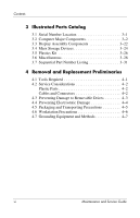 5
5 -
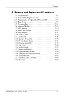 6
6 -
 7
7 -
8
-
9
-
10
-
11
-
12
-
13
-
14
-
15
-
16
-
17
-
18
-
19
-
20
-
21
-
22
-
23
-
24
-
25
-
26
-
27
-
28
-
29
-
30
-
31
-
32
-
33
-
34
-
35
-
36
-
37
-
38
-
39
-
40
-
41
-
42
-
43
-
44
-
45
-
46
-
47
-
48
-
49
-
50
-
51
-
52
-
53
-
54
-
55
-
56
-
57
-
58
-
59
-
60
-
61
-
62
-
63
-
64
-
65
-
66
-
67
-
68
-
69
-
70
-
71
-
72
-
73
-
74
-
75
-
76
-
77
-
78
-
79
-
80
-
81
-
82
-
83
-
84
-
85
-
86
-
87
-
88
-
89
-
90
-
91
-
92
-
93
-
94
-
95
-
96
-
97
-
98
-
99
-
100
-
101
-
102
-
103
-
104
-
105
-
106
-
107
-
108
-
109
-
110
-
111
-
112
-
113
-
114
-
115
-
116
-
117
-
118
-
119
-
120
-
121
-
122
-
123
-
124
-
125
-
126
-
127
-
128
-
129
-
130
-
131
-
132
-
133
-
134
-
135
-
136
-
137
-
138
-
139
-
140
-
141
-
142
-
143
-
144
-
145
-
146
-
147
-
148
-
149
-
150
-
151
-
152
-
153
-
154
-
155
-
156
-
157
-
158
-
159
-
160
-
161
-
162
-
163
-
164
-
165
-
166
-
167
-
168
-
169
-
170
-
171
-
172
-
173
-
174
-
175
-
176
-
177
-
178
-
179
-
180
-
181
-
182
-
183
-
184
-
185
-
186
-
187
-
188
-
189
-
190
-
191
-
192
-
193
-
194
-
195
-
196
-
197
-
198
-
199
-
200
-
201
-
202
-
203
-
204
-
205
-
206
-
207
-
208
-
209
-
210
-
211
-
212
-
213
-
214
-
215
-
216
-
217
-
218
-
219
-
220
-
221
-
222
-
223
-
224
-
225
-
226
-
227
-
228
-
229
-
230
-
231
-
232
-
233
-
234
-
235
-
236
-
237
-
238
-
239
-
240
-
241
-
242
-
243
-
244
-
245
-
246
-
247
-
248
-
249
-
250
-
251
-
252
-
253
-
254
-
255
-
256
-
257
-
258
-
259
-
260
-
261
-
262
-
263
-
264
-
265
-
266
-
267
-
268
-
269
-
270
-
271
-
272
-
273
-
274
-
275
-
276
-
277
-
278
 |
 |

Maintenance and Service
Guide
HP Pavilion dv6000 Notebook PC
Document Part Number:
416618-003
April 2007
This guide is a troubleshooting reference used for maintaining
and servicing the computer. It provides comprehensive
information on identifying computer features, components, and
spare parts; troubleshooting computer problems; and performing
computer disassembly procedures.