HP Dx2400 Service Reference Guide: HP Compaq dx2400 Business PC
HP Dx2400 - Compaq Business Desktop Manual
 |
UPC - 884962251881
View all HP Dx2400 manuals
Add to My Manuals
Save this manual to your list of manuals |
HP Dx2400 manual content summary:
- HP Dx2400 | Service Reference Guide: HP Compaq dx2400 Business PC - Page 1
Service Reference Guide HP Compaq dx2400 Business PC - HP Dx2400 | Service Reference Guide: HP Compaq dx2400 Business PC - Page 2
that is protected by copyright. No part of this document may be photocopied, reproduced, or translated to another language without the prior written consent of Hewlett-Packard Company. Service Reference Guide Business PCs First Edition (March 2008) Document Part Number: 484984-001 - HP Dx2400 | Service Reference Guide: HP Compaq dx2400 Business PC - Page 3
Installing or Upgrading Device Drivers 1 HP Backup and Recovery Manager ...2 2 Computer Setup (F10) Utility Computer Setup (F10) Utilities ...3 Using Computer Setup (F10) Utilities 3 Computer Setup-Main ...4 Computer Setup-Advanced 5 Computer Setup-Power ...6 Computer Setup-Boot ...7 Computer - HP Dx2400 | Service Reference Guide: HP Compaq dx2400 Business PC - Page 4
...23 Cleaning the Mouse ...23 Service Considerations ...23 Power Supply Fan ...23 Tools and Software Requirements 23 Screws ...24 Cables and Connectors ...24 Hard Drives ...24 Lithium Coin Cell Battery 25 6 Removal and Replacement Procedures Microtower (MT) Chassis Serial Number Location ...26 - HP Dx2400 | Service Reference Guide: HP Compaq dx2400 Business PC - Page 5
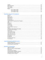
Speaker ...62 Rear Chassis Fan ...63 Power Supply ...64 System Board ...65 Battery ...66 Type 1 Battery Holder ...67 Type 2 Battery Holder ...67 Type 3 Battery Holder ...68 Appendix A Connector Pin Assignments Keyboard ...69 Mouse ...69 Ethernet BNC ...69 Ethernet RJ-45 ...70 Ethernet AUI ...70 - HP Dx2400 | Service Reference Guide: HP Compaq dx2400 Business PC - Page 6
Appendix D System Board and Riser Board Reference Designators ...92 Appendix E Specifications Index ...100 vi - HP Dx2400 | Service Reference Guide: HP Compaq dx2400 Business PC - Page 7
the appropriate drivers. Obtain the latest support software , including support software for the operating system from http://www.hp.com/support. Select your country and language, select Download drivers and software, enter the model number of the computer, and press Enter. Installing the Operating - HP Dx2400 | Service Reference Guide: HP Compaq dx2400 Business PC - Page 8
back up and recover the primary hard drive on the PC. The application works within Windows to create backups of Windows, all applications, and all data files. Backups can be scheduled to occur automatically at designated intervals, or they can be initiated manually. Important files can be archived - HP Dx2400 | Service Reference Guide: HP Compaq dx2400 Business PC - Page 9
view, change, or verify the system configuration, including settings for graphics, audio, storage, communications, and input devices. ● View settings for processor and memory. ● Modify the boot order of bootable devices such as hard drives, diskette drives, optical drives, or USB flash media devices - HP Dx2400 | Service Reference Guide: HP Compaq dx2400 Business PC - Page 10
CAUTION: Do NOT turn the computer power OFF while the ROM is saving the Computer Setup (F10) changes because the CMOS could become corrupted. It is safe to turn off the computer only after exiting the F10 Setup screen. Computer Setup-Main NOTE: Support for specific Computer Setup options may vary - HP Dx2400 | Service Reference Guide: HP Compaq dx2400 Business PC - Page 11
depending on the hardware configuration. WARNING! Setting items on this menu to incorrect values may cause your system to malfunction. Table 2-2 Computer Setup-Advanced Option Description CPU Type (view only) CPU Speed (view only) Cache RAM (view only) Primary Video Adapter Allows you to - HP Dx2400 | Service Reference Guide: HP Compaq dx2400 Business PC - Page 12
NOTE: Support for specific Computer Setup options may vary depending on the hardware configuration. Table 2-3 Computer Setup-Power Option Description After AC Power Failure Allows you to select system restart behavior after power loss: ● Stay Off ● Power On ● Auto XD Disables/enables XD bit - HP Dx2400 | Service Reference Guide: HP Compaq dx2400 Business PC - Page 13
device priority within hard drives. Priority Network Group Boot Priority Specifies boot device priority within bootable network devices. Computer Setup-Exit NOTE: Support for specific Computer Setup options may vary depending on the hardware configuration. Table 2-5 Computer Setup-Exit Option - HP Dx2400 | Service Reference Guide: HP Compaq dx2400 Business PC - Page 14
Settings To reset all BIOS Setup options to their default values (including options for ctrl+F10), you must enter F10 Setup mode and press F5. This does not include updates to system date, system time, supervisor password, user password, and CPU frequency multiplier. 8 Chapter 2 Computer Setup (F10 - HP Dx2400 | Service Reference Guide: HP Compaq dx2400 Business PC - Page 15
) and click Next. 3. Follow the instructions in the wizard to create a Recovery Disc Set. 4. Use Windows Explorer to search the Recovery Disc Set for the CD with the compaq\hpdiags directory. 5. While the computer is on, insert the CD into an optical drive on the computer. HP Insight Diagnostics 9 - HP Dx2400 | Service Reference Guide: HP Compaq dx2400 Business PC - Page 16
Memory-Shows information about all memory in the computer. This includes memory slots on the system board and any memory modules installed. Miscellaneous-Shows HP Insight Diagnostics version information, computer configuration memory (CMOS) information, system board data, and system management BIOS - HP Dx2400 | Service Reference Guide: HP Compaq dx2400 Business PC - Page 17
of the current set of tests. While testing is in progress, a Cancel Testing button is displayed for use if you want to cancel the test. HP Insight Diagnostics 11 - HP Dx2400 | Service Reference Guide: HP Compaq dx2400 Business PC - Page 18
replaced The Error Code provides a numerical code for the failure. The error codes are HP Insight Diagnostics tab, an Error Codes tab, and a Test Components tab. The HP problem. To find an error code description quickly, enter the code in the box at the top of the tab and click the Find Error Codes - HP Dx2400 | Service Reference Guide: HP Compaq dx2400 Business PC - Page 19
number (for example, dx2400) in the text box and press the Enter key. 4. Select your specific computer model. 5. Select your OS. 6. Click the Diagnostic link. 7. Click HP Insight Diagnostics Offline Edition. 8. Select a language and click Download. NOTE: The download includes instructions on how to - HP Dx2400 | Service Reference Guide: HP Compaq dx2400 Business PC - Page 20
back up and recover the primary hard drive on the PC. The application works within Windows to create backups of Windows, all applications, and all data files. Backups can be scheduled to occur automatically at designated intervals, or they can be initiated manually. Important files can be archived - HP Dx2400 | Service Reference Guide: HP Compaq dx2400 Business PC - Page 21
ATA = SATA Parallel ATA = PATA SATA Hard Drives Serial ATA Hard Drive Characteristics Number of pins/conductors in data cable Number of pins in power cable Maximum data cable length Data interface voltage differential Drive voltages Jumpers for configuring drive Data transfer rate 7/7 15 39.37 in - HP Dx2400 | Service Reference Guide: HP Compaq dx2400 Business PC - Page 22
SATA 3.0 Gb/s cable as it is fully backwards compatible with the SATA 1.5 Gb/s drives. Current HP desktop products ship with SATA 3.0 Gb/s hard drives. SATA data cables are susceptible to damage if overflexed. Never crease a SATA data cable and never bend it tighter than a 30 mm (1.18 in) radius - HP Dx2400 | Service Reference Guide: HP Compaq dx2400 Business PC - Page 23
drives are supported on any other model. ATA SMART Drives The Self Monitoring Analysis and Recording Technology (SMART) ATA drives for the HP Personal Computers have built-in drive failure prediction that warns the user or network administrator of an impending failure or crash of the hard drive - HP Dx2400 | Service Reference Guide: HP Compaq dx2400 Business PC - Page 24
for proper service. CAUTION: When the computer is plugged into an AC power source, voltage is always applied to the system board. You must disconnect the power cord from the power source before opening the computer to prevent system board or component damage. Chassis Designation Microtower (MT) 18 - HP Dx2400 | Service Reference Guide: HP Compaq dx2400 Business PC - Page 25
expectancy. Networks built into many integrated circuits provide some protection, but in many cases, the discharge contains enough power to alter and assemblies with conductive or approved containers or packaging. ● Keep electrostatic sensitive parts in their containers until they arrive at static - HP Dx2400 | Service Reference Guide: HP Compaq dx2400 Business PC - Page 26
Handle them only at static-free work areas. ● Turn off power and input signals before inserting and removing connectors or Keep work area free of nonconductive materials such as ordinary plastic assembly aids and Styrofoam. ● Use field service the Chassis, Routine Care, and Disassembly Preparation - HP Dx2400 | Service Reference Guide: HP Compaq dx2400 Business PC - Page 27
resistance ● Static-dissipative table or floor mats with hard tie to ground ● Field service kits ● Static awareness labels ● Wrist straps and Keep liquids away from the computer and keyboard. ● Never cover the ventilation slots on the monitor with any type of material. ● Install or enable power - HP Dx2400 | Service Reference Guide: HP Compaq dx2400 Business PC - Page 28
the keyboard body, follow the procedures described in Cleaning the Computer Case on page 22. When cleaning debris from under the keys, review all rules in General Cleaning Safety Precautions on page 22 the wide keys. 22 Chapter 5 Identifying the Chassis, Routine Care, and Disassembly Preparation - HP Dx2400 | Service Reference Guide: HP Compaq dx2400 Business PC - Page 29
some of the considerations that you should keep in mind during the disassembly and assembly of the computer. Power Supply Fan The power supply fan is a variable-speed fan based on the temperature in the power supply. CAUTION: The cooling fan is always on when the computer is in the "On" mode. The - HP Dx2400 | Service Reference Guide: HP Compaq dx2400 Business PC - Page 30
package for storage. Keep hard drives in their protective packaging until they are actually mounted in the CPU. ● Avoid dropping drives from any height onto any surface. ● If you are inserting or removing a hard drive, turn off the computer. Do not remove a hard drive while the computer is on or in - HP Dx2400 | Service Reference Guide: HP Compaq dx2400 Business PC - Page 31
with the computer provides power to the real-time clock and has a minimum lifetime of about three years. See the appropriate removal and replacement chapter for the chassis you are working on in this guide for instructions on the replacement procedures. WARNING! This computer contains a lithium - HP Dx2400 | Service Reference Guide: HP Compaq dx2400 Business PC - Page 32
computers. Serial Number Location Each computer has a unique serial number and product ID number that are located on the top of the computer. Keep these numbers available for use when contacting customer service for assistance. 26 Chapter 6 Removal and Replacement Procedures Microtower (MT) Chassis - HP Dx2400 | Service Reference Guide: HP Compaq dx2400 Business PC - Page 33
card from the computer. 5. Turn off the computer and any peripheral devices that are connected to it. CAUTION: Turn off the computer before disconnecting any cables. Regardless of the power and routing. Keep all screws with the units removed. CAUTION: The screws used in the computer are of different - HP Dx2400 | Service Reference Guide: HP Compaq dx2400 Business PC - Page 34
External Security Devices The following security devices are used to prevent unauthorized access to the internal components of the computer and/or secure the computer to a fixed object. Cable Lock Padlock 28 Chapter 6 Removal and Replacement Procedures Microtower (MT) Chassis - HP Dx2400 | Service Reference Guide: HP Compaq dx2400 Business PC - Page 35
HP Business PC Security Lock 1. Fasten the security cable by looping it around a stationary object. 2. Thread the keyboard and mouse cables through the lock. External Security Devices 29 - HP Dx2400 | Service Reference Guide: HP Compaq dx2400 Business PC - Page 36
3. Screw the lock to the chassis using the screw provided. 4. Insert the plug end of the security cable into the lock (1) and push the button in (2) to engage the lock. Use the key provided to disengage the lock. 30 Chapter 6 Removal and Replacement Procedures Microtower (MT) Chassis - HP Dx2400 | Service Reference Guide: HP Compaq dx2400 Business PC - Page 37
ensure that the computer is turned off and that the power cord is disconnected from the electrical outlet. 2. Loosen the screw (1) that secures the access panel to the computer chassis. 3. Slide the access panel back (2) about 1.3 cm (1/2 inch), then lift it off the unit. To install the access panel - HP Dx2400 | Service Reference Guide: HP Compaq dx2400 Business PC - Page 38
31). 3. Press outward on the three latches on the right side of the bezel (1), then rotate the right side of the bezel off the chassis (2) followed by the left side. To reinstall the front bezel, reverse the removal procedure. 32 Chapter 6 Removal and Replacement Procedures Microtower (MT) Chassis - HP Dx2400 | Service Reference Guide: HP Compaq dx2400 Business PC - Page 39
Removing Bezel Blanks On some models, there are bezel blanks covering the 3.5-inch and 5.25-inch external drive bays that need to be removed before installing a drive. To remove a bezel blank: 1. Remove the front bezel. 2. To remove a 5.25-inch blank, break the blank out of the bezel (1). - or - To - HP Dx2400 | Service Reference Guide: HP Compaq dx2400 Business PC - Page 40
the computer. ● Keep cables away from major heat sources like the heatsink. ● Do not jam cables on top of expansion cards or memory modules. Printed circuit cards cable could damage the cable and result in a failed power supply. 34 Chapter 6 Removal and Replacement Procedures Microtower (MT) Chassis - HP Dx2400 | Service Reference Guide: HP Compaq dx2400 Business PC - Page 41
board connectors are color-coded to make it easier to Power supply, 24-pin Power supply, 4-pin Diskette drive Heatsink fan Chassis fan Front power button/LED Front I/O USB Media card reader Front I/O audio Internal speaker Memory slots PCI 2.3 full-height slot PCI Express X1 slot PCI Express X1 slot - HP Dx2400 | Service Reference Guide: HP Compaq dx2400 Business PC - Page 42
memory support, you can populate the system board with up to 4 GB of memory configured , the computer supports: ● 512Mbit and 1Gbit non-ECC memory technologies ● memory channel A. Sockets XMM3 and XMM4 operate in memory channel B. 36 Chapter 6 Removal and Replacement Procedures Microtower (MT) Chassis - HP Dx2400 | Service Reference Guide: HP Compaq dx2400 Business PC - Page 43
A 3 DIMM socket XMM3, Channel B (populate second) 4 DIMM socket XMM4, Channel B NOTE: flex mode, depending on how the DIMMs are installed. ● The system will operate in single channel mode mode if the total memory capacity of the DIMMs in Channel A is equal to the total memory capacity of the - HP Dx2400 | Service Reference Guide: HP Compaq dx2400 Business PC - Page 44
(3). 5. Repeat steps 3 and 4 for any additional modules that you want to install. NOTE: The computer automatically recognizes the additional memory when turned on. To reassemble the computer, reverse the removal procedure. 38 Chapter 6 Removal and Replacement Procedures Microtower (MT) Chassis - HP Dx2400 | Service Reference Guide: HP Compaq dx2400 Business PC - Page 45
3 PCI Express x1 expansion slot 4 PCI Express x16 expansion slot NOTE: You can install a PCI Express x1, x4, x8, or x16 expansion card in the PCI Express x16 expansion slot. To remove, replace, or add an expansion card: 1. Prepare the computer for disassembly (Preparation for Disassembly on - HP Dx2400 | Service Reference Guide: HP Compaq dx2400 Business PC - Page 46
card in a vacant socket, you must use a flatblade screwdriver to pry out the metal shield on the rear panel that covers the expansion slot. Be sure to remove the appropriate shield for the expansion card you are installing. 40 Chapter 6 Removal and Replacement Procedures Microtower (MT) Chassis - HP Dx2400 | Service Reference Guide: HP Compaq dx2400 Business PC - Page 47
components. 6. Store the removed card in anti-static packaging. 7. If you are not installing a new expansion card, install an expansion slot cover to close the open slot. CAUTION: After removing an expansion card, you must replace it with a new card or expansion slot cover for proper cooling of - HP Dx2400 | Service Reference Guide: HP Compaq dx2400 Business PC - Page 48
to the installed card, if needed. Connect internal cables to the system board, if needed. 11. Reconfigure the computer, if necessary. Refer to Computer Setup (F10) Utility on page 3 for instructions on using Computer Setup. 42 Chapter 6 Removal and Replacement Procedures Microtower (MT) Chassis - HP Dx2400 | Service Reference Guide: HP Compaq dx2400 Business PC - Page 49
● Connect a media card reader to the USB connector labeled F_USB2. ● The system does not support Parallel ATA (PATA) optical drives or PATA hard drives. ● You may install either a third-height or a half-height drive into a half-height bay. ● If needed, HP has provided extra drive retainer screws on - HP Dx2400 | Service Reference Guide: HP Compaq dx2400 Business PC - Page 50
extremes, or products that have magnetic fields such as monitors or speakers. If a drive must be mailed, place the drive in a bubble-pack mailer or other protective packaging and label the package "Fragile: Handle With Care." 44 Chapter 6 Removal and Replacement Procedures Microtower (MT) Chassis - HP Dx2400 | Service Reference Guide: HP Compaq dx2400 Business PC - Page 51
Card Reader F_USB2 2 SATA0 SATA0 3 SATA1 SATA1 4 SATA2 SATA2 5 SATA3 SATA3 6 Diskette Drive FLOPPY Color white dark blue white light blue orange black To verify the type, size, and capacity of the storage devices installed in the computer, run Computer Setup. Refer to Computer - HP Dx2400 | Service Reference Guide: HP Compaq dx2400 Business PC - Page 52
3.5-inch internal hard drive bay for optional hard drive To verify the type and size of the storage devices installed in the computer, run Computer Setup. Refer to Computer Setup (F10) Utility on page 3 for more information. 46 Chapter 6 Removal and Replacement Procedures Microtower (MT) Chassis - HP Dx2400 | Service Reference Guide: HP Compaq dx2400 Business PC - Page 53
(Computer Access Panel on page 31). 3. Remove the front bezel (Front Bezel on page 32). 4. Disconnect the power cable (1) and data cable (2) from the rear of the optical drive. 5. Remove the screws that secure the drive to the drive cage (1), then slide the drive out of the front of the chassis - HP Dx2400 | Service Reference Guide: HP Compaq dx2400 Business PC - Page 54
only one optical drive, connect the SATA data cable to the white system board connector labeled SATA1 . If you are adding a second optical drive, connect the SATA data cable to the orange system board connector labeled SATA3. 48 Chapter 6 Removal and Replacement Procedures Microtower (MT) Chassis - HP Dx2400 | Service Reference Guide: HP Compaq dx2400 Business PC - Page 55
be taken out of a drive before removing the drive from the computer. NOTE: The 3.5-inch drive bay may contain a diskette drive or a media card reader. 1. Prepare the computer for disassembly (Preparation for Disassembly on page 27). 2. Remove the computer access panel (Computer Access Panel on page - HP Dx2400 | Service Reference Guide: HP Compaq dx2400 Business PC - Page 56
illustrations: a. If you are removing a diskette drive, disconnect the data cable (1) and power cable (2) from the back of the drive. b. If you are removing a media card reader, disconnect the USB cable from the system board. 50 Chapter 6 Removal and Replacement Procedures Microtower (MT) Chassis - HP Dx2400 | Service Reference Guide: HP Compaq dx2400 Business PC - Page 57
bay (1) then slide the drive forward and out of the bay (2). Installing a Drive into the 3.5-inch External Drive Bay The 3.5-inch external drive bay on the front of the computer can be configured with a media card reader or a diskette drive. 1. Prepare the computer for disassembly (Preparation for - HP Dx2400 | Service Reference Guide: HP Compaq dx2400 Business PC - Page 58
Board Drive Connections on page 45 for an illustration of the system board drive connectors. 9. Replace the front bezel and access panel. 10. Lock any security devices that were disengaged when the access panel was removed. 52 Chapter 6 Removal and Replacement Procedures Microtower (MT) Chassis - HP Dx2400 | Service Reference Guide: HP Compaq dx2400 Business PC - Page 59
you can transfer the data to the new hard drive. Also, if you are replacing the primary hard drive, make sure you have created a Recovery Disc Set to restore the operating system, software drivers, and any software applications that were preinstalled on the computer. If you do not have this CD set - HP Dx2400 | Service Reference Guide: HP Compaq dx2400 Business PC - Page 60
5. Lift the hard disk drive cage out of the chassis. 6. Disconnect the power cable (1) and data cable (2) from the back of the hard drive. 54 Chapter 6 Removal and Replacement Procedures Microtower (MT) Chassis - HP Dx2400 | Service Reference Guide: HP Compaq dx2400 Business PC - Page 61
four screws that secure the hard disk drive to the hard disk drive cage (1), then slide the hard disk drive out of the hard disk drive cage (2). Installing an Internal 3.5-inch Hard Drive 1. Follow the steps in Removing an Internal 3.5-inch Hard Drive on page 53 to remove the hard drive cage and, if - HP Dx2400 | Service Reference Guide: HP Compaq dx2400 Business PC - Page 62
are silver. 3. Connect the power cable (1) and data cable (2) to the back of the hard drive. CAUTION: Never crease or bend a SATA data cable tighter than a 30 mm (1.18 in) radius. A sharp bend can break the internal wires. 56 Chapter 6 Removal and Replacement Procedures Microtower (MT) Chassis - HP Dx2400 | Service Reference Guide: HP Compaq dx2400 Business PC - Page 63
labeled SATA0 to avoid any hard drive performance problems. If you are adding a second hard drive, connect the data cable to the next available (unpopulated) SATA connector on the system board in the following order: SATA0, SATA1, SATA3, SATA2. 7. Replace the computer access panel. 8. Lock any - HP Dx2400 | Service Reference Guide: HP Compaq dx2400 Business PC - Page 64
NOTE: If you are replacing the primary hard drive, use the Recovery Disc Set to restore the operating system, software drivers, and any software applications that were preinstalled on the computer. Front USB Panel 1. Prepare the computer for disassembly (Preparation for Disassembly on page 27). 2. - HP Dx2400 | Service Reference Guide: HP Compaq dx2400 Business PC - Page 65
Power Switch/LED Assembly 1. Prepare the computer for disassembly (Preparation for Disassembly on page 27). 2. Remove the computer access panel (Computer Access Panel on page 31). 3. Remove the front bezel (Front Bezel on page 32). 4. Remove the optical drive (Removing an Optical Drive on page 47). - HP Dx2400 | Service Reference Guide: HP Compaq dx2400 Business PC - Page 66
on page 27). 2. Remove the computer access panel (Computer Access Panel on page 31). 3. Unplug the fan cable from the system board (CPU FAN). 4. Using a screwdriver with any damage to them may require replacing the system board. 60 Chapter 6 Removal and Replacement Procedures Microtower (MT) Chassis - HP Dx2400 | Service Reference Guide: HP Compaq dx2400 Business PC - Page 67
Preparation for Disassembly on page 27). 2. Remove the computer access panel (Computer Access Panel on page 31). 3. Remove the replace the system board. The heatsink must be installed within 24 hours of installing the processor to prevent damage to the processor's solder connections. To install - HP Dx2400 | Service Reference Guide: HP Compaq dx2400 Business PC - Page 68
may require replacing the system board. NOTE: After installing a new processor onto the system board, always update the system ROM to ensure that the latest version of the BIOS is being used on the computer. The latest system BIOS can be found on the Web at: http://h18000.www1.hp.com/support/files - HP Dx2400 | Service Reference Guide: HP Compaq dx2400 Business PC - Page 69
When replacing the speaker, be sure to route the wire behind the hard drive cage bracket, through the metal clamp on the chassis, through the metal clamp on the side of the second hard drive cage, and then down to the system board. Rear Chassis Fan 1. Prepare the computer for disassembly ( - HP Dx2400 | Service Reference Guide: HP Compaq dx2400 Business PC - Page 70
tab in front of the power supply that holds it in place, pull the power supply up slightly to loosen it from the chassis. 6. Lift the power supply out of the chassis. To install the power supply, reverse the removal procedure. 64 Chapter 6 Removal and Replacement Procedures Microtower (MT) Chassis - HP Dx2400 | Service Reference Guide: HP Compaq dx2400 Business PC - Page 71
out of the computer. When reinstalling the system board, first insert the I/O panel back into the slots in the rear of the chassis, and then align the board with the chassis screw holes. NOTE: When replacing the system board, you must change the chassis serial number in the BIOS. System Board 65 - HP Dx2400 | Service Reference Guide: HP Compaq dx2400 Business PC - Page 72
card to gain access to the battery. 3. Locate the battery and battery holder on the system board. 4. Depending on the type of battery holder on your system board, complete the following instructions to replace the battery: 66 Chapter 6 Removal and Replacement Procedures Microtower (MT) Chassis - HP Dx2400 | Service Reference Guide: HP Compaq dx2400 Business PC - Page 73
automatically secures the battery in the proper position. 4. Replace the computer access panel. 5. Plug in the computer and turn on power to the computer. 6. Reset the date and time and any special system setups using Computer Setup. Refer to Computer Setup (F10) Utility on page 3. Type 2 Battery - HP Dx2400 | Service Reference Guide: HP Compaq dx2400 Business PC - Page 74
. 3. Replace the computer access panel. 4. Plug in the computer and turn on power to the computer. 5. Reset the date and time and any special system setups using Computer Setup. Refer to Computer Setup (F10) Utility on page 3. 68 Chapter 6 Removal and Replacement Procedures Microtower (MT) Chassis - HP Dx2400 | Service Reference Guide: HP Compaq dx2400 Business PC - Page 75
and workstation connectors. Some of these connectors may not be used on the product being serviced. Keyboard Connector and Icon Pin Signal 1 Data 2 Unused 3 Ground 4 +5 VDC 5 Clock 6 Unused Mouse Connector and Icon Pin Signal 1 Data 2 Unused 3 Ground 4 +5 VDC 5 Clock - HP Dx2400 | Service Reference Guide: HP Compaq dx2400 Business PC - Page 76
RJ-45 Connector and Icon Ethernet AUI Connector and Icon Pin Signal 1 Ground 2 Negative AUI Differential Collision 3 Positive AUI Differential Collision 4 Negative AUI Differential Transmit 5 Positive AUI Differential Transmit 6 Ground 7 Ground 8 - HP Dx2400 | Service Reference Guide: HP Compaq dx2400 Business PC - Page 77
Data Bit 0 3 Data Bit 1 4 Data Bit 2 5 Data Bit 3 6 Data Bit 4 7 Data Bit 5 8 Data Bit 6 9 Data Bit 7 Pin Signal 10 Acknowledge 11 Busy 12 Paper End 13 Select 14 Auto Linefeed 15 Error 16 Initialize Printer 17 Select IN 18-25 Signal Ground Serial Interface, Powered - HP Dx2400 | Service Reference Guide: HP Compaq dx2400 Business PC - Page 78
USB Connector and Icon Microphone Connector and Icon (1/8" miniphone) 1 23 Headphone Connector and Icon (1/8" miniphone) 1 23 Line-in Audio Connector and Icon (1/8" miniphone) 1 23 Line-out Audio Connector and Icon (1/8" miniphone) 1 23 72 Appendix A Connector Pin Assignments Pin Signal 1 +5 VDC - HP Dx2400 | Service Reference Guide: HP Compaq dx2400 Business PC - Page 79
External Infrared Transceiver Connector and Icon Monitor Connector and Icon Pin Signal 1 Transmit 2 Receive 3 Ground 4 5V 5 Mode 6 Not Used 7 Not Used 8 Not Used Pin Signal 1 Red Analog 2 Green Analog 3 Blue Analog 4 Not used 5 Ground 6 Ground 7 Ground 8 Ground - HP Dx2400 | Service Reference Guide: HP Compaq dx2400 Business PC - Page 80
ATA/ATAPI (IDE) Standard Drive Cable Connector Pin Signal 1 Reset 2 Ground 3 DD7 4 DD8 5 DD6 6 DD9 7 DD5 8 DD10 9 DD4 10 DD11 11 DD3 12 DD12 13 DD2 14 DD13 Pin Signal 15 DD1 16 DD14 17 - HP Dx2400 | Service Reference Guide: HP Compaq dx2400 Business PC - Page 81
CD-ROM 50-Pin Connector Connector Pin Signal 1 Audio L-ch 2 Audio R-ch 3 Audio GND 4 GND 5 RESET 6 DD8 7 DD7 8 DD9 9 DD6 10 DD10 11 DD5 12 DD11 13 DD4 24-Pin Power Connector 24 12 Pin Signal 1 +3.3V 2 +3.3V 3 GND 4 +5V 5 GND 6 +5V Pin Signal 14 DD12 15 DD3 16 - HP Dx2400 | Service Reference Guide: HP Compaq dx2400 Business PC - Page 82
11 GND 12 Fan-CMD Front Pin Signal 13 +12V 14 +5V Sense 15 GND 16 +5V 17 +5V 18 +3.3V Pin Signal 19 GND 20 +3.3V 21 Sense 22 +3.3V 23 +3.3V 24 GND 4-Pin Power (for CPU) Connector and Icon Pin Signal 1 GND 2 GND 3 +12V CPU 4 -12V CPU 6-Pin Power (for CPU) Connector and Icon - HP Dx2400 | Service Reference Guide: HP Compaq dx2400 Business PC - Page 83
SATA Data and Power Drive Connector Pin Signal S1 Ground S5 BP1 Ground P5 BP9 V 5 P13 V 12 S = Data, P = Power Pin Signal S2 A+ S6 B+ P2 V 3.3 P6 Ground P10 Ground P14 V12 PCI Express x1, x4, x8, and x16 PCI 24 GND 25 PERp2 46 GND 47 PERp7 48 PERn7 49 GND 50 RSVD 71 GND SATA Data and Power 77 - HP Dx2400 | Service Reference Guide: HP Compaq dx2400 Business PC - Page 84
Express uses pins 1-18 x4 PCI Express uses pins 1-32 x8 PCI Express uses pins 1-49 x16 PCI Express uses pins 1-8 62 GND 63 GND 64 PERp11 65 PERn11 PCI Express x1, x4, x8, and x16 PCI Express Connector 67 GND 68 PERp12 69 PERn12 70 GND 72 PERp13 73 PERn13 - HP Dx2400 | Service Reference Guide: HP Compaq dx2400 Business PC - Page 85
32 x8 PCI Express uses pins 1-49 x16 PCI Express uses pins 1-8 62 PETp11 63 PETn11 64 GND 65 GND PCI Express Mini Card PCI Express Mini Card Connector 67 PETn12 68 GND 69 GND 70 PETp13 72 GND 73 GND 74 PETp14 75 PETn14 25 PERp0 26 GND 27 GND 28 +1.5V 29 GND 30 SMB_CLK PCI Express Mini Card 79 - HP Dx2400 | Service Reference Guide: HP Compaq dx2400 Business PC - Page 86
36 USB_D- 42 LED_WWAN# 48 +1.5V NOTE: *Reserved for future second PCI Express LAN (if needed) **Reserved for future wireless coexistence control interface /3 Shield 12 T.M.D.S. Data3- Pin Signal 13 T.M.D.S. Data3+ 14 +5V Power 15 Ground (for +5V) 16 Hot Pug Detect 17 T.M.D.S. Data0- - HP Dx2400 | Service Reference Guide: HP Compaq dx2400 Business PC - Page 87
B Power Cord Set Requirements The power supplies on some computers have external power switches. The voltage select switch feature on the computer permits it to operate from any line voltage between 100-120 or 220-240 volts AC. Power supplies on those computers that do not have external power - HP Dx2400 | Service Reference Guide: HP Compaq dx2400 Business PC - Page 88
1. The flexible cord must be Type HO5VV-F, 3-conductor, 0.75mm2 conductor size. Power cord set fittings (appliance coupler and wall plug) must bear the certification mark of grounding type with a Japanese Industrial Standard C8303 (7A, 125V) configuration. 82 Appendix B Power Cord Set Requirements - HP Dx2400 | Service Reference Guide: HP Compaq dx2400 Business PC - Page 89
isolate the exact problem before calling for technical support. ● Run the HP diagnostic tool. ● Run the hard drive self-test in Computer Setup. Refer to Computer Setup (F10) Utility on page 3 for more information. ● Listen for a series of beeps from the computer. The beeps are error codes that will - HP Dx2400 | Service Reference Guide: HP Compaq dx2400 Business PC - Page 90
number before calling. ● Spend time troubleshooting the problem with the service technician. ● Remove any hardware that was recently added to your system. ● Remove any software that was recently installed. NOTE: For sales information and warranty upgrades (Care Packs), call your local authorized - HP Dx2400 | Service Reference Guide: HP Compaq dx2400 Business PC - Page 91
switch on rear of computer chassis (some Select the proper AC voltage using the selector switch. models) not switched to correct line voltage (115V or 230V). A defective PCI card has been installed. Remove any expansion board that was just installed. Drive data or power supply cables may not be - HP Dx2400 | Service Reference Guide: HP Compaq dx2400 Business PC - Page 92
life of the RTC battery. First, reset the date and time under Control Panel (Computer Setup can also be used to update the RTC date and time). If the problem persists, replace the RTC battery. See the Hardware Reference Guide for instructions on installing a new battery, or contact an authorized - HP Dx2400 | Service Reference Guide: HP Compaq dx2400 Business PC - Page 93
Windows XP) or Start > All Programs > Accessories > Run (Microsoft Windows Vista) and type msconfig. On the Startup tab of the System Configuration more memory. Cause unknown. 3. Upgrade the graphics solution. Restart the computer. Blank screen (no video). Cause Solution Monitor is not turned - HP Dx2400 | Service Reference Guide: HP Compaq dx2400 Business PC - Page 94
code. Solving Hardware Installation Problems You may need to reconfigure the computer when you add or remove hardware, such as an additional drive or expansion card. If you install a plug and play device, the Windows operating system automatically recognizes the device and configures the computer - HP Dx2400 | Service Reference Guide: HP Compaq dx2400 Business PC - Page 95
using the correct memory modules and to verify the proper installation. 2. Listen for beeps from the computer. See Interpreting POST Audible Codes on page 90 to determine possible causes. 3. If you still cannot resolve the issue, contact Customer Support. Solving Hardware Installation Problems 89 - HP Dx2400 | Service Reference Guide: HP Compaq dx2400 Business PC - Page 96
, replace the system board. 3 short beeps and 1 long beep followed by a three second pause CPU configuration error or invalid CPU 1. detected before graphics card initialized. 2. Upgrade the BIOS to proper version. Change the processor. 1 short beep followed by a one No legacy floppy drive or - HP Dx2400 | Service Reference Guide: HP Compaq dx2400 Business PC - Page 97
http://www.hp.com. NOTE: If you take the computer to an authorized reseller, dealer, or service provider for service, remember to provide the setup and power-on passwords if they are set. Refer to the number listed in the warranty or in the Support Telephone Numbers guide for technical assistance - HP Dx2400 | Service Reference Guide: HP Compaq dx2400 Business PC - Page 98
Battery socket/Battery LED - 5V_Aux (on) Health-LED UID LED Power LED Hard drive activity LED Boot block header/jumper Boot block recovery header ROM recovery header 1394 connector Second IEEE 1394 connector SPDIF input SPDIF output PCI slots PCI extender slot (male) PCI Express slots Primary SCSI - HP Dx2400 | Service Reference Guide: HP Compaq dx2400 Business PC - Page 99
slot for graphics First parallel port Second parallel port Double-stacked parallel port, Top = Port B, Bottom = Port A Parallel port over single Serial Port Parallel port over Serial Port and Video Port Parallel port over dual VGA ports DVI connector Keyboard connector, PS/2 (Closest to power supply - HP Dx2400 | Service Reference Guide: HP Compaq dx2400 Business PC - Page 100
P4 Secondary Processor 12V header P5 Main Power/HDD LED connector P6 Speaker connector P7 Analog audio connector (from CD-ROM) P8 Primary chassis fan header or primary CPU heatsink fan P9 Secondary chassis fan header P10 Diskette drive connector P11 Auxiliary Audio connector P12 - HP Dx2400 | Service Reference Guide: HP Compaq dx2400 Business PC - Page 101
Graphics option connector Fifth Serial ATA (SATA) connector Sixth Serial ATA (SATA) connector Seventh Serial ATA (SATA) connector Eighth Serial ATA (SATA) connector Primary (CPU) fan header for fansink Secondary CPU fan reader header White box chassis fan header Security hood switch on riser card - HP Dx2400 | Service Reference Guide: HP Compaq dx2400 Business PC - Page 102
64 bit Bridge LOM1 LOM1 EEPROM LOM1 PHY Audio Codec Audio amplifier LOM2 LOM2 EEPROM LOM2 PHY SPI ROM - SOIC-8 footprint Fan controller SPI ROM - SO16 footprint TMDS controller Parallel port diode array First serial port transceiver Second serial port transceiver VRM controller USB front port power - HP Dx2400 | Service Reference Guide: HP Compaq dx2400 Business PC - Page 103
Y4 Y5/H5 Secondary NIC clock crystal RTC clock crystal/tie-down 97 - HP Dx2400 | Service Reference Guide: HP Compaq dx2400 Business PC - Page 104
Desktop Humidity (noncondensing) Operating 15-90% 15-90% Nonoperating (38.7°C max wet bulb) 15-90% 15-90% Maximum Altitude (unpressurized) Operating options installed. Heat Dissipation Maximum 1575 BTU/hr 397 kg-cal/hr Typical (idle) 307 BTU/hr 77 kg-cal/hr Power Supply 115V - HP Dx2400 | Service Reference Guide: HP Compaq dx2400 Business PC - Page 105
Table E-1 Specifications (continued) Rated Input Current (maximum)1 8A @ 100 VAC 4A @ 200 VAC 1 This system utilizes a passive power factor corrected power supply. The power factor correction is present in the 230V operating mode only. This allows the system to pass the CE mark requirements for - HP Dx2400 | Service Reference Guide: HP Compaq dx2400 Business PC - Page 106
70 expansion cards removal and replacement 39 expansion slot cover removing 40 replacing 41 external security 28 F fan, power supply 23 front bezel removal and replacement 32 removing blanks 33 front USB panel removal and replacement 58 G grounding methods 20 H hard drive installing 55 proper - HP Dx2400 | Service Reference Guide: HP Compaq dx2400 Business PC - Page 107
panel 58 heatsink 60 memory 36 power supply 64 power switch/LED assembly 59 processor 61 rear chassis fan 63 speaker 62 system board 65 removing bezel blanks 33 diskette drive 49 expansion slot cover 40 hard drive 53 media card reader 49 optical drive 47 PCI card 41 PCI Express card 41 riser board
-
 1
1 -
 2
2 -
 3
3 -
 4
4 -
 5
5 -
 6
6 -
 7
7 -
8
-
9
-
10
-
11
-
12
-
13
-
14
-
15
-
16
-
17
-
18
-
19
-
20
-
21
-
22
-
23
-
24
-
25
-
26
-
27
-
28
-
29
-
30
-
31
-
32
-
33
-
34
-
35
-
36
-
37
-
38
-
39
-
40
-
41
-
42
-
43
-
44
-
45
-
46
-
47
-
48
-
49
-
50
-
51
-
52
-
53
-
54
-
55
-
56
-
57
-
58
-
59
-
60
-
61
-
62
-
63
-
64
-
65
-
66
-
67
-
68
-
69
-
70
-
71
-
72
-
73
-
74
-
75
-
76
-
77
-
78
-
79
-
80
-
81
-
82
-
83
-
84
-
85
-
86
-
87
-
88
-
89
-
90
-
91
-
92
-
93
-
94
-
95
-
96
-
97
-
98
-
99
-
100
-
101
-
102
-
103
-
104
-
105
-
106
-
107
 |
 |

Service Reference Guide
HP Compaq dx2400 Business PC