HP ENVY dv4-5300 HP Envy dv4 Notebook PC Maintenance and Service Guide - Page 67
Fan/heat sink assembly, management/battery conservation configurations, battery fast charging
 |
View all HP ENVY dv4-5300 manuals
Add to My Manuals
Save this manual to your list of manuals |
Page 67 highlights
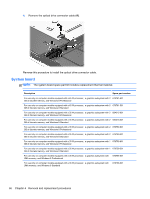
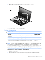
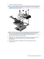
4. Remove the system board (3) by sliding it up and to the right at an angle. Reverse this procedure to install the system board. Fan/heat sink assembly NOTE: The fan/heat sink assembly spare part kit include replacement thermal material. Description For use only on computer models equipped with a graphics subsystem with GeForce 650M discrete memory For use only on computer models equipped with a graphics subsystem with GeForce 630M discrete memory For use only on computer models equipped with a graphics subsystem with UMA memory Spare part number 702120-001 681226-001 681225-001 NOTE: To properly ventilate the computer, allow at least 7.6 cm (3 in) of clearance on the left side of the computer. The computer uses an electric fan for ventilation. The fan is controlled by a temperature sensor and is designed to turn on automatically when high temperature conditions exist. These conditions are affected by high external temperatures, system power consumption, power management/battery conservation configurations, battery fast charging, and software requirements. Exhaust air is displaced through the ventilation grill located on the left side of the computer. Before removing the fan/heat sink assembly, follow these steps: 1. Shut down the computer. 2. Disconnect the power from the computer by unplugging the power cord from the computer. Component replacement procedures 59
-
 1
1 -
2
-
3
-
4
-
5
-
6
-
7
-
8
-
9
-
10
-
11
-
12
-
13
-
14
-
15
-
16
-
17
-
18
-
19
-
20
-
21
-
22
-
23
-
24
-
25
-
26
-
27
-
28
-
29
-
30
-
31
-
32
-
33
-
34
-
35
-
36
-
37
-
38
-
39
-
40
-
41
-
42
-
43
-
44
-
45
-
46
-
47
-
48
-
49
-
50
-
51
-
52
-
53
-
54
-
55
-
56
-
57
-
58
-
59
-
60
-
61
-
 62
62 -
 63
63 -
 64
64 -
 65
65 -
 66
66 -
 67
67 -
 68
68 -
 69
69 -
 70
70 -
 71
71 -
 72
72 -
73
-
74
-
75
-
76
-
77
-
78
-
79
-
80
-
81
-
82
-
83
-
84
-
85
-
86
-
87
-
88
-
89
-
90
-
91
-
92
-
93
-
94
-
95
-
96
-
97
-
98
-
99
-
100
-
101
-
102
-
103
-
104
-
105
-
106
 |
 |
