HP ENVY dv6t-7200 HP ENVY dv6 Notebook PC Maintenance and Service Guide IMPORT - Page 90
Fan/heat sink assembly
 |
View all HP ENVY dv6t-7200 manuals
Add to My Manuals
Save this manual to your list of manuals |
Page 90 highlights
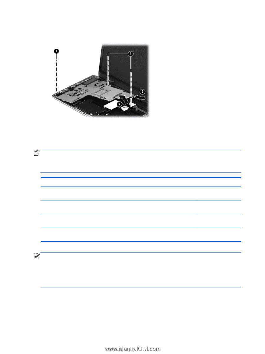
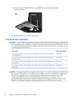
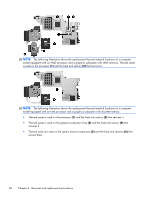
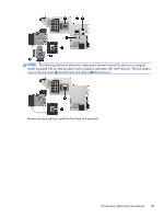
11. Remove the three Phillips PM2.5×5.5 screws (1) that secure the system board to the base enclosure. Reverse this procedure to install the system board. Fan/heat sink assembly NOTE: The fan/heat sink assembly spare part kit include replacement thermal material. Replacement thermal material is also available in the Thermal Material Kit, spare part numbers 685348-001 (for use on computer models equipped with an AMD processor) and 682100-001 (for use on computer models equipped with an Intel processor). Description Spare part number For use only on computer models equipped with an AMD processor and a graphics subsystem with discrete memory 682179-001 For use only on computer models equipped with an AMD processor and a graphics subsystem with UMA memory 682178-001 For use only on computer models equipped with an Intel processor and a graphics subsystem with 682061-001 discrete memory For use only on computer models equipped with an Intel processor and a graphics subsystem with 682060-001 UMA memory NOTE: To properly ventilate the computer, allow at least 7.6 cm (3 in) of clearance on the left side of the computer. The computer uses an electric fan for ventilation. The fan is controlled by a temperature sensor and is designed to turn on automatically when high temperature conditions exist. These conditions are affected by high external temperatures, system power consumption, power management/battery conservation configurations, battery fast charging, and software requirements. Exhaust air is displaced through the ventilation grill located on the left side of the computer. 82 Chapter 4 Removal and replacement procedures
-
 1
1 -
2
-
3
-
4
-
5
-
6
-
7
-
8
-
9
-
10
-
11
-
12
-
13
-
14
-
15
-
16
-
17
-
18
-
19
-
20
-
21
-
22
-
23
-
24
-
25
-
26
-
27
-
28
-
29
-
30
-
31
-
32
-
33
-
34
-
35
-
36
-
37
-
38
-
39
-
40
-
41
-
42
-
43
-
44
-
45
-
46
-
47
-
48
-
49
-
50
-
51
-
52
-
53
-
54
-
55
-
56
-
57
-
58
-
59
-
60
-
61
-
62
-
63
-
64
-
65
-
66
-
67
-
68
-
69
-
70
-
71
-
72
-
73
-
74
-
75
-
76
-
77
-
78
-
79
-
80
-
81
-
82
-
83
-
84
-
 85
85 -
 86
86 -
 87
87 -
 88
88 -
 89
89 -
 90
90 -
 91
91 -
 92
92 -
 93
93 -
 94
94 -
 95
95 -
96
-
97
-
98
-
99
-
100
-
101
-
102
-
103
-
104
-
105
-
106
-
107
-
108
-
109
-
110
-
111
-
112
-
113
-
114
-
115
-
116
-
117
-
118
-
119
-
120
-
121
-
122
-
123
-
124
-
125
-
126
-
127
-
128
-
129
-
130
 |
 |