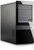
HP Elite 7100 Maintenance & Service Guide: HP Elite 7100 Series Microtower
HP Elite 7100 - Microtower PC Manual
 |
View all HP Elite 7100 manuals
Add to My Manuals
Save this manual to your list of manuals |
HP Elite 7100 manual content summary:
- HP Elite 7100 | Maintenance & Service Guide: HP Elite 7100 Series Microtower - Page 1
Maintenance & Service Guide HP Elite 7100 Series Microtower PC - HP Elite 7100 | Maintenance & Service Guide: HP Elite 7100 Series Microtower - Page 2
Microsoft and Windows are trademarks of Microsoft Corporation in the U.S. and other countries. The only warranties for HP products and services are consent of Hewlett-Packard Company. Maintenance & Service Guide HP Elite 7100 Series Microtower PC First Edition (February 2010) Document Part Number: - HP Elite 7100 | Maintenance & Service Guide: HP Elite 7100 Series Microtower - Page 3
About This Book WARNING! Text set off in this manner indicates that failure to follow directions could result in bodily harm or loss of life. CAUTION: Text set off in this manner indicates that failure to follow directions could result in damage to equipment or loss of information. NOTE: Text set - HP Elite 7100 | Maintenance & Service Guide: HP Elite 7100 Series Microtower - Page 4
iv About This Book - HP Elite 7100 | Maintenance & Service Guide: HP Elite 7100 Series Microtower - Page 5
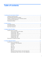
...2 Downloading Microsoft Windows Updates 2 Installing or Upgrading Device Drivers (Windows systems 2 Accessing Disk Image (ISO) Files ...3 Protecting the Software ...3 2 Product Features ...4 Serviceability Features ...4 Front Panel Components ...4 Rear Panel Components ...5 3 Computer Setup - HP Elite 7100 | Maintenance & Service Guide: HP Elite 7100 Series Microtower - Page 6
23 Cleaning the Computer Case 23 Cleaning the Keyboard ...23 Cleaning the Monitor ...24 Cleaning the Mouse ...24 Service Considerations ...24 Microtower (MT) Chassis 27 Serial Number Location ...27 Preparation for Disassembly ...28 Access Panel ...29 Front Bezel ...30 Bezel Blanks ...31 Memory - HP Elite 7100 | Maintenance & Service Guide: HP Elite 7100 Series Microtower - Page 7
...67 Installing a Security Lock ...68 Cable Lock ...68 Padlock ...68 HP Business PC Security Lock 69 Appendix A Connector Pin Assignments ...71 Ethernet BNC ...71 USB ...71 Microphone ...71 Headphone ...72 Line-in Audio ...72 Line-out Audio ...72 Monitor ...73 24-Pin Power ...73 PCI Express ...74 - HP Elite 7100 | Maintenance & Service Guide: HP Elite 7100 Series Microtower - Page 8
Requirements 77 Country-Specific Requirements ...78 Appendix C Troubleshooting Without Diagnostics 79 Safety and Comfort ...79 Before You Call for Technical Support 79 Helpful Hints ...80 Solving General Problems ...82 Solving Power Problems ...85 Solving Hard Drive Problems ...86 Solving Media - HP Elite 7100 | Maintenance & Service Guide: HP Elite 7100 Series Microtower - Page 9
shipped with Windows Vista or Windows 7 loaded, you will be prompted to register the computer with HP Total Care before installing the operating system. You will see a brief movie followed by an online registration form. Fill out the form, click the Begin button, and follow the instructions on the - HP Elite 7100 | Maintenance & Service Guide: HP Elite 7100 Series Microtower - Page 10
critical updates and service packs. 5. After the updates have been installed, Windows will prompt you to reboot the machine. Be sure to save any files or documents that you may have open before rebooting. Then select Yes to reboot the machine. Installing or Upgrading Device Drivers (Windows systems - HP Elite 7100 | Maintenance & Service Guide: HP Elite 7100 Series Microtower - Page 11
software for the operating system from http://www.hp.com/support. Select your country and language, select Download drivers and software (and firmware), enter the model number of the computer, and press Enter. Accessing Disk Image (ISO) Files There are disk image files (ISO files) included on - HP Elite 7100 | Maintenance & Service Guide: HP Elite 7100 Series Microtower - Page 12
2 Product Features Serviceability Features The Microtower computer includes features that make it easy to upgrade and service. A Torx T-15 or Phillips screwdriver is needed for many of the installation procedures described in this chapter. Front Panel Components Drive configuration may vary by model - HP Elite 7100 | Maintenance & Service Guide: HP Elite 7100 Series Microtower - Page 13
Line-In Audio Connector (blue) 4 Rear Center Channel/Subwoofer Audio Connector (orange) 5 Monitor connector 6 RJ-45 Network Connector 8 is only required for video support when using an Intel Core i7-xxx processor. When a device is plugged into the blue Line-In Audio Connector, a dialog box will - HP Elite 7100 | Maintenance & Service Guide: HP Elite 7100 Series Microtower - Page 14
Computer Setup (F10) Utility to do the following: ● Change factory default settings. ● Set the system date and time. ● Set, view, change, or verify the system configuration, including settings for graphics, audio, storage, communications, and input devices. ● View settings for processor and memory - HP Elite 7100 | Maintenance & Service Guide: HP Elite 7100 Series Microtower - Page 15
Memory Bank 2 ● Memory Bank 3 ● Memory Bank 4 ● BIOS Revision ● Core Version Model Number Allows you to modify the model number. Serial Number Allows you to manually enter the serial number. Asset Tag Allows you to manually enter the Asset Tag. Product Number (view only) Computer Setup - HP Elite 7100 | Maintenance & Service Guide: HP Elite 7100 Series Microtower - Page 16
Support for specific Computer Setup options may vary depending on the hardware configuration. WARNING! Setting items on this menu to incorrect values may cause your system to malfunction. Table 3-2 Computer , or change the user password. Onboard Audio ESC:Boot Menu F9:Diagnostics F10:Setup - HP Elite 7100 | Maintenance & Service Guide: HP Elite 7100 Series Microtower - Page 17
enables XD bit. Allows you to enable/disable Virtualization Technology. Allows you to enable/disable Limited (normal shutdown) WOL from S5 support. Computer Setup-Boot NOTE: Support for specific Computer Setup options may vary depending on the hardware configuration. Table 3-4 Computer Setup-Boot - HP Elite 7100 | Maintenance & Service Guide: HP Elite 7100 Series Microtower - Page 18
Group Boot Priority Specifies boot device priority within bootable network devices. Computer Setup-Exit NOTE: Support for specific Computer Setup options may vary depending on the hardware configuration. Table 3-5 Computer Setup-Exit Option Description Exit Saving Changes Press Enter to - HP Elite 7100 | Maintenance & Service Guide: HP Elite 7100 Series Microtower - Page 19
issues. The Survey tab is displayed when you invoke HP Vision Diagnostics. This tab shows the current configuration of the computer. computer models only. If you have already downloaded HP Vision Diagnostics to either CD or USB Flash drive, then begin the following procedure at step 2. 1. In Windows - HP Elite 7100 | Maintenance & Service Guide: HP Elite 7100 Series Microtower - Page 20
the Computer Setup (F10) Utility Guide for more information. 5. At the boot menu, select either the HP Vision Diagnostics utility to test the various hardware components in the computer or the HP Memory Test utility to test memory only. NOTE: The HP Memory Test is a comprehensive memory diagnostic - HP Elite 7100 | Maintenance & Service Guide: HP Elite 7100 Series Microtower - Page 21
the testing of a system. The Custom Test mode allows you to specifically select which devices, tests, and test parameters are run. By default . NOTE: Memory can not be tested from within the HP Vision Diagnostics application. To test the memory in your computer, you must exit HP Vision Diagnostics, - HP Elite 7100 | Maintenance & Service Guide: HP Elite 7100 Series Microtower - Page 22
action that should be performed to resolve the failed hardware. ● The Warranty ID is a unique error code associated with the specific error on your computer. When contacting the HP Support Center for assistance with a hardware failure, please be prepared to provide the Warranty ID. The Clear Errors - HP Elite 7100 | Maintenance & Service Guide: HP Elite 7100 Series Microtower - Page 23
the Latest Version of HP Vision Diagnostics 1. Go to http://www.hp.com. 2. Click the Software & Drivers link. 3. Select Download drivers and software (and firmware). 4. Enter your product name in the text box and press the Enter key. 5. Select your specific computer model. 6. Select your OS - HP Elite 7100 | Maintenance & Service Guide: HP Elite 7100 Series Microtower - Page 24
Hewlett-Packard Vision Diagnostics link. 9. Click the Download button. NOTE: The download includes instructions on how to create the bootable CD or the operating system or backup utility documentation for instructions on making backup copies of data files. 16 Chapter 4 Computer Diagnostic Features - HP Elite 7100 | Maintenance & Service Guide: HP Elite 7100 Series Microtower - Page 25
5 Serial ATA (SATA) Drive Guidelines and Features NOTE: HP only supports the use of SATA hard drives on these models of computer. No Parallel ATA (PATA) drives are supported. SATA Hard Drives Serial ATA Hard Drive Characteristics Number of pins/conductors in data cable Number of pins in power - HP Elite 7100 | Maintenance & Service Guide: HP Elite 7100 Series Microtower - Page 26
SMART ATA Drives The Self Monitoring Analysis and Recording Technology (SMART) ATA drives for the HP Personal Computers have built-in drive failure prediction that warns the user or network administrator of an impending failure or crash of the hard drive. The SMART drive tracks fault prediction and - HP Elite 7100 | Maintenance & Service Guide: HP Elite 7100 Series Microtower - Page 27
computer to prevent system board or component damage. Chassis Designations The following subsection illustrates the HP Elite 7100 chassis design. Microtower (MT but it has been degraded in the internal layers, reducing its life expectancy. Networks built into many integrated circuits provide some - HP Elite 7100 | Maintenance & Service Guide: HP Elite 7100 Series Microtower - Page 28
Generating Static The following table shows that: ● Different activities generate different amounts of static electricity. ● Static electricity increases as humidity decreases. Event 55% Walking across carpet 7,500 V Walking across vinyl floor 3,000 V Motions of bench worker 400 V Removing - HP Elite 7100 | Maintenance & Service Guide: HP Elite 7100 Series Microtower - Page 29
dissipative surfaces. ● Keep work area free of nonconductive materials such as ordinary plastic assembly aids and Styrofoam. ● Use field service tools, such as cutters, screwdrivers, and vacuums, that are conductive. Recommended Materials and Equipment Materials and equipment that are recommended - HP Elite 7100 | Maintenance & Service Guide: HP Elite 7100 Series Microtower - Page 30
table or floor mats with hard tie to ground ● Field service kits ● Static awareness labels ● Wrist straps and footwear straps directly against the front of the desktop unit as this also restricts airflow. ● Occasionally clean the air vents on all vented sides of the computer. Lint, dust, and other - HP Elite 7100 | Maintenance & Service Guide: HP Elite 7100 Series Microtower - Page 31
. To clean the tops of the keys or the keyboard body, follow the procedures described in Cleaning the Computer Case on page 23. When cleaning debris from under the keys, review all rules in General Cleaning Safety Precautions on page 23 before following these procedures: CAUTION: Use safety glasses - HP Elite 7100 | Maintenance & Service Guide: HP Elite 7100 Series Microtower - Page 32
the power cord from the power source before opening the computer to prevent system board or component damage. Tools and Software Requirements To service the computer, you need the following: ● Torx T-15 screwdriver (HP screwdriver with bits, PN 161946-001) ● Torx T-15 screwdriver with small diameter - HP Elite 7100 | Maintenance & Service Guide: HP Elite 7100 Series Microtower - Page 33
Cover FailSafe Key, PN 166527-001) or HP tamper- resistant bits (Smart Cover FailSafe Key, PN 166527-002) Screws The screws used in the computer are not interchangeable. They may have standard or extremes, or products that have magnetic fields such as monitors or speakers. Service Considerations 25 - HP Elite 7100 | Maintenance & Service Guide: HP Elite 7100 Series Microtower - Page 34
the chassis you are working on in this guide for instructions on the replacement procedures. WARNING! This computer contains a lithium battery. There is a risk use the public collection system or return them to HP, their authorized partners, or their agents. 26 Chapter 6 Identifying the - HP Elite 7100 | Maintenance & Service Guide: HP Elite 7100 Series Microtower - Page 35
features listed in this guide are available on all computers. Serial Number Location Each computer has a unique serial number and product ID number that are located on the upper left side of the computer. Keep these numbers available for use when contacting customer service for assistance. Figure - HP Elite 7100 | Maintenance & Service Guide: HP Elite 7100 Series Microtower - Page 36
computer. 4. Turn off the computer and any peripheral devices that are connected to it. CAUTION: Turn off the computer computer is in the "Standby," or "Suspend" modes. The power cord should always be disconnected before servicing : The screws used in the computer are of different thread sizes and - HP Elite 7100 | Maintenance & Service Guide: HP Elite 7100 Series Microtower - Page 37
about 1.3 cm (1/2 inch), then lift it off the unit. NOTE: You may want to lay the computer on its side to install internal parts. Be sure the side with the access panel is facing up. Figure 7-2 Removing the Computer Access Panel To replace the access panel, reverse the removal steps. Access Panel 29 - HP Elite 7100 | Maintenance & Service Guide: HP Elite 7100 Series Microtower - Page 38
Front Bezel 1. Prepare the computer for disassembly (Preparation for Disassembly on page 28). 2. Remove the access panel (Access Panel on page 29). 3. bezel may vary. To reinstall the front bezel, reverse the removal procedure. 30 Chapter 7 Removal and Replacement Procedures Microtower (MT) Chassis - HP Elite 7100 | Maintenance & Service Guide: HP Elite 7100 Series Microtower - Page 39
blanks covering the 3.5-inch and 5.25-inch external drive bays that need to be removed before installing a drive. To remove a bezel blank: 1. Follow the instructions described in Front Bezel on page 30. 2. Press the two retaining tabs towards the outer left edge of the bezel (1) and pull the bezel - HP Elite 7100 | Maintenance & Service Guide: HP Elite 7100 Series Microtower - Page 40
ECC memory technologies ● single-sided and double-sided DIMMs ● DIMMs constructed with x8 and x16 DDR devices; DIMMs constructed with x4 SDRAM are not supported NOTE: The system will not operate properly if you install unsupported DIMMs. 32 Chapter 7 Removal and Replacement Procedures Microtower (MT - HP Elite 7100 | Maintenance & Service Guide: HP Elite 7100 Series Microtower - Page 41
are populated in one channel only. ● The system will operate in a higher-performing dual channel mode if the total memory capacity of the DIMMs in Channel A is equal to the total memory capacity of the DIMMs in Channel B. The technology and device width can vary between the channels. For example, if - HP Elite 7100 | Maintenance & Service Guide: HP Elite 7100 Series Microtower - Page 42
the access panel (Access Panel on page 29). 3. Locate the memory module sockets on the system board. WARNING! To reduce risk of personal injury from hot surfaces, allow the internal system components to cool before touching. 34 Chapter 7 Removal and Replacement Procedures Microtower (MT) Chassis - HP Elite 7100 | Maintenance & Service Guide: HP Elite 7100 Series Microtower - Page 43
channel. To create a dual-channel memory configuration, the memory capacity of Channel A must equal the memory capacity of Channel B. Refer to memory corruption. Make sure the latches are in the closed position (3). 6. Repeat steps 4 and 5 to install any additional modules. 7. Replace the computer - HP Elite 7100 | Maintenance & Service Guide: HP Elite 7100 Series Microtower - Page 44
x16 expansion slot. To remove, replace, or add an expansion card: 1. Prepare the computer for disassembly (Preparation for Disassembly on page 28). 2. Remove the access panel (Access Panel on the back of the computer chassis. 36 Chapter 7 Removal and Replacement Procedures Microtower (MT) Chassis - HP Elite 7100 | Maintenance & Service Guide: HP Elite 7100 Series Microtower - Page 45
4. On the rear of the computer, a slot cover lock secures the expansion card brackets in place. Remove the screw from the slot cover lock then slide the slot cover lock up - HP Elite 7100 | Maintenance & Service Guide: HP Elite 7100 Series Microtower - Page 46
packaging. 7. If you are not installing a new expansion card, install an expansion slot cover to close the open slot. 38 Chapter 7 Removal and Replacement Procedures Microtower (MT) Chassis - HP Elite 7100 | Maintenance & Service Guide: HP Elite 7100 Series Microtower - Page 47
CAUTION: After removing an expansion card, you must replace it with a new card or expansion slot cover for proper cooling of internal components during operation. 8. To install a new expansion card, hold the card just above the expansion socket on the system board then move the card toward - HP Elite 7100 | Maintenance & Service Guide: HP Elite 7100 Series Microtower - Page 48
Guide for instructions on using Computer Setup. Cable Management Always follow good cable management practices when working inside the computer. ● Keep cables away from major heat sources like the heatsink. ● Do not jam cables on top of expansion cards or memory Procedures Microtower (MT) Chassis - HP Elite 7100 | Maintenance & Service Guide: HP Elite 7100 Series Microtower - Page 49
Cable Connections System board connectors are color-coded to make it easier to find the proper connection. pin Power supply, 4-pin Chassis fan Heat sink fan Front I/O audio Front I/O Front I/O USB Front I/O 1394 connector Media card reader Power switch Internal USB connectors Cable Management 41 - HP Elite 7100 | Maintenance & Service Guide: HP Elite 7100 Series Microtower - Page 50
Drives The computer supports up to five drives that may be installed in various configurations. This section describes the procedure for replacing or upgrading the storage drives. A Torx T-15 screwdriver is needed to remove and install the guide screws on a drive. Drive Positions Figure 7-14 Drive - HP Elite 7100 | Maintenance & Service Guide: HP Elite 7100 Series Microtower - Page 51
card reader to the USB connector labeled JUSB2. ● The system does not support Parallel ATA (PATA) optical drives or PATA hard drives. ● You may install standard screws. All other drives use M3 metric screws. The HP-supplied M3 metric guide screws (1) are black. The HPsupplied 6-32 standard screws - HP Elite 7100 | Maintenance & Service Guide: HP Elite 7100 Series Microtower - Page 52
system properly, turn off the computer, and unplug the power cord. Do not remove a drive while the computer is on or in standby mode extremes, or products that have magnetic fields such as monitors or speakers. If a drive must be mailed, place the drive in Procedures Microtower (MT) Chassis - HP Elite 7100 | Maintenance & Service Guide: HP Elite 7100 Series Microtower - Page 53
an Optical Drive CAUTION: All removable media should be taken out of a drive before removing the drive from the computer. To remove an optical drive: 1. Prepare the computer for disassembly (Preparation for Disassembly on page 28). 2. Remove the access panel (Access Panel on page 29). 3. Remove the - HP Elite 7100 | Maintenance & Service Guide: HP Elite 7100 Series Microtower - Page 54
Bay To install an optional 5.25-inch optical drive: 1. Prepare the computer for disassembly (Preparation for Disassembly on page 28). 2. Remove the access 7-19 Installing the Optical Drive 8. If the system configuration includes only one optical drive, connect the SATA data Microtower (MT) Chassis - HP Elite 7100 | Maintenance & Service Guide: HP Elite 7100 Series Microtower - Page 55
7-20 Connecting the Power and Data Cables 10. Replace the front bezel and access panel. 11. Reconnect the power cord and turn on the computer. 12. Lock any security devices that were disengaged when the access panel was removed. The system automatically recognizes the drive and reconfigures the - HP Elite 7100 | Maintenance & Service Guide: HP Elite 7100 Series Microtower - Page 56
: To install an external 3.5-inch drive, refer to Installing a Drive into the 3.5-inch External Drive Bay on page 49. 48 Chapter 7 Removal and Replacement Procedures Microtower (MT) Chassis - HP Elite 7100 | Maintenance & Service Guide: HP Elite 7100 Series Microtower - Page 57
Installing a Drive into the 3.5-inch External Drive Bay The 3.5-inch external drive bay on the front of the computer can be configured with a media card reader. 1. Prepare the computer for disassembly (Preparation for Disassembly on page 28). 2. Remove the access panel (Access Panel on page 29). 3. - HP Elite 7100 | Maintenance & Service Guide: HP Elite 7100 Series Microtower - Page 58
software drivers, and any software applications that were preinstalled on the computer. If you do not have this CD set, select Start > HP Backup and Recovery and create it now. 1. Prepare the computer for Hard Drive Cage Screws 50 Chapter 7 Removal and Replacement Procedures Microtower (MT) Chassis - HP Elite 7100 | Maintenance & Service Guide: HP Elite 7100 Series Microtower - Page 59
4. Push down the latch on the side of the hard drive cage (1), then slide the hard drive cage away from the bottom of the chassis (2) as shown below. Figure 7-25 Releasing the Hard Drive Cage 5. Lift the hard drive cage out of the chassis. Figure 7-26 Removing the Hard Drive Cage Drives 51 - HP Elite 7100 | Maintenance & Service Guide: HP Elite 7100 Series Microtower - Page 60
drive cage (1), then slide the hard disk drive out of the hard drive cage (2). Figure 7-28 Removing the Hard Drive NOTE: To install an internal 3.5-inch hard drive, refer to Installing an Internal 3.5-inch Hard Drive on page 53. 52 Chapter 7 Removal and Replacement Procedures Microtower (MT) Chassis - HP Elite 7100 | Maintenance & Service Guide: HP Elite 7100 Series Microtower - Page 61
Hard Drive 1. Follow the steps in Removing an Internal 3.5-inch Hard Drive on page 50 to remove the hard drive cage and, if necessary, the existing hard drive. 2. Slide the new drive into the - HP Elite 7100 | Maintenance & Service Guide: HP Elite 7100 Series Microtower - Page 62
the Hard Drive Cables CAUTION: Never crease or bend a SATA data cable tighter than a 30 mm (1.18 in) radius. A sharp bend can break the internal wires. 4. Place the hard drive cage into the chassis (1), then slide it down toward the bottom of the chassis until it locks into place (2). Figure 7- - HP Elite 7100 | Maintenance & Service Guide: HP Elite 7100 Series Microtower - Page 63
to the dark blue connector labeled SATA1 to avoid any hard drive performance problems. If you are adding a second hard drive, connect the data cable to the light blue connector labeled SATA3. 7. Replace the computer access panel. 8. Reconnect the power cord and any external devices, then turn on - HP Elite 7100 | Maintenance & Service Guide: HP Elite 7100 Series Microtower - Page 64
the chassis. 1. Prepare the computer for disassembly (Preparation for Disassembly on page 28). 2. Remove (Access Panel on page 29) 3. Lay the computer on its side with the front facing toward you. then pull the assembly away from the chassis while guiding the cables through the hole in the chassis. - HP Elite 7100 | Maintenance & Service Guide: HP Elite 7100 Series Microtower - Page 65
2. Remove the access panel (Access Panel on page 29). 3. Lay the computer on its side with the front facing toward you. 4. Remove the front bezel the chassis, and then pull the power switch away from the chassis while guiding the wires through the hole in the chassis. To install the power switch/LED - HP Elite 7100 | Maintenance & Service Guide: HP Elite 7100 Series Microtower - Page 66
on page 28). 2. Remove the access panel (Access Panel on page 29). 3. Lay the computer on its side with the rear facing toward you. 4. Disconnect the cable from the red/brown system fan, reverse the removal procedures. 58 Chapter 7 Removal and Replacement Procedures Microtower (MT) Chassis - HP Elite 7100 | Maintenance & Service Guide: HP Elite 7100 Series Microtower - Page 67
for disassembly (Preparation for Disassembly on page 28). 2. Remove the access panel (Access Panel on page 29). 3. Lay the computer on its side with the rear facing toward you. 4. Disconnect the heat sink fan control cable (1) from the white system board connector labeled CPU_FAN1. 5. Loosen - HP Elite 7100 | Maintenance & Service Guide: HP Elite 7100 Series Microtower - Page 68
for disassembly (Preparation for Disassembly on page 28). 2. Remove the computer access panel (Access Panel on page 29). 3. Remove the heat sink (Heat sink assembly Removing the processor NOTE: System board appearance may vary. 60 Chapter 7 Removal and Replacement Procedures Microtower (MT) Chassis - HP Elite 7100 | Maintenance & Service Guide: HP Elite 7100 Series Microtower - Page 69
replacing the system board. NOTE: After installing a new processor onto the system board, always update the system ROM to ensure that the latest version of the BIOS is being used on the computer. The latest system BIOS can be found on the Web at: http://h18000.www1.hp.com/support/files. Processor 61 - HP Elite 7100 | Maintenance & Service Guide: HP Elite 7100 Series Microtower - Page 70
on the system board when the computer is plugged into an active AC from the computer and/or the AC outlet before opening the computer. NOTE: When computer is used. Spare power supplies normally arrive set for 230 V. 1. Prepare the computer page 29). 3. Lay the computer on its side with the rear - HP Elite 7100 | Maintenance & Service Guide: HP Elite 7100 Series Microtower - Page 71
the power supply to disengage it from the chassis. 7. Slide the power supply toward the front/bottom of the computer, then lift the power supply out of the computer. The following table provides information about power supply cable connectors. Table 7-4 Power Supply Cable Connectors Power Supply - HP Elite 7100 | Maintenance & Service Guide: HP Elite 7100 Series Microtower - Page 72
on page 28). 2. Remove the access panel (Access Panel on page 29). 3. Lay the computer on its side with the rear facing toward you. 4. Remove the front bezel (Front Bezel on chassis, and then lift it up and out of the chassis. 64 Chapter 7 Removal and Replacement Procedures Microtower (MT) Chassis - HP Elite 7100 | Maintenance & Service Guide: HP Elite 7100 Series Microtower - Page 73
installing a new system board, always update the system ROM to ensure that the latest version of the BIOS is being used on the computer. The latest system ROM BIOS can be found at: http:\\h18000.www1.hp.com/support/files. Battery The battery that comes with your computer provides power to the real - HP Elite 7100 | Maintenance & Service Guide: HP Elite 7100 Series Microtower - Page 74
time, your passwords, and any special system setups, using Computer Setup. Refer to the Computer Setup (F10) Utility Guide. Type 2 Battery Holder 1. To release the battery from the battery. 3. Replace the computer access panel. 66 Chapter 7 Removal and Replacement Procedures Microtower (MT) Chassis - HP Elite 7100 | Maintenance & Service Guide: HP Elite 7100 Series Microtower - Page 75
. 5. Reset the date and time, your passwords, and any special system setups, using Computer Setup. Refer to the Computer Setup (F10) Utility Guide. Type 3 Battery Holder 1. Pull back on the clip (1) that holds the battery in place, then remove the battery (2). 2. Insert the new battery and position - HP Elite 7100 | Maintenance & Service Guide: HP Elite 7100 Series Microtower - Page 76
Installing a Security Lock The security locks displayed below and on the following pages can be used to secure the computer. Cable Lock Figure 7-34 Installing a Cable Lock Padlock Figure 7-35 Installing a Padlock 68 Chapter 7 Removal and Replacement Procedures Microtower (MT) Chassis - HP Elite 7100 | Maintenance & Service Guide: HP Elite 7100 Series Microtower - Page 77
HP Business PC Security Lock 1. Fasten the security cable by looping it around a stationary object. Figure 7-36 Securing the Cable to a Fixed Object 2. Thread the keyboard and mouse cables through the lock. Figure 7-37 Threading the Keyboard and Mouse Cables Installing a Security Lock 69 - HP Elite 7100 | Maintenance & Service Guide: HP Elite 7100 Series Microtower - Page 78
button in (2) to engage the lock. Use the key provided to disengage the lock. Figure 7-39 Engaging the Lock 70 Chapter 7 Removal and Replacement Procedures Microtower (MT) Chassis - HP Elite 7100 | Maintenance & Service Guide: HP Elite 7100 Series Microtower - Page 79
A Connector Pin Assignments This appendix contains the pin assignments for many computer and workstation connectors. Some of these connectors may not be used on the product being serviced. Ethernet BNC Connector and Icon Pin Signal 1 Data 2 Ground USB Connector and Icon Microphone - HP Elite 7100 | Maintenance & Service Guide: HP Elite 7100 Series Microtower - Page 80
Headphone Connector and Icon (1/8" miniphone) 1 23 Line-in Audio Connector and Icon (1/8" miniphone) 1 23 Line-out Audio Connector and Icon (1/8" miniphone) 1 23 Pin 1 (Tip) 2 (Ring) 3 (Shield) Signal Audio_left Power_Right Ground Pin 1 (Tip) 2 (Ring) 3 (Shield) Signal Audio_In_Left - HP Elite 7100 | Maintenance & Service Guide: HP Elite 7100 Series Microtower - Page 81
Monitor Connector and Icon Pin Signal 1 Red Analog 2 Green Analog 3 Blue Analog 4 Not used 5 Ground 6 Ground 7 Ground 8 Ground Pin Signal 9 +5V (fused) 10 Ground 11 Not used 12 DDC Serial Data 13 Horizontal Sync 14 Vertical Sync 15 DDC Serial Clock 24-Pin Power - HP Elite 7100 | Maintenance & Service Guide: HP Elite 7100 Series Microtower - Page 82
11 PERST# 12 GND 13 REFCLK+ 14 REFCLK15 GND 36 PERn4 37 GND 38 GND 39 PERp5 40 PERn5 61 PERn10 62 GND 63 GND 64 PERp11 65 PERn11 Pin Signal 16 PERp0 17 PERn0 18 GND 19 RSVD 20 GND 41 GND 42 GND 43 PERp6 44 PERn6 45 GND - HP Elite 7100 | Maintenance & Service Guide: HP Elite 7100 Series Microtower - Page 83
WAKE# 12 RSVD 13 GND 14 PETp0 15 PETn0 36 GND 37 PETp5 38 PETn5 39 GND 40 GND 61 GND 62 PETp11 63 PETn11 64 GND 65 GND Pin Signal 16 GND 17 GND 18 PETp1 19 PETn1 20 41 PETp6 42 PRTn6 43 GND 44 GND 45 PETp7 66 - HP Elite 7100 | Maintenance & Service Guide: HP Elite 7100 Series Microtower - Page 84
4-Pin Power (for CPU) Connector and Icon Pin Signal 1 GND 2 GND 3 +12V CPU 4 -12V CPU 76 Appendix A Connector Pin Assignments - HP Elite 7100 | Maintenance & Service Guide: HP Elite 7100 Series Microtower - Page 85
it to operate from any line voltage between 100-120 or 220-240 volts AC. Power supplies on those computers that do not have external power switches are equipped with internal switches that sense the incoming voltage and automatically switch to the proper voltage. The power cord set received with - HP Elite 7100 | Maintenance & Service Guide: HP Elite 7100 Series Microtower - Page 86
Requirements Additional requirements specific to a country are shown in parentheses and explained below. -pole grounding type with a NEMA 5-15P (15A, 125V) or NEMA 6-15P (15A, 250V) configuration. 3. Appliance coupler, flexible cord, and wall plug must bear a "T" mark and registration number in - HP Elite 7100 | Maintenance & Service Guide: HP Elite 7100 Series Microtower - Page 87
to isolate the exact problem before calling for technical support. ● Run the HP diagnostic tool. ● Run the hard drive self-test in Computer Setup. Refer to the Computer Setup (F10) Utility Guide for more information. ● Listen for beeps from the computer. The beeps are error codes that will help you - HP Elite 7100 | Maintenance & Service Guide: HP Elite 7100 Series Microtower - Page 88
online support information, software and drivers, proactive notification, and worldwide community of peers and HP experts. If it becomes necessary to call for technical assistance, be prepared to do the following to ensure that your service call is handled properly: ● Be in front of your computer - HP Elite 7100 | Maintenance & Service Guide: HP Elite 7100 Series Microtower - Page 89
driver for that model printer. ● Remove all bootable media (CD or USB device) from the system before turning it on. ● If you have installed an operating system other than the factory-installed operating system, check to be sure that it is supported in Computer Setup. CAUTION: When the computer is - HP Elite 7100 | Maintenance & Service Guide: HP Elite 7100 Series Microtower - Page 90
Control Panel (Computer Setup can also be used to update the RTC date and time). If the problem persists, replace the RTC battery. See the Hardware Reference Guide for instructions on installing a key can be disabled (or enabled) in Computer Setup. 82 Appendix C Troubleshooting Without Diagnostics - HP Elite 7100 | Maintenance & Service Guide: HP Elite 7100 Series Microtower - Page 91
FailSafe Key, a device for manually disabling the Smart Cover Lock, is available from HP. You will need the FailSafe Key in case of forgotten password, power loss, or computer malfunction. Order PN 166527-001 for the wrench-style key or PN 166527-002 for the screwdriver bit key. Poor performance is - HP Elite 7100 | Maintenance & Service Guide: HP Elite 7100 Series Microtower - Page 92
> Run (Windows XP) or Start > Accessories > Run (Windows Vista) and type msconfig. On the Startup tab of the System Configuration Utility, clear applications in the application. 2. Add more memory. 3. Upgrade the graphics solution. Cause unknown. Restart the computer. System does not power on. - HP Elite 7100 | Maintenance & Service Guide: HP Elite 7100 Series Microtower - Page 93
on because of internal power supply fault. Contact an authorized service provider to replace the power supply. Computer powered off the connector on the system board. 3. Check if a device is causing the problem by removing ALL attached devices (such as hard drives or optical drives, and - HP Elite 7100 | Maintenance & Service Guide: HP Elite 7100 Series Microtower - Page 94
Disk transaction problem. Cause Solution Either the directory structure is bad or there is a problem with In Microsoft Windows XP, right-click listed within Computer Setup. If it is listed, the probable cause is a driver problem. If it is not listed, the probable cause is a hardware problem. The - HP Elite 7100 | Maintenance & Service Guide: HP Elite 7100 Series Microtower - Page 95
the computer, press the power button again. Solving Media Card Reader Problems Table C-4 Solving Media Card Reader Problems Media card will not work in a digital camera after formatting it in Microsoft Windows XP or Microsoft Windows Vista. Cause Solution By default, Windows XP and Windows - HP Elite 7100 | Maintenance & Service Guide: HP Elite 7100 Series Microtower - Page 96
supported. Ensure that the card is inserted properly with the gold contact on the correct side. The green LED will light if inserted properly. Do not know how to remove a media card correctly. Cause The computer's software is used to safely eject the card. Solution Open My Computer (Windows XP - HP Elite 7100 | Maintenance & Service Guide: HP Elite 7100 Series Microtower - Page 97
and solutions listed in the following table. Table C-5 Solving Display Problems Blank screen (no video). Cause Solution Monitor is not turned on the computer will shut down and you will lose any unsaved data. Monitor settings in the computer are not compatible with the 1. In Windows XP Control - HP Elite 7100 | Maintenance & Service Guide: HP Elite 7100 Series Microtower - Page 98
3. Replace third-party memory with HP memory. 4. Replace the system board. Blank screen and the computer emits two short beeps then one long beep followed by a three the graphics controller was upgraded, the correct graphics Install the video drivers included in the upgrade kit. drivers may not be - HP Elite 7100 | Maintenance & Service Guide: HP Elite 7100 Series Microtower - Page 99
the monitor. Refer to the documentation that came with the monitor for instructions. Image is not centered. Cause Position may need adjustment. Solution monitor supports. Solution Restart the computer and enter Safe Mode. Change the settings to a supported setting then restart the computer so - HP Elite 7100 | Maintenance & Service Guide: HP Elite 7100 Series Microtower - Page 100
Problems ). Cause Solution Flat panel monitor's internal digital conversion circuits may 1. Select screen display menu. the graphics card. 2. Manually synchronize the Clock and Clock Phase on- . Cause The font you are using does not support that particular symbol. Solution Use the Character Map - HP Elite 7100 | Maintenance & Service Guide: HP Elite 7100 Series Microtower - Page 101
. Make sure Enable digital CD audio for this CD-ROM device is checked. Headphones or devices connected to the line-out connector Turn on and use headphones or external speakers, if mute the internal speaker. connected, or disconnect headphones or external speakers. Solving Audio Problems 93 - HP Elite 7100 | Maintenance & Service Guide: HP Elite 7100 Series Microtower - Page 102
any unsaved data. Internal speaker is disabled in Computer Setup. Enable the internal speaker in Computer Setup. Select Advanced > Internal Speaker. Sound from headphones is not clear or muffled. Cause Headphones are plugged into the rear audio output connector. The rear audio output connector is - HP Elite 7100 | Maintenance & Service Guide: HP Elite 7100 Series Microtower - Page 103
for the application is not installed. The cables may not be connected properly. Printer memory may be overloaded. Solution Install the correct printer driver for the application. Reconnect all cables. Reset the printer by turning it off for one minute, then turn it back on. Printer is offline - HP Elite 7100 | Maintenance & Service Guide: HP Elite 7100 Series Microtower - Page 104
C-8 Solving Keyboard Problems Keyboard commands and typing are not recognized by the computer. Cause Solution Keyboard connector is not properly connected. Program in use has stopped responding to commands. Keyboard needs repairs. Computer is in standby mode. 1. On the Windows XP Desktop, click - HP Elite 7100 | Maintenance & Service Guide: HP Elite 7100 Series Microtower - Page 105
Table C-9 Solving Mouse Problems (continued) Mouse does not respond to movement or is too slow. Cause Mouse may need cleaning. Mouse may need repair. Computer is in standby mode. Solution Remove the roller ball cover on the mouse and clean the internal components. See the Worldwide Limited Warranty - HP Elite 7100 | Maintenance & Service Guide: HP Elite 7100 Series Microtower - Page 106
the correct memory modules and to verify the proper installation. NOTE: DIMM2 must always be installed. 2. Listen for beeps from the computer. Beeps are codes for specific problems. 3. If you still cannot resolve the issue, contact Customer Support. 98 Appendix C Troubleshooting Without Diagnostics - HP Elite 7100 | Maintenance & Service Guide: HP Elite 7100 Series Microtower - Page 107
time to isolate the faulty module. NOTE: DIMM2 must always be installed. 3. Replace third-party memory with HP memory. 4. Replace the system board. The computer emits two short beeps then one long beep followed by a three second pause. Cause Solution Graphics card is not seated properly or is - HP Elite 7100 | Maintenance & Service Guide: HP Elite 7100 Series Microtower - Page 108
. 6. Click the Configure button. 7. Click the Power Management tab, then select the check box to Allow this device to wake the computer. NOTE: Wake-on-LAN is only supported from the S1, S3 and S4 states. It is not supported from the S5 state. Network driver does not detect network controller. Cause - HP Elite 7100 | Maintenance & Service Guide: HP Elite 7100 Series Microtower - Page 109
for this computer. Select the Network icon in the Control Panel and configure the network controller. Network controller stops working without apparent cause. Cause Solution The files containing the network drivers are corrupted. Reinstall the network drivers. Solving Network Problems 101 - HP Elite 7100 | Maintenance & Service Guide: HP Elite 7100 Series Microtower - Page 110
Network Connectivity, that a DHCP Server is present, and that the Remote System Installation Server contains the NIC drivers for your NIC. System setup utility reports unprogrammed EEPROM. Cause Unprogrammed EEPROM. Solution Contact an authorized service provider. 102 Appendix C Troubleshooting - HP Elite 7100 | Maintenance & Service Guide: HP Elite 7100 Series Microtower - Page 111
to reseat, install, or remove a DIMM. For those systems that support ECC memory, HP does not support mixing ECC and non-ECC memory. Otherwise, the computer will not boot the operating system. Table C-12 Solving Memory Problems System will not boot or does not function properly after installing - HP Elite 7100 | Maintenance & Service Guide: HP Elite 7100 Series Microtower - Page 112
Table C-12 Solving Memory Problems (continued) The computer emits one short beep then one long beep followed by a three second pause. Cause Solution Memory is installed incorrectly or is bad. 1. Reseat DIMMs. Power on the system. 2. Replace DIMMs one at a time to isolate the faulty module. 3. - HP Elite 7100 | Maintenance & Service Guide: HP Elite 7100 Series Microtower - Page 113
ROM and DVD Problems (continued) Movie it has to determine the type of media played, such as audio or video. Wait at least 30 seconds to let the remove or uninstall the device. 2. Restart the computer and let Windows detect the CD or DVD driver. Recording or copying CDs is difficult or impossible. - HP Elite 7100 | Maintenance & Service Guide: HP Elite 7100 Series Microtower - Page 114
Problems USB flash drive is not seen as a drive letter in Windows Windows. USB flash drive not found (identified). Cause Solution The device is attached to a USB port that has been disabled Run the Computer Setup utility and ensure USB Ports are in Computer Service Reference Guide. The computer - HP Elite 7100 | Maintenance & Service Guide: HP Elite 7100 Series Microtower - Page 115
the device and one end is connected to a live outlet. The correct device driver is not installed. 1. Install the correct driver for the device. 2. You might need to reboot the computer. The cable from the device to the computer does not work. 1. If possible, replace the cable. 2. Restart the - HP Elite 7100 | Maintenance & Service Guide: HP Elite 7100 Series Microtower - Page 116
specific information that the Web server can later retrieve.) Windows Vista 1. Select Start > Control Panel. 2. Click Network and Internet. 3. Click Internet Options. 4. In the Browsing history section on the General tab, click the Delete button. 5. Click the Delete cookies button. Windows XP - HP Elite 7100 | Maintenance & Service Guide: HP Elite 7100 Series Microtower - Page 117
Table C-16 Solving Internet Access Problems (continued) Internet takes too long to download Web sites. Cause Solution Modem is not set up properly. Verify that the modem is connected and communicating properly. Windows XP 1. Select Start > Control Panel. 2. Double-click System. 3. Click the - HP Elite 7100 | Maintenance & Service Guide: HP Elite 7100 Series Microtower - Page 118
of Windows. Verify that the software is certified by Microsoft for your version of Windows (see program packaging for this information). Configuration files are corrupt. If possible, save all data, close all programs, and restart the computer. 110 Appendix C Troubleshooting Without Diagnostics - HP Elite 7100 | Maintenance & Service Guide: HP Elite 7100 Series Microtower - Page 119
configuration error or invalid CPU 1. Upgrade the BIOS to proper version. followed by a three second detected before graphics card pause initialized. 2. Change the processor. 1 short beep followed by a one No optical drive found. second pause 1. Check cable connections. 2. Run the Computer - HP Elite 7100 | Maintenance & Service Guide: HP Elite 7100 Series Microtower - Page 120
system board components, see the Illustrated Parts & Service Map (IPSM) for that particular system. The IPSM can be downloaded from http://www.hp.com/support. 5. Remove the jumper from pins 1 and 2. Place the jumper on pins 2 and 3. 6. Replace the computer cover or access panel. 7. Reconnect the - HP Elite 7100 | Maintenance & Service Guide: HP Elite 7100 Series Microtower - Page 121
Service Map (IPSM) for that particular system. The IPSM can be downloaded from http://www.hp.com/support computer and turn on power. NOTE: Use Computer Setup to reset any special system setups along with the date and time. For instructions on Computer Setup, see the Computer Setup (F10) Utility Guide - HP Elite 7100 | Maintenance & Service Guide: HP Elite 7100 Series Microtower - Page 122
the computer to an authorized reseller, dealer, or service provider for service, remember to provide the setup and power-on passwords if they are set. Refer to the number listed in the warranty or in the Support Telephone Numbers guide for technical assistance. 114 Appendix C Troubleshooting Without - HP Elite 7100 | Maintenance & Service Guide: HP Elite 7100 Series Microtower - Page 123
D Specifications Table D-1 Specifications Desktop Dimensions Height 15.14 in 38.46 cm Width 7.27 in 18.46 cm Depth 16.36 in 41.55 cm Approximate Weight 23.5 lb - HP Elite 7100 | Maintenance & Service Guide: HP Elite 7100 Series Microtower - Page 124
Table D-1 Specifications (continued) Rated Input Current (maximum)1 8A @ 100 VAC 4A @ 200 VAC 1 This system utilizes a passive power factor corrected power supply countries of the European Union. This supply requires the use of an input voltage range select switch. 116 Appendix D Specifications - HP Elite 7100 | Maintenance & Service Guide: HP Elite 7100 Series Microtower - Page 125
connectors 4, 5 audio problems 93 B battery disposal 26 removal and replacement 65 beeps, error codes 79 connections system board 41 connector pin assignments 71 country power cord set requirements 78 Customer Support 79, 114 D diagnostics utility 11 disassembly preparation 28 drive connectors - HP Elite 7100 | Maintenance & Service Guide: HP Elite 7100 Series Microtower - Page 126
68 HP Business PC Security Lock 69 padlock 68 serial number location 27 service considerations 24 serviceability features 4 side channel audio connector 5 software backing up 16 problems 110 servicing computer 24 spare part number tamper-resistent wrench 25 Torx T-15 screwdriver 24 specifications - HP Elite 7100 | Maintenance & Service Guide: HP Elite 7100 Series Microtower - Page 127
Torx T15 screwdriver 24 U USB pin assignments 71 USB ports front panel 4 rear panel 5 V ventilation, proper 22 Vision Diagnostics 11 W Wake-on-LAN feature 100 Index 119
-
 1
1 -
 2
2 -
 3
3 -
 4
4 -
 5
5 -
 6
6 -
 7
7 -
8
-
9
-
10
-
11
-
12
-
13
-
14
-
15
-
16
-
17
-
18
-
19
-
20
-
21
-
22
-
23
-
24
-
25
-
26
-
27
-
28
-
29
-
30
-
31
-
32
-
33
-
34
-
35
-
36
-
37
-
38
-
39
-
40
-
41
-
42
-
43
-
44
-
45
-
46
-
47
-
48
-
49
-
50
-
51
-
52
-
53
-
54
-
55
-
56
-
57
-
58
-
59
-
60
-
61
-
62
-
63
-
64
-
65
-
66
-
67
-
68
-
69
-
70
-
71
-
72
-
73
-
74
-
75
-
76
-
77
-
78
-
79
-
80
-
81
-
82
-
83
-
84
-
85
-
86
-
87
-
88
-
89
-
90
-
91
-
92
-
93
-
94
-
95
-
96
-
97
-
98
-
99
-
100
-
101
-
102
-
103
-
104
-
105
-
106
-
107
-
108
-
109
-
110
-
111
-
112
-
113
-
114
-
115
-
116
-
117
-
118
-
119
-
120
-
121
-
122
-
123
-
124
-
125
-
126
-
127
 |
 |

Maintenance & Service Guide
HP Elite 7100 Series Microtower PC