HP EliteBook 8570w HP EliteBook 8570w Mobile Workstation Maintenance and Servi - Page 116
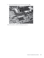
Remove the two Torx 8 screws
 |
View all HP EliteBook 8570w manuals
Add to My Manuals
Save this manual to your list of manuals |
Page 116 highlights
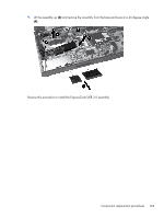
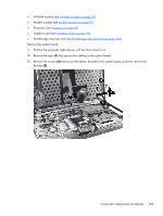
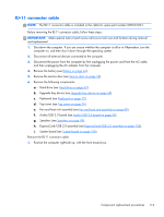
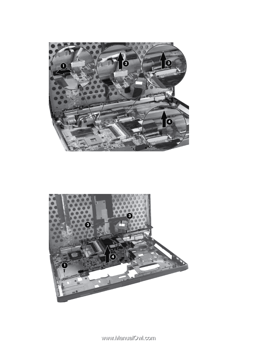
4. Disconnect the power jack (1), the network cable (2), the display cable (3), and the webcam cable (4). 5. Remove the Phillips screw (1) that secures the smart card reader to the system board. 6. Remove the three Torx 8 screws (2) that secure the system board to the base enclosure. 7. Remove the two Torx 8 screws (3) that secure the system board to the optical drive connector. 8. Remove the system board (4) from the base enclosure. 108 Chapter 4 Removal and replacement procedures
-
 1
1 -
2
-
3
-
4
-
5
-
6
-
7
-
8
-
9
-
10
-
11
-
12
-
13
-
14
-
15
-
16
-
17
-
18
-
19
-
20
-
21
-
22
-
23
-
24
-
25
-
26
-
27
-
28
-
29
-
30
-
31
-
32
-
33
-
34
-
35
-
36
-
37
-
38
-
39
-
40
-
41
-
42
-
43
-
44
-
45
-
46
-
47
-
48
-
49
-
50
-
51
-
52
-
53
-
54
-
55
-
56
-
57
-
58
-
59
-
60
-
61
-
62
-
63
-
64
-
65
-
66
-
67
-
68
-
69
-
70
-
71
-
72
-
73
-
74
-
75
-
76
-
77
-
78
-
79
-
80
-
81
-
82
-
83
-
84
-
85
-
86
-
87
-
88
-
89
-
90
-
91
-
92
-
93
-
94
-
95
-
96
-
97
-
98
-
99
-
100
-
101
-
102
-
103
-
104
-
105
-
106
-
107
-
108
-
109
-
110
-
 111
111 -
 112
112 -
 113
113 -
 114
114 -
 115
115 -
 116
116 -
 117
117 -
 118
118 -
 119
119 -
 120
120 -
 121
121 -
122
-
123
-
124
-
125
-
126
-
127
-
128
-
129
-
130
-
131
-
132
-
133
-
134
-
135
-
136
-
137
-
138
-
139
-
140
-
141
-
142
-
143
-
144
-
145
-
146
-
147
-
148
-
149
-
150
-
151
-
152
-
153
-
154
-
155
-
156
-
157
-
158
-
159
-
160
-
161
-
162
-
163
-
164
-
165
-
166
-
167
 |
 |
4.
Disconnect the power jack
(1)
, the network cable
(2)
, the display cable
(3)
, and the webcam
cable
(4)
.
5.
Remove the Phillips screw
(1)
that secures the smart card reader to the system board.
6.
Remove the three Torx 8 screws
(2)
that secure the system board to the base enclosure.
7.
Remove the two Torx 8 screws
(3)
that secure the system board to the optical drive connector.
8.
Remove the system board
(4)
from the base enclosure.
108
Chapter 4
Removal and replacement procedures