HP Evo n1020v Maintenance and Service Guide
HP Evo n1020v - Notebook PC Manual
 |
View all HP Evo n1020v manuals
Add to My Manuals
Save this manual to your list of manuals |
HP Evo n1020v manual content summary:
- HP Evo n1020v | Maintenance and Service Guide - Page 1
Series Compaq Presario 1500 Series Mobile PC Document Part Number: 279372-002 November 2002 This guide is a troubleshooting reference used for maintaining and servicing the notebook. It provides comprehensive information on identifying computer features, components, and spare parts, troubleshooting - HP Evo n1020v | Maintenance and Service Guide - Page 2
, L.P. Compaq, the Compaq logo, Evo, and Presario are trademarks of Compaq Information Technologies herein may be trademarks of their respective companies. Compaq shall not be liable for technical or editorial to change without notice. The warranties for Compaq products are set forth in the express - HP Evo n1020v | Maintenance and Service Guide - Page 3
1.1 Models 1-2 1.2 Features 1-27 1.3 Clearing a Password 1-29 1.4 Power Management 1-30 1.5 Computer External Components 1-31 1.6 Design Overview 1-41 2 Troubleshooting 2.1 Computer Setup and Diagnostics Utilities 2-1 Selecting Computer Setup or Compaq Diagnostics 2-1 Selecting from the File - HP Evo n1020v | Maintenance and Service Guide - Page 4
Board 5-13 5.6 Mini PCI Communications Board 5-15 5.7 Disk Cell RTC Battery 5-18 5.8 Connector Cover 5-19 5.9 LED Cover 5-20 5.10 Keyboard 5-22 5.11 Heat Spreader 5-25 5.12 Processor 5-28 5.13 Display 5-30 5.14 Palm Rest 5-35 5.15 Diskette Drive 5-39 iv Maintenance and Service Guide - HP Evo n1020v | Maintenance and Service Guide - Page 5
Cover 5-50 5.21 Fan 5-54 5.22 System Board 5-56 5.23 Modem Cable 5-60 6 Specifications A Connector Pin Assignments B Screw Listing C Power Cord Set Requirements 3-Conductor Power Cord Set B-1 General Requirements B-1 Country-Specific Requirements B-2 Index Maintenance and Service Guide v - HP Evo n1020v | Maintenance and Service Guide - Page 6
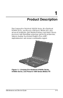
processors with SpeedStep technology and 64-bit architecture, industry-leading Accelerated Graphics Port (AGP) implementation, and extensive multimedia support. Figure 1-1. Compaq Evo Notebook N1020v Series, N1000v Series, and Presario 1500 Series Mobile PC Maintenance and Service Guide 1-1 - HP Evo n1020v | Maintenance and Service Guide - Page 7
Table 1-1 Compaq Evo Notebook N1020v, N1000v, and Presario 1500 Model Naming Conventions Key N1020v P 220 P5 40 V C 51 O XXXXXX-XXX 1 2 3 4 567 8 9 10 Key Description Options 1 Brand/Series designator N = Evo Notebook P = Presario 1020 = 1020 Series 1000 = 1000 Series 1500 = 1500 Series - HP Evo n1020v | Maintenance and Service Guide - Page 8
Compaq Evo Notebook N1020v Models The following Evo Notebook N1020v models use config. code LDMZ and feature: ■ TouchPad pointing device ■ 8-cell, 4.4-Ah lithium ion (Li ion) battery pack ■ 2-year warranty ■ diskette drive C 150 X4 20 V C 25 O Germany 470050-730 Maintenance and Service Guide 1-3 - HP Evo n1020v | Maintenance and Service Guide - Page 9
Compaq Evo Notebook N1020v Models (Continued) The following Evo Notebook N1020v models use config. code LDLZ and feature: ■ TouchPad pointing device ■ 8-cell, 4.4-Ah lithium ion (Li ion) battery pack ■ 1-year warranty ■ diskette drive -687 470045-690 470045-691 1-4 Maintenance and Service Guide - HP Evo n1020v | Maintenance and Service Guide - Page 10
Product Description Table 1-2 Compaq Evo Notebook N1020v Models (Continued) N1020v P 240 X5 40 W C 25 O Asia/Pacific Australia Belgium Brazil Czech Republic Brazil Latin America 470050-117 470050-102 Latin America (NAFTA) United States 470050-114 470051-359 Maintenance and Service Guide 1-5 - HP Evo n1020v | Maintenance and Service Guide - Page 11
Product Description Table 1-2 Compaq Evo Notebook N1020v Models (Continued) N1020v P 200 X5 30 W C 25 O Brazil Latin America 470050-118 470050-104 Latin America (NAFTA) United -056 470050-088 470050-091 470050-092 470050-095 470050-096 470050-099 470045-647 1-6 Maintenance and Service Guide - HP Evo n1020v | Maintenance and Service Guide - Page 12
Product Description Table 1-2 Compaq Evo Notebook N1020v Models (Continued) N1020v P 200 X4 20 V C 25 O Asia/Pacific Australia Hong Kong India Korea 470051-324 X4 40 W C 40 O Asia/Pacific Australia 470051-326 Korea 470051-313 Taiwan 470051-341 470051-333 Maintenance and Service Guide 1-7 - HP Evo n1020v | Maintenance and Service Guide - Page 13
Product Description Table 1-2 Compaq Evo Notebook N1020v Models (Continued) N1020v P 180 X4 30 W C 25 O Brazil Latin America Latin America (NAFTA) 470050- O Brazil Latin America 470050-121 470050-107 Latin America (NAFTA) United States 470050-108 470051-363 1-8 Maintenance and Service Guide - HP Evo n1020v | Maintenance and Service Guide - Page 14
Product Description Table 1-2 Compaq Evo Notebook N1020v Models (Continued) N1020v C 160 X4 20 D C 25 E French Canada Japan 470045-651 Japan English 470047-933 United States 470049-786 470049-665 470049-787 470049-790 470049-791 470049-794 470049-795 470049-799 Maintenance and Service Guide 1-9 - HP Evo n1020v | Maintenance and Service Guide - Page 15
1-3 Compaq Evo Notebook N1000v Models The following Evo Notebook N1000v models use config. code KQDZ and feature: ■ Dual Stick pointing device (TouchPad and pointing stick) ■ 8-cell, 4.0-Ah lithium ion (Li ion) battery pack ■ 3-year warranty ■ diskette drive ■ 32 MB of discrete video memory N1000v - HP Evo n1020v | Maintenance and Service Guide - Page 16
Product Description Table 1-3 Compaq Evo Notebook N1000v Models (Continued) The following Evo Notebook N1000v models use config. code KT2Z and feature: ■ TouchPad pointing device ■ 8-cell, 4.0-Ah Li ion battery pack ■ 2-year warranty ■ diskette drive ■ 32 MB of discrete video memory N1000v P 220 - HP Evo n1020v | Maintenance and Service Guide - Page 17
Compaq Evo Notebook N1000v Models (Continued) The following Evo Notebook N1000v models use config. code KQFZ and feature: ■ TouchPad ■ 8-cell, 4.0-Ah Li ion battery pack ■ 1-year warranty ■ diskette drive ■ 32 MB of discrete video memory 25 O Taiwan 470038-800 1-12 Maintenance and Service Guide - HP Evo n1020v | Maintenance and Service Guide - Page 18
Product Description Table 1-3 Compaq Evo Notebook N1000v Models (Continued) N1000v P 220 P5 30 V C 25 2 Taiwan 470038-801 N1000v P 220 X5 30 W C 25 O Latin America N1000v P 200 X5 20 D C 12 2 Japan Japan (English) 470036-637 Taiwan 470036-640 470038-783 Maintenance and Service Guide 1-13 - HP Evo n1020v | Maintenance and Service Guide - Page 19
Product Description Table 1-3 Compaq Evo Notebook N1000v Models (Continued) N1000v P 200 X4 30 W C 25 O Brazil Latin America 470038-304 470038-299 Latin America (NAFTA) United -753 470036-754 470036-761 470038-803 470037-836 470036-762 470036-769 470036-628 1-14 Maintenance and Service Guide - HP Evo n1020v | Maintenance and Service Guide - Page 20
Product Description Table 1-3 Compaq Evo Notebook N1000v Models (Continued) N1000v P 200 X4 20 V C 25 2 Belgium Czech Republic Denmark France French Canada Greece/Poland 470037-787 470037-830 Norway Thailand United States 470037-809 470037-826 470037-785 Maintenance and Service Guide 1-15 - HP Evo n1020v | Maintenance and Service Guide - Page 21
12 E United States (NAFTA) 470040-456 Table 1-4 Compaq Presario 1500 Models The following Presario 1500 notebook models use config. code LDLZ and feature: ■ TouchPad ■ 8-cell, 4.0-Ah Li ion battery pack ■ 2-year warranty ■ diskette drive ■ 32 MB of discrete video memory P1527 P 240 X5 30 W C 51 - HP Evo n1020v | Maintenance and Service Guide - Page 22
1-4 Compaq Presario 1500 Models (Continued) P1522 P 200 X4 30 W C 25 E Belgium 470046-243 The following Presario 1500 notebook models use config. code KT2Z and feature: ■ TouchPad ■ 8-cell, 4.0-Ah Li ion battery pack ■ 2-year warranty ■ diskette drive ■ 32 MB of discrete video memory P1515 - HP Evo n1020v | Maintenance and Service Guide - Page 23
Compaq Presario 1500 Models (Continued) The following Presario 1500 notebook models use config. code LDLZ and feature: ■ TouchPad ■ 8-cell, 4.0-Ah Li ion battery pack ■ 1-year warranty ■ diskette drive ■ 32 MB of discrete video memory 470050-053 470047-704 1-18 Maintenance and Service Guide - HP Evo n1020v | Maintenance and Service Guide - Page 24
Product Description Table 1-4 Compaq Presario 1500 Models (Continued) P1525 P 240 X5 30 W C 25 E Czech Republic Denmark European International France Greece/Poland P 240 X5 20 V C 25 E Korea 470045-729 P1572 P 240 X4 40 W C 25 E Hong Kong 470050-700 Maintenance and Service Guide 1-19 - HP Evo n1020v | Maintenance and Service Guide - Page 25
Product Description Table 1-4 Compaq Presario 1500 Models (Continued) P1520 P 240 X4 40 W C 25 E Latin America 470045-422 Latin America (NAFTA) 470045-429 P1508 P Australia 470045-731 P1565 P 240 X4 20 V C 25 E Hong Kong 470048-578 Korea 470050-055 1-20 Maintenance and Service Guide - HP Evo n1020v | Maintenance and Service Guide - Page 26
Product Description Table 1-4 Compaq Presario 1500 Models (Continued) P1509 P 240 X4 20 D C 25 E Asia Pacific 470045-721 Thailand 470045-722 P1512 P 240 X4 20 E Asia Pacific 470041-812 Australia 470041-811 P1536 P 200 X4 20 V C 25 E Taiwan 470050-705 Maintenance and Service Guide 1-21 - HP Evo n1020v | Maintenance and Service Guide - Page 27
Product Description Table 1-4 Compaq Presario 1500 Models (Continued) P1506 P 200 X4 20 V C 25 E Hong Kong 470045-735 P1540 P 200 X4 20 R C 25 E Asia Pacific C 25 E Hong Kong 470040-458 P1522 C 170 X4 20 D C 25 E People's Republic of China 470050-706 1-22 Maintenance and Service Guide - HP Evo n1020v | Maintenance and Service Guide - Page 28
model The following Presario 1500 notebook model uses config. code KQF2 and features: ■ TouchPad ■ 8-cell, 4.0-Ah Li ion battery pack ■ 1-year warranty ■ diskette drive ■ 32 MB of discrete video memory P1501 P 160 P5 30 W C 25 E United States 470037-317 Maintenance and Service Guide 1-23 - HP Evo n1020v | Maintenance and Service Guide - Page 29
Compaq Presario 1500 Models (Continued) The following Presario 1500 notebook model uses config. code KQF3 and features: ■ TouchPad ■ 8-cell, 4.0-Ah Li ion battery pack ■ 1-year warranty ■ diskette drive ■ 32 MB of discrete video memory America (NAFTA) 470036-799 1-24 Maintenance and Service Guide - HP Evo n1020v | Maintenance and Service Guide - Page 30
Product Description Table 1-4 Compaq Presario 1500 Models (Continued) P1500 P 220 X5 30 W C 25 E Asia Pacific Australia 470036-808 Korea 470036-800 Thailand 470036- 470036-601 Latin America (NAFTA) 470036-602 P1500 P 200 X4 20 W C 25 E Taiwan 470038-812 Maintenance and Service Guide 1-25 - HP Evo n1020v | Maintenance and Service Guide - Page 31
Table 1-4 Compaq Presario 1500 Models ( notebook model: ❏ The Evo Notebook N1020v features an Intel Mobile Pentium 4 2.4-, 2.0-, or 1.8-GHz processor with 512-KB integrated L2 cache, or an Intel Celeron 1.6- or 1.5-GHz processor with 256-KB integrated L2 cache. 1-26 Maintenance and Service Guide - HP Evo n1020v | Maintenance and Service Guide - Page 32
through MultiPort ■ Support for one Type I or II PC Card slot with support for both 32-bit CardBus and 16-bit PC Cards ■ External 65 W AC adapter with power cord ■ 8-cell Li ion battery pack ■ 40-, 30-, or 20-GB high-capacity hard drive, varying by computer model Maintenance and Service Guide 1-27 - HP Evo n1020v | Maintenance and Service Guide - Page 33
■ Support for the following drives through the fixed optical drive: ❏ 24X Max CD-ROM drive ❏ 16X Max CD-RW drive ❏ 8X Max DVD-ROM drive ❏ 8X Max DVD-ROM/CD-RW combination drive ■ Connectors for: ❏ RJ-45 network ❏ RJ-11 modem ❏ Universal serial bus ❏ Parallel devices ❏ External monitor ❏ AC power - HP Evo n1020v | Maintenance and Service Guide - Page 34
If the notebook you are servicing has an unknown password, follow these steps to clear the password. These steps also clear CMOS: 1. Prepare the computer for disassembly (refer to Section 5.3, "Preparing the Computer for Disassembly," for more information). 2. Remove the RTC battery (refer to - HP Evo n1020v | Maintenance and Service Guide - Page 35
1-2. Front and Right Side Components Table 1-5 Front and Right Side Components Item 1 2 Component Stereo speakers (2) Power/Standby light Function Produce stereo sound. On: Power is turned on. Off: Power is turned off. Blinking: Computer is in Standby mode. 1-30 Maintenance and Service Guide - HP Evo n1020v | Maintenance and Service Guide - Page 36
the computer. On: A battery pack is charging. Blinking: A battery pack that is the only available power source has reached a low-battery condition. Accepts an 8-cell Li ion battery pack. Accepts a CD-ROM, CD-RW, DVD-ROM, or DVD/CD-RW combination drive. Provides wireless communication between the - HP Evo n1020v | Maintenance and Service Guide - Page 37
1 Mono microphone jack 2 Stereo speaker/ headphone jack 3 DC power jack Function Connects a mono microphone, disabling the built-in microphone one of the following: ■ AC adapter ■ Optional automobile power adapter/charger ■ Optional aircraft power adapter 1-32 Maintenance and Service Guide - HP Evo n1020v | Maintenance and Service Guide - Page 38
with internal modem models. Security cable slot Attaches an optional security cable to the computer. PC Card eject button Ejects a PC Card from the PC Card slot. PC Card slot Supports a 32-bit (CardBus) or 16-bit PC Card. Diskette drive Accepts diskettes. Maintenance and Service Guide 1-33 - HP Evo n1020v | Maintenance and Service Guide - Page 39
Function Perform preset functions. Turns on the numeric lock function. On: Num lock is on and the embedded numeric keypad is enabled. 1-34 Maintenance and Service Guide - HP Evo n1020v | Maintenance and Service Guide - Page 40
keypad. Move the cursor around the screen. Displays a menu when using a Microsoft application. The menu is the same one that is displayed by pressing the right mouse button. Display the Windows Start menu. Used with hotkeys to perform preset hotkey functions. Maintenance and Service Guide 1-35 - HP Evo n1020v | Maintenance and Service Guide - Page 41
is the only available power source reaches a low-battery condition. On: Num lock is on and the embedded numeric keypad is enabled. Provide quick access to the Internet. Refer to the Hardware Guide that ships with the computer for information about these buttons. 1-36 Maintenance and Service Guide - HP Evo n1020v | Maintenance and Service Guide - Page 42
(Continued) Item Component 4 Power button 5 Digital audio button 6 Volume control buttons 7 Caps lock light 8 Drive indicator light 9 Display lid switch 10 Microphone 11 TouchPad 12 TouchPad buttons 13 EasyScroll 14 Battery power light 15 Power/Standby light Function Turns on - HP Evo n1020v | Maintenance and Service Guide - Page 43
Table 1-9. Figure 1-6. Bottom Components Table 1-9 Bottom Components Item 1 Component Connector cover 2 Docking connector Function Protects the parallel, external monitor, external keyboard/mouse, and USB connectors. Connects the computer to an optional port replicator. 1-38 Maintenance and - HP Evo n1020v | Maintenance and Service Guide - Page 44
computer; needed when you call Compaq customer support. Releases the battery pack from the battery compartment. Accepts an 8-cell Li ion battery pack. Covers the memory expansion compartment that contains two memory expansion slots for memory expansion boards. Maintenance and Service Guide 1-39 - HP Evo n1020v | Maintenance and Service Guide - Page 45
. Refer to Chapter 3, "Illustrated Parts Catalog," to identify replacement parts and Chapter 5, "Removal and Replacement Procedures," for disassembly steps. The system board provides the following device connections: ■ Memory expansion board ■ Hard drive ■ Display ■ Keyboard/TouchPad or pointing - HP Evo n1020v | Maintenance and Service Guide - Page 46
Å WARNING: Only authorized technicians trained by Compaq should repair this equipment. All troubleshooting and repair procedures are detailed to allow only subassembly/module level repair. Because of the complexity of the individual boards and subassemblies, no one should - HP Evo n1020v | Maintenance and Service Guide - Page 47
Troubleshooting ■ Compaq Diagnostics-A system information and diagnostic utility that is used within your Windows operating system. Use this utility whenever possible to: ❏ Display system information. ❏ Test system components. ❏ Troubleshoot a device configuration problem and Service Guide - HP Evo n1020v | Maintenance and Service Guide - Page 48
battery packs in the system. ■ View specification information about the processor, memory and cache size, and system ROM. Save system configuration settings to a diskette. Restore system configuration settings from a diskette. Replace exit and restart the computer. Maintenance and Service Guide 2-3 - HP Evo n1020v | Maintenance and Service Guide - Page 49
Troubleshooting Selecting from the Security Menu Table 2-2 Security Menu Select To Do This Setup Password Enter, change, or delete a setup password. (The setup password is called an administrator password in Compaq Computer Security, a program accessed from the Windows Control Panel.) Power- - HP Evo n1020v | Maintenance and Service Guide - Page 50
system is not loaded.) ■ Set an optional external monitor or overhead projector connected to a video card in a docking base as the primary device. (When the computer display is set as secondary, the computer must be shut down before undocking from a docking base.) Maintenance and Service Guide 2-5 - HP Evo n1020v | Maintenance and Service Guide - Page 51
processor serial number by the processor to the software. HDD Self Test Options Run a quick comprehensive self test on hard drives in the system that support the test features. * Video modes vary even within regions. However, NTSC is common in North America; PAL, in Europe, Africa, and the Middle - HP Evo n1020v | Maintenance and Service Guide - Page 52
Troubleshooting 2.2 Using Compaq Diagnostics When you access Compaq Diagnostics, a scan of all system components is displayed on the screen before the Compaq Diagnostics window opens. You can display more or less information from anywhere within Compaq Diagnostics by selecting Level on the menu bar. - HP Evo n1020v | Maintenance and Service Guide - Page 53
Troubleshooting Obtaining, Saving, or Printing Diagnostic Test Information 1. Access Compaq Diagnostics by selecting Start > Settings > Control Panel > Compaq Diagnostics. 2. Select the Test tab. 3. In the scroll box, select the category or device you want to test. 4. Select a test type: ❏ Quick - HP Evo n1020v | Maintenance and Service Guide - Page 54
Troubleshooting 5. Select a test mode: ❏ Interactive Mode-Provides maximum control over the testing process. You determine whether the test was passed or failed, and you may be prompted to insert or remove devices. ❏ Unattended Mode-Does not display prompts. If errors are found, they are displayed - HP Evo n1020v | Maintenance and Service Guide - Page 55
Troubleshooting No Power, Part 1 No Power, Part 2 No Power, Part 3 No Power, Part 4 No Video, Part 1 No Video, Part 2 Nonfunctioning Docking Station No Operating System (OS) Loading No OS Loading From Hard Drive, Part 1 No OS Loading From Hard Drive, Part 2 No OS Loading From Hard Drive, Part - HP Evo n1020v | Maintenance and Service Guide - Page 56
Troubleshooting Begin troubleshooting. N Is there power? Y Go to Flowchart 2.2, No Power, Part 1. N Beeps, LEDs, or error messages? Y Check LED board, speaker connections. N Is there video? (no boot) Y Go to Flowchart 2.6, No Video, Part Connection. End Maintenance and Service Guide 2-11 - HP Evo n1020v | Maintenance and Service Guide - Page 57
Troubleshooting Flowchart 2.2 - No Power, Part 1 No power (power LED is off). Remove from docking station (if applicable). N Power up on battery power? Y N Power up on AC power? Y Y Power up in docking station? N *Reset power. *Reset power. N Power up on battery power? Y N Power up on AC power? - HP Evo n1020v | Maintenance and Service Guide - Page 58
in battery socket and clean if necessary. Y Power on? N Done Check battery by recharging, moving it to another computer, or replacing it. N Power on? Y Replace power supply (if applicable). N Done Power on? Y Go to Flowchart 2.4, No Power, Part 3. Done Maintenance and Service Guide 2-13 - HP Evo n1020v | Maintenance and Service Guide - Page 59
. Y Power on? N N Power outlet active? Y Replace power cord. Y Power on? N Done Done Try different outlet. External Internal or external AC adapter? Replace external AC adapter. Internal Go to Flowchart 2.5, No Power, Part 4. N Power on? Y Done Done 2-14 Maintenance and Service Guide - HP Evo n1020v | Maintenance and Service Guide - Page 60
Y Done Replace the following items (if applicable). Check computer operation after each replacement: 1. Internal DC-DC converter* 2. Internal AC adapter 3. Processor board* 4. System board* *Replace these items as a set to prevent shorting out among components. Maintenance and Service Guide 2-15 - HP Evo n1020v | Maintenance and Service Guide - Page 61
after each replacement. 1. Cable between notebook and computer display (if applicable) 2. Inverter board (if applicable) 3. Display 4. System board N N Video OK? Try another display. Internal and external video OK? Replace system board. Y Y Done Done 2-16 Maintenance and Service Guide - HP Evo n1020v | Maintenance and Service Guide - Page 62
Troubleshooting Flowchart 2.7 - No Video, Part 2 Continued from Flowchart 2.6, No Video, Part 1. Remove notebook from docking station, if connected. Adjust display brightness. Check brightness of external monitor. N Video OK? Y Go to "A" in Flowchart 2.6, No Video, Part 1. Y Video OK? N - HP Evo n1020v | Maintenance and Service Guide - Page 63
) Nonfunctioning docking station. Reseat power cord in docking station and power outlet. Check voltage setting on docking station. Reset monitor cable connector at docking station. Y Docking station operating? N Remove notebook, reseat all internal parts, and replace any damaged items in docking - HP Evo n1020v | Maintenance and Service Guide - Page 64
hard drive, go to Flowchart 2.10, No OS Loading from Hard Drive, Part 1. No OS loading from diskette drive, go to Flowchart 2.13, No OS Loading from Diskette Drive. No OS loading from CD- or DVD-ROM drive, go to Flowchart 2.14, No OS Loading from CD- or DVD-ROM Drive. Maintenance and Service Guide - HP Evo n1020v | Maintenance and Service Guide - Page 65
Troubleshooting Flowchart 2.10 - No OS Loading from Hard Drive, Part 1 OS not loading from hard drive. Y Nonsystem disk message? N Go to Flowchart 2.11, No OS Loading from Hard Drive, Part 2. Reseat external hard drive. Y OS loading? N N Boot from CD? Y Check the setup utility for correct - HP Evo n1020v | Maintenance and Service Guide - Page 66
, then format hard drive to bootable C:\ prompt. Hard drive formatted? Y Format hard drive and bring to a bootable C:\ Y prompt. Computer booted? N Go to Flowchart 2.12, No OS Loading from Hard Drive, Part 3. Load OS using Restore CD (if applicable). Maintenance and Service Guide 2-21 - HP Evo n1020v | Maintenance and Service Guide - Page 67
sectors be fixed? Y Clean virus. Y OS loading from hard drive? N Y Diagnostics on diskette? N Replace hard drive. Run diagnostics and follow recommendations. N Fix bad sectors. Boot from hard drive? Replace hard drive. Y Done Replace hard drive. Done 2-22 Maintenance and Service Guide - HP Evo n1020v | Maintenance and Service Guide - Page 68
. Refer to Section 1.3, "Clearing a Password," for instructions. N Bootable diskette in drive? Install bootable diskette and reboot computer. Y Check diskette for system files. Try different diskette. Y Nonsystem disk error? N 1. Replace diskette drive. 2. Replace system board. Y OS loading - HP Evo n1020v | Maintenance and Service Guide - Page 69
disc. Y Boots from CD or DVD? N Done Y Reseat drive. Boots from CD or DVD? N N Booting from another device? Y Y Booting order correct? N Done Go to Flowchart 2.17, Nonfunctioning Device. Clear CMOS. Refer to Section 1.3, "Clearing a Password," for instructions. Correct boot order using the - HP Evo n1020v | Maintenance and Service Guide - Page 70
Y No audio. Turn up audio internally or externally. Audio? Done N Y Notebook in docking station (if applicable)? N Undock N Internal audio? Go to Flowchart 2.16, No Audio, Part 2. Y Go to Flowchart 2.16, No Audio, Part 2. Replace the following docking station components one at a time as - HP Evo n1020v | Maintenance and Service Guide - Page 71
Flowchart 2.15, No Audio, Part 1. N Audio driver in OS configured? Y Reload audio drivers. N Correct drivers for application? Y Load drivers and set configuration in OS. Connect to external speaker. N Audio? Y Replace audio board and speaker connections in notebook (if applicable). Y Audio - HP Evo n1020v | Maintenance and Service Guide - Page 72
damage. Y Any physical device detected? N Fix or replace broken item. Reattach device. Close notebook, plug in power, and reboot. N Device boots properly? Y Possible bad hard drive. Replace drive. Possible bad NIC. Replace card. If integrated NIC, replace system board. Go to Flowchart 2.9, No OS - HP Evo n1020v | Maintenance and Service Guide - Page 73
operating properly. Connect notebook to good external keyboard. N External device works? Y Replace system board. Reseat internal keyboard connector (if applicable). N OK? Y Replace internal keyboard or cable. Y Done OK? N Replace system board. Done 2-28 Maintenance and Service Guide - HP Evo n1020v | Maintenance and Service Guide - Page 74
Connect notebook to good external pointing device. N External device works? Y Replace system board. Reseat internal pointing device connector (if applicable). N OK? Y Replace internal pointing device or cable. Y Done OK? N Replace system board. Done Maintenance and Service Guide 2-29 - HP Evo n1020v | Maintenance and Service Guide - Page 75
to nondigital line. N N NIC/modem configured in OS? Reload drivers and reconfigure. Y N Y OK? Done Disconnect all power from the notebook and open. Reseat NIC/modem (if applicable). Replace NIC/modem (if applicable). Y OK? N Done Replace system board. 2-30 Maintenance and Service Guide - HP Evo n1020v | Maintenance and Service Guide - Page 76
for spare part numbers and option part numbers. 3.1 Serial Number Location When ordering parts or requesting information, provide the computer serial number and model number located on the bottom of the computer (Figure 3-1). Figure 3-1. Serial Number Location Maintenance and Service Guide 3-1 - HP Evo n1020v | Maintenance and Service Guide - Page 77
Illustrated Parts Catalog 3.2 Computer System Major Components Figure 3-2. Computer System Major Components 3-2 Maintenance and Service Guide - HP Evo n1020v | Maintenance and Service Guide - Page 78
310688-001 310687-001 Parts have silver finish for use with Presario 1500 models with config. codes beginning with "K" 15-inch, TFT, SXGA+ 15-inch, TFT, XGA 14-inch, TFT, XGA 286754-001 285521-001 285520-001 Display inverter board (not illustrated) 293348-001 Maintenance and Service Guide 3-3 - HP Evo n1020v | Maintenance and Service Guide - Page 79
Illustrated Parts Catalog Figure 3-2. Computer System Major Components 3-4 Maintenance and Service Guide - HP Evo n1020v | Maintenance and Service Guide - Page 80
saver *Connector cover *Hard drive bracket *Mini PCI compartment cover *Memory expansion compartment cover *Battery bezel *Includes two of each part, one with carbon finish for use with Evo Notebook N1020v and N1000v models and one with silver finish for use with Presario 1500 models Not illustrated - HP Evo n1020v | Maintenance and Service Guide - Page 81
Illustrated Parts Catalog Figure 3-2. Computer System Major Components 3-6 Maintenance and Service Guide - HP Evo n1020v | Maintenance and Service Guide - Page 82
: Computer System Major Components (Continued) Item 4 Description Spare Part Number Keyboards (for use only with TouchPad notebook models) Arabic Belgian Brazilian Chinese Czech Danish French French -111 285531-AB1 285531-281 285531-141 285531-031 285531-001 Maintenance and Service Guide 3-7 - HP Evo n1020v | Maintenance and Service Guide - Page 83
Illustrated Parts Catalog Figure 3-2. Computer System Major Components 3-8 Maintenance and Service Guide - HP Evo n1020v | Maintenance and Service Guide - Page 84
a diskette drive 310692-001 310693-001 Parts have silver finish for use with Presario 1500 models with config. codes beginning with "K" for use only with models with a diskette drive for use only with models without a diskette drive 285533-001 285534-001 Maintenance and Service Guide 3-9 - HP Evo n1020v | Maintenance and Service Guide - Page 85
Illustrated Parts Catalog Figure 3-2. Computer System Major Components 3-10 Maintenance and Service Guide - HP Evo n1020v | Maintenance and Service Guide - Page 86
stick cable connector (for use only on Dual Stick notebook models) Pointing stick board (for use only on Dual Stick notebook models) Heat spreaders For use only on Evo Notebook N1020v and N1000v models For use only on Presario 1500 models 291648-001 285544-001 Maintenance and Service Guide 3-11 - HP Evo n1020v | Maintenance and Service Guide - Page 87
Illustrated Parts Catalog Figure 3-2. Computer System Major Components 3-12 Maintenance and Service Guide - HP Evo n1020v | Maintenance and Service Guide - Page 88
Illustrated Parts Catalog Table 3-1 Spare Parts: Computer System Major Components (Continued) Item 11 12 13 14 processor 1.3 V Intel Celeron 1.4-GHz processor 1.3 V Charger board Speaker assembly Fan Spare Part Number 310306-001 286753-001 311385-001 286752-001 312536-001 311284-001 286751- - HP Evo n1020v | Maintenance and Service Guide - Page 89
Illustrated Parts Catalog Figure 3-2. Computer System Major Components 3-14 Maintenance and Service Guide - HP Evo n1020v | Maintenance and Service Guide - Page 90
"L" Parts have silver finish for use with Presario 1500 models with config. codes beginning with "K" Hard drives 60 GB 40 GB 30 GB 20 GB Spare Part Number 311282-001 285515-001 311292-001 291644-001 311291-001 285532-001 303527-001 273491-001 192406-001 288291-001 Maintenance and Service Guide - HP Evo n1020v | Maintenance and Service Guide - Page 91
Illustrated Parts Catalog Figure 3-2. Computer System Major Components 3-16 Maintenance and Service Guide - HP Evo n1020v | Maintenance and Service Guide - Page 92
, Li ion Memory expansion boards 512 MB 256 MB 128 MB Battery packs 8 cell, 62 Wh, 4.0 Ah, Li ion 8 cell, 58 Wh, 3.6 Ah, Li ion Optical drives for use only with Evo Notebook N1020v models and Presario 1500 models with config. codes beginning with "L" 24X Max CD-ROM drive 8X Max DVD-ROM drive 24X Max - HP Evo n1020v | Maintenance and Service Guide - Page 93
Illustrated Parts Catalog 3.3 Miscellaneous Plastics/Hardware Kit Figure 3-3. Miscellaneous Plastics/Hardware Kit Components 3-18 Maintenance and Service Guide - HP Evo n1020v | Maintenance and Service Guide - Page 94
drive rear alignment rail 13 *Battery bezel 7 Optical drive front alignment rail 14 Computer feet *Includes two of each part, one with carbon finish for use with Evo Notebook N1020v and N1000v models and one with silver finish for use with Presario 1500 models Maintenance and Service Guide - HP Evo n1020v | Maintenance and Service Guide - Page 95
Illustrated Parts Catalog 3.4 Miscellaneous Cable Kit Figure 3-4. Miscellaneous Cable Kit Components 3-20 Maintenance and Service Guide - HP Evo n1020v | Maintenance and Service Guide - Page 96
Cable Kit Components Spare Part Number 285540-001 Item 1 2 3 4 5 6 7 Description Diskette drive cable TouchButton board-to-TouchPad cable TouchButton board-to-system board cable Microphone TouchButton board-to-pointing stick board cable (for use only with Dual Stick notebook models) Keyboard-to - HP Evo n1020v | Maintenance and Service Guide - Page 97
Illustrated Parts Catalog 3.5 Mass Storage Devices Figure 3-5. Mass Storage Devices 3-22 Maintenance and Service Guide - HP Evo n1020v | Maintenance and Service Guide - Page 98
with Evo Notebook N1000v models and Presario 1500 models with config. codes beginning with "K" 24X Max CD-ROM drive 8X Max DVD-ROM drive 24X Max DVD-ROM/CD-RW combination drive 8X Max DVD-ROM/CD-RW combination drive 285526-001 285527-001 304691-001 285529-001 Maintenance and Service Guide 3-23 - HP Evo n1020v | Maintenance and Service Guide - Page 99
Catalog 3.6 Miscellaneous Table 3-5 Spare Parts: Miscellaneous (not illustrated) Description Spare Part Number Logo Kit 285547-001 Screw Kit, includes the following screws (Refer to Appendix C, "Screw Listing," for more information on screw specifications and usage.) 285542-001 ■ Torx T8 - HP Evo n1020v | Maintenance and Service Guide - Page 100
service. 4.1 Tools Required You will need the following tools to complete the removal and replacement procedures: ■ Magnetic screwdriver ■ Phillips P0 screwdriver ■ Torx T8 screwdriver ■ Tool kit (includes connector removal tool, loopback plugs, and case utility tool) Maintenance and Service Guide - HP Evo n1020v | Maintenance and Service Guide - Page 101
a way that they cannot be caught or snagged by parts being removed or replaced. Handle flex cables with extreme care; these cables tear easily. Ä CAUTION: When servicing the computer, ensure that cables are placed in their proper locations during the reassembly process. Improper cable placement can - HP Evo n1020v | Maintenance and Service Guide - Page 102
, such as monitors or speakers. ■ Avoid exposing a drive to temperature extremes or to liquids. ■ If a drive must be mailed, place the drive in a bubble-pack mailer or other suitable form of protective packaging and label the package "Fragile: Handle With Care." Maintenance and Service Guide 4-3 - HP Evo n1020v | Maintenance and Service Guide - Page 103
Replacement enough power to parts in their containers until the parts arrive at static-free workstations. ■ Place items on a grounded surface before removing items from their containers. ■ Always be properly grounded when touching a sensitive component or assembly. 4-4 Maintenance and Service Guide - HP Evo n1020v | Maintenance and Service Guide - Page 104
components, parts, and assemblies by the case or PCM laminate. Handle these items only at static-free workstations. ■ Avoid contact with pins, leads, or circuitry. ■ Turn off power and input signals before inserting or removing connectors or test equipment. Maintenance and Service Guide 4-5 - HP Evo n1020v | Maintenance and Service Guide - Page 105
Removal and Replacement Preliminaries 4.7 Grounding Equipment and Methods Grounding equipment must include either a wrist strap megohm resistance ■ Static-dissipative tables or floor mats with hard ties to the ground ■ Field service kits ■ Static awareness labels ■ Material-handling packages 4-6 - HP Evo n1020v | Maintenance and Service Guide - Page 106
Removal and Replacement Preliminaries ■ Nonconductive plastic bags, tubes, or boxes ■ Metal tote boxes ■ Electrostatic voltage levels and protective materials Metallized laminate Use Bags Floor mats Floor mats Voltage Protection Level 1,500 V 7,500 V 5,000 V Maintenance and Service Guide 4-7 - HP Evo n1020v | Maintenance and Service Guide - Page 107
different sizes, that must be removed and replaced when servicing the computer. Make special note of each screw size and location during removal and replacement. Refer to Appendix C, "Screw Listing," for detailed information on screw sizes, locations, and usage. Maintenance and Service Guide 5-1 - HP Evo n1020v | Maintenance and Service Guide - Page 108
and Replacement Procedures 5.1 Serial Number Report the computer serial number to Compaq when requesting information or ordering spare parts. The serial number is located on the bottom of the computer as indicated in Figure 5-1. Figure 5-1. Serial Number Location 5-2 Maintenance and Service Guide - HP Evo n1020v | Maintenance and Service Guide - Page 109
computer for disassembly Battery pack Optical drive Hard drive Computer feet Memory expansion board Mini PCI communications board Disk cell RTC battery Connector cover LED cover Keyboard Heat spreader Processor Display Palm rest Diskette drive # of Screws Removed 0 2 1 to remove the hard drive 4 to - HP Evo n1020v | Maintenance and Service Guide - Page 110
of Screws Removed 4 on TouchPad models 5 on Dual Stick models 2 3 0 5 0 7 1 5.3 Preparing the Computer for Disassembly Perform the following steps before disassembling the computer: 1. Turn off the computer. 2. Disconnect the AC adapter and all external devices. 5-4 Maintenance and Service Guide - HP Evo n1020v | Maintenance and Service Guide - Page 111
Removal and Replacement Procedures Battery Packs Spare Part Number Information 8 cell, 62 W hour, 4.0 Ah, Li ion 8 cell, 58 W hour, 3.6 Ah, Li ion 289053-001 281766-001 3. Remove the battery pack by following these steps: a. Turn the computer bottom side up with the left side facing forward. b. - HP Evo n1020v | Maintenance and Service Guide - Page 112
with carbon finish for Evo Notebook N1020v and N1000v models and silver finish for Presario 1500 models, and are included in the Miscellaneous Plastics/Hardware Kit, spare part number 285541-001. Reverse the preceding procedures to install the battery bezel. 5-6 Maintenance and Service Guide - HP Evo n1020v | Maintenance and Service Guide - Page 113
and Replacement Procedures 5. Remove the optical drive by following these steps: Optical Drives Spare Part Number Information For use only with Evo Notebook N1020v models and Presario 1500 models with config. codes beginning with "L" 24X Max CD-ROM drive 8X Max DVD-ROM drive 24X Max DVD-ROM - HP Evo n1020v | Maintenance and Service Guide - Page 114
Removal and Replacement Procedures b. Remove the two TM2.5 × 5.0 screws that secure the optical drive to the base enclosure (Figure 5-4). Figure 5-4. Removing the Optical Drive Screws 5-8 Maintenance and Service Guide - HP Evo n1020v | Maintenance and Service Guide - Page 115
manual release hole on the front bezel of the optical drive 1 (Figure 5-5). Press firmly. e. Grasp the drive bezel and slide the drive out of the optical drive bay 2. Figure 5-5. Removing an Optical Drive Reverse the preceding procedures to install a optical drive. Maintenance and Service Guide - HP Evo n1020v | Maintenance and Service Guide - Page 116
and Replacement Procedures Hard Drives Spare Part Number Information 60 GB 40 GB 30 GB 20 GB 303527-001 273491-001 192406-001 288291-001 6. Remove the hard drive by following these steps: a. Turn the computer bottom side up with the right side facing forward. b. Remove the TM2.5 ×8.0 hard drive - HP Evo n1020v | Maintenance and Service Guide - Page 117
Removal and Replacement Procedures d. Lift the front edge of the hard drive 1 until it rests at an angle (Figure 5-7). e. Remove the hard drive from the hard drive bay 2. Figure 5-7. Removing the Hard Drive Maintenance and Service Guide 5-11 - HP Evo n1020v | Maintenance and Service Guide - Page 118
for Evo Notebook N1020v and N1000v models and silver finish for Presario 1500 models, and are included in the Miscellaneous Plastics/Hardware Kit, spare part number 285541-001. Reverse the preceding procedures to install the hard drive and hard drive bracket. 5-12 Maintenance and Service Guide - HP Evo n1020v | Maintenance and Service Guide - Page 119
5.5 Memory Expansion Board Memory Expansion Boards Spare Part Number Information 512 MB 256 MB 128 MB 285524-001 285523-001 285222-001 1. Prepare the computer for disassembly (Section 5.3). 2. Turn the computer bottom side up with the front facing forward. Maintenance and Service Guide 5-13 - HP Evo n1020v | Maintenance and Service Guide - Page 120
Cover ✎ Memory expansion compartment covers are available with carbon finish for Evo Notebook N1020v and N1000v models and silver finish for Presario 1500 models, and are included in the Miscellaneous Plastics/Hardware Kit, spare part number 285541-001. 5-14 Maintenance and Service Guide - HP Evo n1020v | Maintenance and Service Guide - Page 121
5-11. Removing a Memory Expansion Board Reverse the preceding procedures to install a memory expansion board. 5.6 Mini PCI Communications Board Mini PCI Communication Boards Spare Part Number Information U.S. modem International modem 248776-001 285545-001 Maintenance and Service Guide 5-15 - HP Evo n1020v | Maintenance and Service Guide - Page 122
Slot Cover ✎ Mini PCI compartment covers are available with carbon finish for Evo Notebook N1020v and N1000v models and silver finish for Presario 1500 models, and are included in the Miscellaneous Plastics/Hardware Kit, spare part number 285541-001. 5-16 Maintenance and Service Guide - HP Evo n1020v | Maintenance and Service Guide - Page 123
Removal and Replacement Procedures 7. Disconnect the modem cable from the mini PCI communications board 1 (Figure 5-13). 8. Spread the retaining Removing a Mini PCI Communications Board Reverse the preceding procedures to install a mini PCI communications board. Maintenance and Service Guide 5-17 - HP Evo n1020v | Maintenance and Service Guide - Page 124
Removal and Replacement Procedures 5.7 Disk Cell RTC Battery Disk Cell RTC Battery Spare Part Number Information Disk cell RTC battery 279769-001 1. Prepare the computer for disassembly (Section 5.3). 2. Remove the mini PCI compartment cover (Section 5.6). 3. Remove the RTC battery from its - HP Evo n1020v | Maintenance and Service Guide - Page 125
Replacement Procedures 5.8 Connector Cover ✎ The connector cover is available with carbon finish for Evo Notebook N1020v and N1000v models and silver finish for Presario 1500 models, and are included in the Miscellaneous Plastics/Hardware Kit, spare part cover. Maintenance and Service Guide 5-19 - HP Evo n1020v | Maintenance and Service Guide - Page 126
Removal and Replacement Procedures 5.9 LED Cover LED Cover Spare Part Number Information LED cover for use only with Evo Notebook N1020v models and Presario 1500 models with config. codes beginning with "L" for use only with Evo Notebook N1000v models and Presario 1500 models with config. codes - HP Evo n1020v | Maintenance and Service Guide - Page 127
Removal and Replacement Procedures 4. Turn the computer top side up with the front facing forward. 5. Open the computer. 6. Press down and hold the F1 the LED cover 3. Figure 5-17. Removing the LED Cover Reverse the preceding procedures to install the LED cover. Maintenance and Service Guide 5-21 - HP Evo n1020v | Maintenance and Service Guide - Page 128
Removal and Replacement Procedures 5.10 Keyboard Keyboards Spare Part Number Information For use only with TouchPad notebook models Arabic Belgian Brazilian Chinese Czech Danish French French Canadian 285531-AB1 285531-281 285531-141 285531-031 285531-001 5-22 Maintenance and Service Guide - HP Evo n1020v | Maintenance and Service Guide - Page 129
and Replacement Procedures 1. Prepare the computer for disassembly (Section 5.3). 2. Remove the LED cover (Section 5.9). 3. Lift the back edge of the keyboard and swing it forward until it rests on the palm rest (Figure 5-18). Figure 5-18. Releasing the Keyboard Maintenance and Service Guide 5-23 - HP Evo n1020v | Maintenance and Service Guide - Page 130
and Replacement Procedures 4. Release the ZIF connector 1 to which the keyboard cable is connected and disconnect the keyboard cable 2 from the system board (Figure 5-19). ✎ Dual Stick notebook models . Reverse the preceding procedures to install the keyboard. 5-24 Maintenance and Service Guide - HP Evo n1020v | Maintenance and Service Guide - Page 131
Removal and Replacement Procedures 5.11 Heat Spreader Heat Spreaders Spare Part Number Information For use only on Evo Notebook N1020v and N1000v models For use only on Presario 1500 models 291648-001 285544-001 1. Prepare the computer for disassembly (Section 5.3). 2. Remove the LED cover ( - HP Evo n1020v | Maintenance and Service Guide - Page 132
Replacement Procedures 4. Disconnect the fan cable 1 from the system board (Figure 5-20). 5. Remove the following screws: ❏ One TM2.5 × 5.0 screw 2 next to the fan ❏ One TM2.5 × 5.0 screw 3 that secures the display video 5-20. Removing the Heat Spreader Screws 5-26 Maintenance and Service Guide - HP Evo n1020v | Maintenance and Service Guide - Page 133
Removal and Replacement Procedures 6. Remove the display video cable 1 from the routing channel in the heat spreader (Figure 5-21). 7. Lift the right side of the heat 5-21. Removing the Heat Spreader Reverse the preceding procedures to install the heat spreader. Maintenance and Service Guide 5-27 - HP Evo n1020v | Maintenance and Service Guide - Page 134
Removal and Replacement Procedures 5.12 Processor Processors Spare Part Number Information Intel Mobile Pentium 4 2.4-GHz processor 303724-001 311625-001 301643-001 303528-001 1. Prepare the computer for disassembly (Section 5.3) and remove the following components: a. LED cover (Section 5.9) - HP Evo n1020v | Maintenance and Service Guide - Page 135
Removal and Replacement Procedures 2. Slide the left end of the processor release bar 1 forward until it clears the clip on the processor bracket lower right corner. Figure 5-22. Removing the Processor Reverse the preceding procedures to install the processor. Maintenance and Service Guide 5-29 - HP Evo n1020v | Maintenance and Service Guide - Page 136
-001 Parts have silver finish for use with Presario 1500 models with config. codes beginning with "K" 15-inch, TFT, SXGA+ 15-inch, TFT, XGA 14-inch, TFT, XGA 286754-001 285521-001 285520-001 Display inverter board (not illustrated) 293348-001 1. Prepare the computer for disassembly (Section - HP Evo n1020v | Maintenance and Service Guide - Page 137
top cover 3. 7. Remove the TM2.5 × 5.0 screw 4 that secures the display inverter ground cable to the heat spreader. 8. Disconnect the display inverter cable 5 from the system board. Figure 5-23. Removing the Display Screws and Disconnecting the Display Cables Maintenance and Service Guide 5-31 - HP Evo n1020v | Maintenance and Service Guide - Page 138
only by these screws and will fall if not supported during screw removal. 9. Remove the four TM2.5 × 9.0 screws 1 that secure the display to the base enclosure (Figure 5-24). 10. Remove the display from the base enclosure 2. Figure 5-24. Removing the Display 5-32 Maintenance and Service Guide - HP Evo n1020v | Maintenance and Service Guide - Page 139
from behind the display assembly (Figure 5-25). Note that the hinge covers are not interchangeable. Figure 5-25. Removing the Display Hinge Covers ✎ The display hinge covers are included in the Miscellaneous Plastics/Hardware Kit, spare part number 285541-001. Maintenance and Service Guide 5-33 - HP Evo n1020v | Maintenance and Service Guide - Page 140
Removal and Replacement Procedures When installing the display, install the screws in the 1, 2, 3, 4 sequence shown in the Figure 5-26. Figure 5-26. Installing the Display Screws 5-34 Maintenance and Service Guide - HP Evo n1020v | Maintenance and Service Guide - Page 141
without a diskette drive 310692-001 310693-001 Parts have silver finish for use with Presario 1500 models with config. codes beginning with "K" for use only with models with a diskette drive for use only with models without a diskette drive 285533-001 285534-001 ✎ When replacing the palm rest - HP Evo n1020v | Maintenance and Service Guide - Page 142
secure the palm rest to the base enclosure (Figure 5-27). 5. Remove the TM2.5 × 5.0 screw 2 that secures the palm rest to the base enclosure in the battery bay. Figure 5-27. Removing the Palm Rest Screws 5-36 Maintenance and Service Guide - HP Evo n1020v | Maintenance and Service Guide - Page 143
attached 2 and disconnect the diskette drive cable 3 from the system board. 10. Release the ZIF connector to which the system boardto-TouchButton board cable is attached 4 and disconnect the cable 5 from the TouchButton board. Figure 5-28. Removing the Palm Rest Maintenance and Service Guide 5-37 - HP Evo n1020v | Maintenance and Service Guide - Page 144
Removal and Replacement Procedures ✎ Dual Stick notebook models have an additional cable that must be to-TouchPad Cable ✎ The keyboard-to-TouchPad cable is included in the Miscellaneous Cable Kit, spare part number 285540-001. 11. Remove the palm rest from the base enclosure. Reverse the preceding - HP Evo n1020v | Maintenance and Service Guide - Page 145
Removal and Replacement Procedures 5.15 Diskette Drive Diskette Drives Spare Part Number Information For use with TouchPad only notebook models For use with Dual Stick notebook models The diskette drive cable is included in Miscellaneous Cable Kit, spare part number 285540-001 285539-001 291647- - HP Evo n1020v | Maintenance and Service Guide - Page 146
which the diskette drive cable is connected and disconnect the diskette drive cable 2 from the drive (Figure 5-31). 7. Remove the diskette drive cable. Figure 5-31. Removing the Diskette Drive Cable Reverse the preceding procedures to install the diskette drive. 5-40 Maintenance and Service Guide - HP Evo n1020v | Maintenance and Service Guide - Page 147
Removal and Replacement Procedures 5.16 TouchPad Components TouchPad Components Spare Part Number Information The TouchPad components for TouchPad notebook models consist of the TouchPad, TouchPad bracket, and TouchButton board. These components are different than the corresponding components for - HP Evo n1020v | Maintenance and Service Guide - Page 148
Removal and Replacement Procedures 5. Disconnect both ends of the TouchPad-to-TouchButton board cable 1 from the low insertion force (LIF) connectors 6. Remove the TouchPad-to-TouchButton board cable. Figure 5-32. Removing the TouchPad-to-TouchButton Board Cable 5-42 Maintenance and Service Guide - HP Evo n1020v | Maintenance and Service Guide - Page 149
Removal and Replacement Procedures 7. Remove the four TM2.5 × 5.0 screws 1 that secure the TouchPad, TouchButton board, and TouchPad bracket to the palm board 3, and TouchPad 4 from the palm rest. Figure 5-33. Removing the TouchPad Components on TouchPad Models Maintenance and Service Guide 5-43 - HP Evo n1020v | Maintenance and Service Guide - Page 150
Removal and Replacement Procedures ✎ Dual Stick notebook models have a different TouchPad configuration. An additional cable, screw, and board must be removed. Steps 9 the TouchPad-to-TouchButton Board and TouchButton Board-to-Pointing Stick Board Cables 5-44 Maintenance and Service Guide - HP Evo n1020v | Maintenance and Service Guide - Page 151
Removal and Replacement Procedures 12. Remove the five TM2.5 × 5.0 screws 1 that secure the TouchPad, TouchButton board, TouchPad bracket, and the TouchPad Components on Dual Stick Models Reverse the preceding procedures to install the TouchPad components. Maintenance and Service Guide 5-45 - HP Evo n1020v | Maintenance and Service Guide - Page 152
Removal and Replacement Procedures 5.17 Display Release Assembly ✎ The display release assembly is included in the Miscellaneous Plastics/Hardware Kit, spare part number 285541-001. 1. Prepare the computer for disassembly (Section 5.3). 2. Remove the palm rest (Section 5.14). 3. Turn the palm rest - HP Evo n1020v | Maintenance and Service Guide - Page 153
Board Spare Part Number Information Charger board The charger board shield is included in the Miscellaneous Plastics/Hardware Kit, spare part number 285541-001. 285525-001 1. Prepare the computer for disassembly (Section 5.3). 2. Remove the palm rest (Section 5.14). Maintenance and Service Guide - HP Evo n1020v | Maintenance and Service Guide - Page 154
Removal and Replacement Procedures 3. Remove the three TM2.5 × 5.0 screws 1 that secure the charger board to Spare Part Number Information Speaker assembly 285538-001 1. Prepare the computer for disassembly (Section 5.3). 2. Remove the palm rest (Section 5.14). 5-48 Maintenance and Service Guide - HP Evo n1020v | Maintenance and Service Guide - Page 155
Removal and Replacement Procedures 3. Remove the charger board (Section 5.18). 4. Disconnect the speaker cable 1 from the system board (Figure 5-38). 5. Swing the battery bay support bracket 2 to the right preceding procedures to install the speaker assembly. Maintenance and Service Guide 5-49 - HP Evo n1020v | Maintenance and Service Guide - Page 156
5.20 Top Cover Top cover Top Cover Spare Part Number Information 285535-001 ✎ When replacing the top cover, ensure that the microphone is removed from the old top cover and installed on the new top cover. 1. Prepare the computer for disassembly (Section 5.3) and remove the following components - HP Evo n1020v | Maintenance and Service Guide - Page 157
Removal and Replacement Procedures 3. Remove the two TM2.5 × 8.0 screws that secure the top cover to the base enclosure (Figure 5-39). Figure 5-39. Removing the Top Cover Screws Maintenance and Service Guide 5-51 - HP Evo n1020v | Maintenance and Service Guide - Page 158
Removal and Replacement Procedures 4. Turn the base enclosure top side up with the front facing forward. 5. Remove the three TM2 5-40. Removing the Top Cover and Microphone ✎ The microphone is included in the Miscellaneous Cable Kit, spare part number 285540-001. 5-52 Maintenance and Service Guide - HP Evo n1020v | Maintenance and Service Guide - Page 159
Replacement Procedures ✎ After the top cover is removed, the system board-to-TouchButton board cable can be removed. The system board-to-TouchButton board cable is included in the Miscellaneous Cable Kit, spare part preceding procedures to install the top cover. Maintenance and Service Guide 5-53 - HP Evo n1020v | Maintenance and Service Guide - Page 160
Removal and Replacement Procedures 5.21 Fan Fan Spare Part Number Information Fan 285543-001 1. Prepare the computer for disassembly (Section 5.3) and remove the following components: a. LED cover (Section 5.9) b. Keyboard (Section 5.10) c. Heat spreader (Section 5.11) d. Display (Section 5.13) - HP Evo n1020v | Maintenance and Service Guide - Page 161
Removal and Replacement Procedures 2. Disconnect the fan cable 1 from the system board (Figure 5-42). 3. Remove the fan 2 from the base enclosure. Figure 5-42. Removing the Fan Reverse the preceding procedures to install the fan. Maintenance and Service Guide 5-55 - HP Evo n1020v | Maintenance and Service Guide - Page 162
and Replacement Procedures 5.22 System Board System Board Spare Part Number Information System boards (do not contain memory) for use only with Evo Notebook N1020v models and Presario 1500 models with config. codes beginning with "L" for use only with Evo Notebook N1000v models and Presario 1500 - HP Evo n1020v | Maintenance and Service Guide - Page 163
to the base enclosure. 5. Remove the rear alignment rail 4 from the base enclosure. Figure 5-43. Removing the Optical Drive Alignment Rails ✎ The optical drive alignment rails are included in the Miscellaneous Plastics/Hardware Kit, spare part number 285541-001. Maintenance and Service Guide 5-57 - HP Evo n1020v | Maintenance and Service Guide - Page 164
Removal and Replacement Procedures 6. Remove the following screws: ❏ TM2.5 × 5.0 screw 1 next to the PC Card assembly (Figure 5-44) ❏ TM2.5 × 5.0 screw 2 connectors ❏ TM2.5 × 5.0 screw 3 next to the audio connectors Figure 5-44. Removing the System Board Screws 5-58 Maintenance and Service Guide - HP Evo n1020v | Maintenance and Service Guide - Page 165
Removal and Replacement Procedures 7. Lift the front edge of the system board until it rests at an angle 1 (Figure 5-45). 8. Slide the system the base enclosure. Figure 5-45. Removing the System Board Reverse the preceding procedures to install the system board. Maintenance and Service Guide 5-59 - HP Evo n1020v | Maintenance and Service Guide - Page 166
Removal and Replacement Procedures 5.23 Modem Cable ✎ The modem cable is included in the Miscellaneous Cable Kit, spare part number 285540-001. 1. Prepare the computer for disassembly (Section 5.3) and remove the following components: a. LED cover (Section 5.9) b. Keyboard (Section 5.10) c. Heat - HP Evo n1020v | Maintenance and Service Guide - Page 167
Removal and Replacement Procedures 2. Turn the system board bottom side up with the rear panel facing forward. 3. Remove the PM2.0 × 4.5 screw 1 the system board. Figure 5-46. Removing the Modem Cable Reverse the preceding procedures to install the modem cable. Maintenance and Service Guide 5-61 - HP Evo n1020v | Maintenance and Service Guide - Page 168
This chapter provides physical and performance specifications. Table 6-1 Notebook Dimensions Height Width Depth 3.94 cm 32.74 cm 26.75 cm Weight (varies by notebook configuration) with 15.1-inch display and Intel Pentium 4 processor with 14.1-inch display and Intel Pentium 4 processor with 15 - HP Evo n1020v | Maintenance and Service Guide - Page 169
Specifications Table 6-1 Notebook (Continued) Stand-alone power requirements Nominal operating voltage Average operating power Peak operating power Power in Suspend mode Power in 10% to 90% 5% to 90%, 38.7° C (101.6° F) maximum wet bulb temperature 6-2 Maintenance and Service Guide - HP Evo n1020v | Maintenance and Service Guide - Page 170
Specifications Table 6-1 Notebook (Continued) Altitude (unpressurized) Operating Nonoperating 0 to 3,048 m 0 to 9,144 m 0 to 10,000 ft 0 to 30,000 ft specify thermal limits for plastic surfaces. The computer operates well within this range of temperatures. Maintenance and Service Guide 6-3 - HP Evo n1020v | Maintenance and Service Guide - Page 171
Pixel resolution Pitch Format Configuration Backlight Character display Total power consumption 22.86 cm 29.97 cm 38.10 cm Up to 16.8 million 150:1 150 nit typical 0.264 × 0.264 mm 1400 × 1050 RGB stripe Edge lit 80 × 25 5.75 W 9.00 in 11.80 in 15.00 in 6-4 Maintenance and Service Guide - HP Evo n1020v | Maintenance and Service Guide - Page 172
Pixel resolution Pitch Format Configuration Backlight Character display Total power consumption 22.86 cm 29.97 cm 38.10 cm Up to 16.8 million 150:1 120+ nit typical 0.297 × 0.297 mm 1024 × 768 RGB stripe Edge lit 80 × 25 5.00 W 9.00 in 11.80 in 15.00 in Maintenance and Service Guide 6-5 - HP Evo n1020v | Maintenance and Service Guide - Page 173
Brightness Pixel resolution Pitch Format Configuration Backlight Character display Total power consumption 28.50 mm 21.49 mm 35.81 mm Up to 16.8 million 150:1 120 nits typical 0.264 × 0.264 mm 1024 × 768 RGB stripe Edge lit 80 × 25 4.2 W 11.22 in 8.46 in 14.1 in 6-6 Maintenance and Service Guide - HP Evo n1020v | Maintenance and Service Guide - Page 174
Cylinders Heads Sectors per track 16,683 16 63 16,683 16 63 16,683 16 63 1 1 GB = 1,073,741,824 bytes. 3 Actual drive specifications may differ slightly. Certain restrictions and exclusions apply. Consult the Compaq Customer Support Center for details. Maintenance and Service Guide 6-7 - HP Evo n1020v | Maintenance and Service Guide - Page 175
Specifications Table 6-5 Hard Drives (Continued) 40 GB 30 GB 20 GB Physical 2 System capability may differ. 3 Actual drive specifications may differ slightly. Certain restrictions and exclusions apply. Consult the Compaq Customer Support Center for details. 6-8 Maintenance and Service Guide - HP Evo n1020v | Maintenance and Service Guide - Page 176
Specifications Table 6-6 Diskette Drive Diskette size Activity indicator Height Bytes per sector Sectors per track High density Low density Tracks per side High density Low system 12.7 mm (0.5 in) 512 18 (1.44 MB) 9 80 80 2 3 to 6 ms 95 to 174 ms 15 ms 100 ms Maintenance and Service Guide 6-9 - HP Evo n1020v | Maintenance and Service Guide - Page 177
Specifications Table 6-7 DVD-ROM Drive Applicable disk DVD-5, DVD-9, DVD-10 CD-ROM (Mode 1 and 2) CD Digital Audio CD-XA DVD 3600 KB/s (150 KB/s at 1X CD rate) 10,800 KB/s (1352 KB/s at 1X DVD rate) Startup time < 12 seconds (typical) Stop time < 3 seconds 6-10 Maintenance and Service Guide - HP Evo n1020v | Maintenance and Service Guide - Page 178
Specifications Table 6-8 DVD-RW Drive Applicable disk Center hole diameter Disk diameter Disk thickness Track pitch Access time Random Full stroke Audio output level Cache buffer Data transfer rate CD-R (8X) CD-RW (8X) CD-ROM (24X) DVD (8X) Normal PIO Mode 4 (single burst) Startup time Single - HP Evo n1020v | Maintenance and Service Guide - Page 179
Specifications Table 6-9 CD-ROM Drive Applicable disk Center hole diameter Disk Form 1 and 2) CD-I ready (Mode 2, Form 1 and 2) CD-R (read only) CD Plus Photo CD (single/multisession) CD-Extra Video CD CD-WO (fixed packets only) CD-Bridge 1.5 cm .59 in 12 cm, 8 cm 1.2 mm .047 in 1.6 µm < 150 - HP Evo n1020v | Maintenance and Service Guide - Page 180
Specifications Table 6-10 CD-RW Drive Center hole diameter Disk diameter Disk thickness Track pitch Access time Random Full stroke Audio output level Cache buffer < 150 ms < 225 ms Line-out, 0.7 Vrms 128 KB 150 KB/s 5,520 KB/s 16.6 MB/s < 15 seconds < 6 seconds Maintenance and Service Guide 6-13 - HP Evo n1020v | Maintenance and Service Guide - Page 181
Specifications Table 6-11 External AC Adapter Weight Power supply Operating watts Operating voltage Operating current Operating frequency range .85 lb .39 kg 90 W 110 to 240 VAC RMS 1.5 A RMS 50 to 60 Hz AC Table 6-12 8-cell, Li ion Battery ° F 32 to 140° F 6-14 Maintenance and Service Guide - HP Evo n1020v | Maintenance and Service Guide - Page 182
, DMA3, none) DMA2 Diskette drive DMA3 ECP parallel port LPT1 (default; alternate = DMA0, none) DMA4 DMA controller cascading (not available) DMA5 Available for PC Card DMA6 Not assigned DMA7 Not assigned ✎ PC Card controller can use DMA 1, 2, or 5. Maintenance and Service Guide 6-15 - HP Evo n1020v | Maintenance and Service Guide - Page 183
Specifications Table 6-14 System Interrupts Hardware IRQ System Function IRQ0 System timer IRQ1 Keyboard controller IRQ2 Cascaded IRQ3 COM2 IRQ4 COM1 IRQ5 Audio (default)* IRQ6 Diskette drive IRQ7 Parallel port IRQ8 Real time clock (RTC) IRQ9 Infrared IRQ10 System use IRQ11 - HP Evo n1020v | Maintenance and Service Guide - Page 184
configuration registers Unused 87334 "Super IO" configuration for CPU Counter/timer registers Unused Keyboard controller Port B Unused Keyboard controller Unused NMI enable/real time clock Unused DMA page registers Unused Port A Unused Interrupt controller no. 2 Maintenance and Service Guide 6-17 - HP Evo n1020v | Maintenance and Service Guide - Page 185
controller no. 2 Unused Coprocessor busy clear/reset Unused Unused Secondary fixed disk controller Unused Primary fixed disk controller Unused Joystick (decoded in ESS1688) Unused Entertainment audio Unused Unused Unused Unused Unused Unused Reserved serial port 6-18 Maintenance and Service Guide - HP Evo n1020v | Maintenance and Service Guide - Page 186
Unused Infrared port Unused Unused Secondary diskette drive controller Parallel port (LPT1/default) Unused FM synthesizer - OPL3 Unused VGA Reserved (parallel port/no EPP support) VGA PC Card controller in CPU Unused Internal modem "A" diskette controller Serial port (COM1/default) PCI configuration - HP Evo n1020v | Maintenance and Service Guide - Page 187
- 047FFFFF 04800000 - 07FFFFFF 08000000 - 080FFFFF 08200000 - FFFEFFFF FFFF0000 - FFFFFFFF System Function Base memory Video memory Video BIOS Unused System BIOS Extended memory Super extended memory Unused Video memory (direct access) Unused System BIOS 6-20 Maintenance and Service Guide - HP Evo n1020v | Maintenance and Service Guide - Page 188
A Connector Pin Assignments Table A-1 RJ-45 Network Interface Pin Signal 1 Transmit + 2 Transmit - 3 Receive + 4 Unused Pin Signal 5 Unused 6 Receive - 7 Unused 8 Unused Maintenance and Service Guide A-1 - HP Evo n1020v | Maintenance and Service Guide - Page 189
Connector Pin Assignments Table A-2 RJ-11 Modem Pin Signal 1 Unused 2 Tip 3 Ring Pin Signal 4 Unused 5 Unused 6 Unused Table A-3 Universal Serial Bus Pin Signal 1 +5 VDC 2 Data - A-2 Pin Signal 3 Data + 4 Ground Maintenance and Service Guide - HP Evo n1020v | Maintenance and Service Guide - Page 190
Connector Pin Assignments Table A-4 S-Video Pin Signal 1 Ground (Y) 2 Ground (C) Pin Signal 3 Y-Luminance (Intensity) 4 C-Chrominance (Color) Table A-5 External Keyboard/ 3 Ground Pin Signal 4 +5 VDC 5 Keyboard/mouse CLK 6 Keyboard/mouse CLK Maintenance and Service Guide A-3 - HP Evo n1020v | Maintenance and Service Guide - Page 191
13 14 15 16 17 18-25 Signal Acknowledge* Busy Paper out Select Auto line feed* Error* Initialize printer* Select in* Signal ground A-4 Maintenance and Service Guide - HP Evo n1020v | Maintenance and Service Guide - Page 192
Signal 1 Red analog 2 Green analog 3 Blue analog 4 Not connected 5 Ground 6 Ground analog 7 Ground analog 8 Ground analog Pin Signal 9 +5 VDC 10 Ground 11 Monitor detect 12 DDC 2B data 13 Horizontal sync 14 Vertical sync 15 DDC 2B clock Maintenance and Service Guide A-5 - HP Evo n1020v | Maintenance and Service Guide - Page 193
Connector Pin Assignments Table A-8 Stereo Speaker/Headphone Pin Signal 1 Audio out Pin Signal 2 Ground Table A-9 Microphone Pin Signal 1 Audio in Pin Signal 2 Ground A-6 Maintenance and Service Guide - HP Evo n1020v | Maintenance and Service Guide - Page 194
notebook permits it to operate from any line voltage from 100 to 120 or 220 to 240 volts AC. The power cord set received with the computer meets the requirements for use in the country where the equipment is purchased. Power power cord set requirements, contact a Compaq authorized reseller or service - HP Evo n1020v | Maintenance and Service Guide - Page 195
Cord Set Requirements Country-Specific Requirements 3-Conductor Power Cord Set Requirements Country Australia Austria Belgium Canada Denmark Finland France Germany Italy UTE VDE IMQ METI KEMA NEMKO SEMKO SEV Applicable Note Number 1 1 1 2 1 1 1 1 1 3 1 1 1 1 B-2 Maintenance and Service Guide - HP Evo n1020v | Maintenance and Service Guide - Page 196
flexible cord must be Type HO5VV-F, 3-conductor, 1.0 mm2 conductor size. The power cord set fittings (appliance coupler and wall plug) must bear the certification mark of the type with a Japanese Industrial Standard C8303 (7 A, 125 V) configuration. Maintenance and Service Guide B-3 - HP Evo n1020v | Maintenance and Service Guide - Page 197
C Screw Listing This appendix provides specification and reference information for the screws used in the computer. All screws listed in this appendix are available in the Miscellaneous Screw Kit, spare part number 285542-001. Maintenance and Service Guide C-1 - HP Evo n1020v | Maintenance and Service Guide - Page 198
Table C-1 Torx T8 Metric 2.5 × 5.0 Screw Color Qty Length Silver 30 5.0 mm Where used: Two screws that secure the optical drive to the computer (documented in Section 5.3) Thread 2.5 mm Head Width 5.0 mm Figure C-1. TM2.5 × 5.0 Screw Locations C-2 Maintenance and Service Guide - HP Evo n1020v | Maintenance and Service Guide - Page 199
30 5.0 mm 2.5 mm Where used: Two screws that secure the connector cover to the base enclosure (documented in Section 5.8) Head Width 5.0 mm Figure C-2. TM2.5 × 5.0 Screw Locations Maintenance and Service Guide C-3 - HP Evo n1020v | Maintenance and Service Guide - Page 200
used: 1 One screw that secures the heat spreader to the base enclosure (documented in Section 5.11) 2 One screw that secures the display video cable ground loop to the heat spreader (documented in Sections 5.11 and 5.13) Figure C-3. TM2.5 × 5.0 Screw Locations C-4 Maintenance and Service Guide - HP Evo n1020v | Maintenance and Service Guide - Page 201
2.5 × 5.0 Screw (Continued) Head Color Qty Length Thread Width Silver 30 5.0 mm 2.5 mm 5.0 mm Where used: One screw that secures the display inverter cable ground loop to the heat spreader (documented in Section 5.13) Figure C-4. TM2.5 × 5.0 Screw Locations Maintenance and Service Guide C-5 - HP Evo n1020v | Maintenance and Service Guide - Page 202
mm 2.5 mm 5.0 mm Where used: 1 Three screws that secure the diskette drive to the palm rest (documented in Section 5.15) 2 TouchPad only models-Four the display release assembly to the palm rest (documented in Section 5.17) Figure C-5. TM2.5 × 5.0 Screw Locations C-6 Maintenance and Service Guide - HP Evo n1020v | Maintenance and Service Guide - Page 203
5.0 mm 2.5 mm 5.0 mm Where used: Three screws that secure the charger board and shield to the base enclosure (documented in Section 5.18) Figure C-6. TM2.5 × 5.0 Screw Locations Maintenance and Service Guide C-7 - HP Evo n1020v | Maintenance and Service Guide - Page 204
5.0 mm 2.5 mm Where used: Three screws that secure the top cover to the base enclosure (documented in Section 5.20) Head Width 5.0 mm Figure C-7. TM2.5 × 5.0 Screw Locations C-8 Maintenance and Service Guide - HP Evo n1020v | Maintenance and Service Guide - Page 205
Section 5.22) 2 Two screws that secure the optical drive rear alignment rail to the base enclosure (documented in Section 5.22) 3 Three screws that secure the system board to the base enclosure (documented in Section 5.22) Figure C-8. TM2.5 × 5.0 Screw Locations Maintenance and Service Guide C-9 - HP Evo n1020v | Maintenance and Service Guide - Page 206
Qty Length Thread Silver 11 8.0 mm 2.5 mm Where used: 1 One screw that secures the hard drive to the base enclosure (documented in Section 5.3) 2 Two screws that secure the LED cover to the Section 5.20) Head Width 4.0 mm Figure C-9. TM2.5 × 8.0 Screw Locations C-10 Maintenance and Service Guide - HP Evo n1020v | Maintenance and Service Guide - Page 207
2.5 mm Where used: One screw that secures the heat spreader to the base enclosure (documented in Section 5.11) Head Width 4.0 mm Figure C-10. TM2.5 × 8.0 Screw Locations Maintenance and Service Guide C-11 - HP Evo n1020v | Maintenance and Service Guide - Page 208
Table C-3 Phillips Metric 3.0 × 3.0 Screw Color Qty Length Thread Silver 4 3.0 mm 3.0 mm Where used: Four screws that secure the hard drive to the hard drive bracket (documented in Section 5.3) Head Width 5.0 mm Figure C-11. PM3.0 × 3.0 Screw Locations C-12 Maintenance and Service Guide - HP Evo n1020v | Maintenance and Service Guide - Page 209
: 1 One screw that secures the memory expansion compartment cover to the base enclosure (documented in Section 5.5) 2 One screw that secures the mini PCI compartment cover to the base enclosure (documented in Section 5.6) Figure C-12. PM2.5 × 4.0 Screw Locations Maintenance and Service Guide C-13 - HP Evo n1020v | Maintenance and Service Guide - Page 210
used: Four screws that secure the heat spreader to the base enclosure (documented in Section 5.11) Head Width 6.0 mm Figure C-13. TM2.5 × 14.0 Shoulder Screw Locations C-14 Maintenance and Service Guide - HP Evo n1020v | Maintenance and Service Guide - Page 211
Table C-6 Torx T8 Metric 2.5 × 9.0 Screw Head Color Qty Length Thread Width Silver 4 9.0 mm 2.5 mm 5.0 mm Where used: Four screws that secure the display assembly to the base enclosure (documented in Section 5.13) Figure C-14. TM2.5 × 9.0 Screw Locations Maintenance and Service Guide C-15 - HP Evo n1020v | Maintenance and Service Guide - Page 212
Table C-7 Phillips Metric 2.0 × 4.5 Screw Color Qty Length Thread Silver 1 4.5 mm 2.0 mm Where used: One screw that secures the modem cable to the system board (documented in Section 5.23) Head Width 4.0 mm Figure C-15. PM2.0 × 4.5 Screw Locations C-16 Maintenance and Service Guide - HP Evo n1020v | Maintenance and Service Guide - Page 213
14 battery, real time clock (RTC) removal 5-18 spare part number 3-17, 5-18 bottom components 1-39 Index C cables power cords 3-24, B-1 service considerations 4-2 caps lock light 1-38 CD-ROM drive OS loading problems 2-24 spare part number 3-17, 3-23, 5-7 specifications 6-12 CD-RW drive spare part - HP Evo n1020v | Maintenance and Service Guide - Page 214
3-3, 5-30 specifications 6-4, 6-5, 6-6 display hinge cover illustrated 3-18 removal 5-33 display inverter board, spare part number 3-3, 5-30 display lid switch 1-38 display release assembly illustrated 3-18 removal 5-46 display release latch 1-32 DMA specifications 6-15 Maintenance and Service Guide - HP Evo n1020v | Maintenance and Service Guide - Page 215
, troubleshooting 2-18 drive indicator light 1-38 drives, preventing damage 4-3 DVD-ROM drive OS loading problems 2-24 spare part number 3-17, 3-23, 5-7 specifications 6-10, 6-11 E Easy Access Buttons 1-37 EasyScroll 1-38 electrostatic discharge 4-4, 4-7 embedded numeric keypad 1-36 external monitor - HP Evo n1020v | Maintenance and Service Guide - Page 216
illustrated 3-18 removal 5-16 Miscellaneous Cable Kit components 3-20 spare part number 3-9, 3-21 Miscellaneous Plastics/Hardware Kit components 3-18 spare part number 3-5, 3-19 models 1-2 modem removal 5-15 spare part numbers 3-17, 5-15 troubleshooting 2-30 Index-4 Maintenance and Service Guide - HP Evo n1020v | Maintenance and Service Guide - Page 217
nonfunctioning device, troubleshooting 2-18, 2-27 notebook specifications 6-1 num lock key 1-35 num lock light 1-37 numeric keypad 1-36 O operating system loading, troubleshooting 2-19 optical drive location 1-32 removal 5-7 spare part numbers 3-17, 3-23, 5-7 optical drive alignment rail illustrated - HP Evo n1020v | Maintenance and Service Guide - Page 218
spare part number 3-13, 5-48 speaker jack location 1-33 pin assignments A-6 speakers 1-31 specifications AC adapter 6-14 battery 6-14 CD-ROM drive 6-12 CD-RW drive 6-13 diskette drive 6-9 display 6-4, 6-5, 6-6 DMA 6-15 DVD-ROM drive 6-10, 6-11 hard drive 6-7 I/O addresses 6-17 interrupts 6-16 memory - HP Evo n1020v | Maintenance and Service Guide - Page 219
device 2-29 power 2-12 video 2-16 U universal serial bus (USB) connector location 1-34 pin assignments A-2 V vents 1-34 video troubleshooting 2-16 volume control buttons 1-38 W Windows application key 1-36 Windows logo key 1-36 workstation precautions 4-5 Maintenance and Service Guide Index-7
-
 1
1 -
 2
2 -
 3
3 -
 4
4 -
 5
5 -
 6
6 -
 7
7 -
8
-
9
-
10
-
11
-
12
-
13
-
14
-
15
-
16
-
17
-
18
-
19
-
20
-
21
-
22
-
23
-
24
-
25
-
26
-
27
-
28
-
29
-
30
-
31
-
32
-
33
-
34
-
35
-
36
-
37
-
38
-
39
-
40
-
41
-
42
-
43
-
44
-
45
-
46
-
47
-
48
-
49
-
50
-
51
-
52
-
53
-
54
-
55
-
56
-
57
-
58
-
59
-
60
-
61
-
62
-
63
-
64
-
65
-
66
-
67
-
68
-
69
-
70
-
71
-
72
-
73
-
74
-
75
-
76
-
77
-
78
-
79
-
80
-
81
-
82
-
83
-
84
-
85
-
86
-
87
-
88
-
89
-
90
-
91
-
92
-
93
-
94
-
95
-
96
-
97
-
98
-
99
-
100
-
101
-
102
-
103
-
104
-
105
-
106
-
107
-
108
-
109
-
110
-
111
-
112
-
113
-
114
-
115
-
116
-
117
-
118
-
119
-
120
-
121
-
122
-
123
-
124
-
125
-
126
-
127
-
128
-
129
-
130
-
131
-
132
-
133
-
134
-
135
-
136
-
137
-
138
-
139
-
140
-
141
-
142
-
143
-
144
-
145
-
146
-
147
-
148
-
149
-
150
-
151
-
152
-
153
-
154
-
155
-
156
-
157
-
158
-
159
-
160
-
161
-
162
-
163
-
164
-
165
-
166
-
167
-
168
-
169
-
170
-
171
-
172
-
173
-
174
-
175
-
176
-
177
-
178
-
179
-
180
-
181
-
182
-
183
-
184
-
185
-
186
-
187
-
188
-
189
-
190
-
191
-
192
-
193
-
194
-
195
-
196
-
197
-
198
-
199
-
200
-
201
-
202
-
203
-
204
-
205
-
206
-
207
-
208
-
209
-
210
-
211
-
212
-
213
-
214
-
215
-
216
-
217
-
218
-
219
 |
 |

b
Maintenance and Service Guide
Compaq Evo Notebook N1020v Series
Compaq Evo Notebook N1000v Series
Compaq Presario 1500 Series Mobile PC
Document Part Number: 279372-002
November 2002
This guide is a troubleshooting reference used for maintaining
and servicing the notebook. It provides comprehensive
information on identifying computer features, components, and
spare parts, troubleshooting computer problems, and performing
computer disassembly procedures.