HP Evo n1020v Maintenance and Service Guide - Page 138
Removing the Display, Remove the four TM2.5 × 9.0 screws, that secure
 |
View all HP Evo n1020v manuals
Add to My Manuals
Save this manual to your list of manuals |
Page 138 highlights
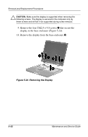
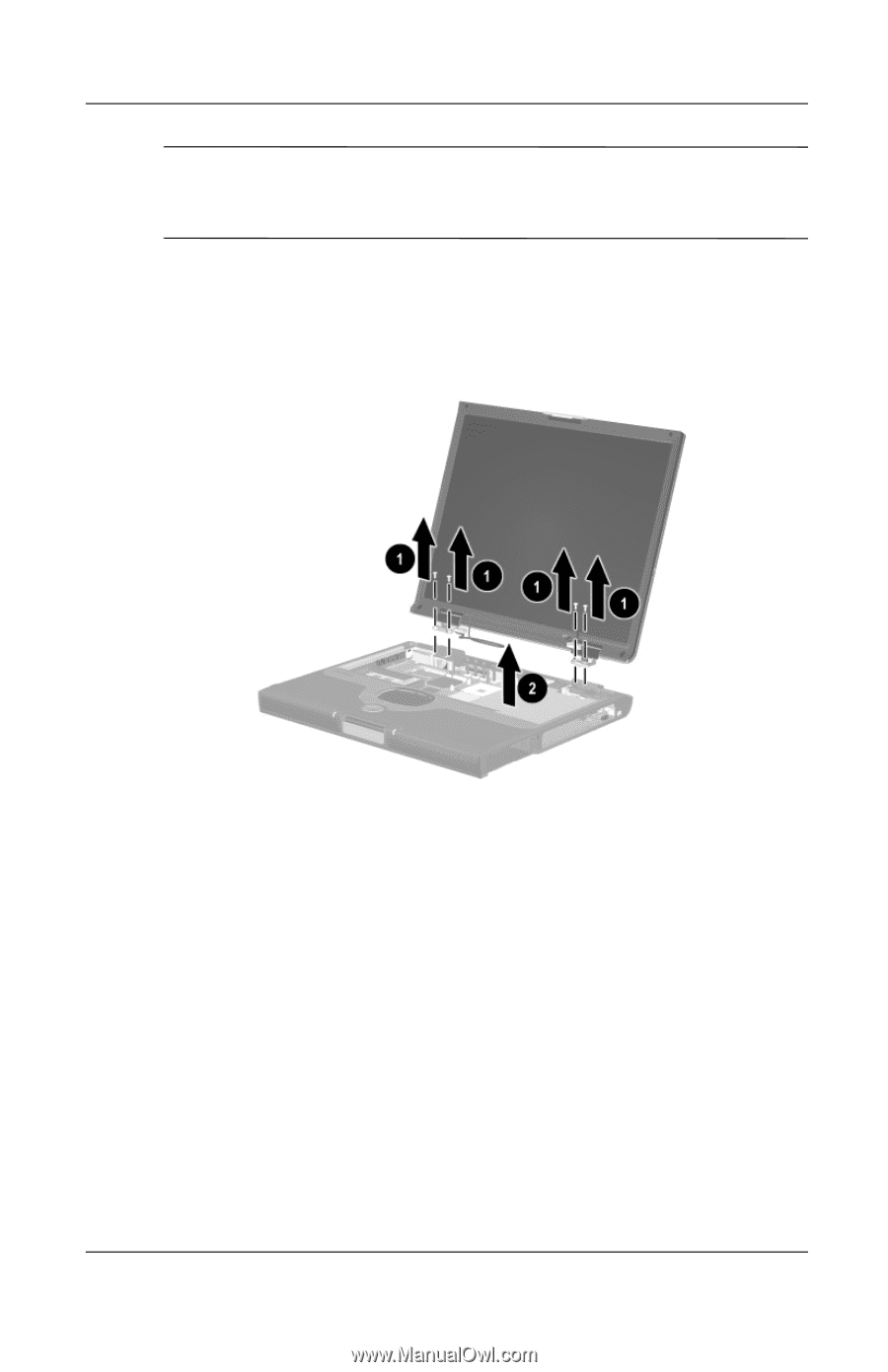
Removal and Replacement Procedures Ä CAUTION: Make sure the display is supported when removing the following screws. The display is secured to the computer only by these screws and will fall if not supported during screw removal. 9. Remove the four TM2.5 × 9.0 screws 1 that secure the display to the base enclosure (Figure 5-24). 10. Remove the display from the base enclosure 2. Figure 5-24. Removing the Display 5-32 Maintenance and Service Guide
-
 1
1 -
2
-
3
-
4
-
5
-
6
-
7
-
8
-
9
-
10
-
11
-
12
-
13
-
14
-
15
-
16
-
17
-
18
-
19
-
20
-
21
-
22
-
23
-
24
-
25
-
26
-
27
-
28
-
29
-
30
-
31
-
32
-
33
-
34
-
35
-
36
-
37
-
38
-
39
-
40
-
41
-
42
-
43
-
44
-
45
-
46
-
47
-
48
-
49
-
50
-
51
-
52
-
53
-
54
-
55
-
56
-
57
-
58
-
59
-
60
-
61
-
62
-
63
-
64
-
65
-
66
-
67
-
68
-
69
-
70
-
71
-
72
-
73
-
74
-
75
-
76
-
77
-
78
-
79
-
80
-
81
-
82
-
83
-
84
-
85
-
86
-
87
-
88
-
89
-
90
-
91
-
92
-
93
-
94
-
95
-
96
-
97
-
98
-
99
-
100
-
101
-
102
-
103
-
104
-
105
-
106
-
107
-
108
-
109
-
110
-
111
-
112
-
113
-
114
-
115
-
116
-
117
-
118
-
119
-
120
-
121
-
122
-
123
-
124
-
125
-
126
-
127
-
128
-
129
-
130
-
131
-
132
-
 133
133 -
 134
134 -
 135
135 -
 136
136 -
 137
137 -
 138
138 -
 139
139 -
 140
140 -
 141
141 -
 142
142 -
 143
143 -
144
-
145
-
146
-
147
-
148
-
149
-
150
-
151
-
152
-
153
-
154
-
155
-
156
-
157
-
158
-
159
-
160
-
161
-
162
-
163
-
164
-
165
-
166
-
167
-
168
-
169
-
170
-
171
-
172
-
173
-
174
-
175
-
176
-
177
-
178
-
179
-
180
-
181
-
182
-
183
-
184
-
185
-
186
-
187
-
188
-
189
-
190
-
191
-
192
-
193
-
194
-
195
-
196
-
197
-
198
-
199
-
200
-
201
-
202
-
203
-
204
-
205
-
206
-
207
-
208
-
209
-
210
-
211
-
212
-
213
-
214
-
215
-
216
-
217
-
218
-
219
 |
 |
5–32
Maintenance and Service Guide
Removal and Replacement Procedures
Ä
CAUTION:
Make sure the display is supported when removing the
following screws. The display is secured to the computer only by
these screws and will fall if not supported during screw removal.
9. Remove the four TM2.5 × 9.0 screws
1
that secure the
display to the base enclosure (Figure 5-24).
10. Remove the display from the base enclosure
2
.
Figure 5-24. Removing the Display