HP J9146A Installation Guide
HP J9146A - ProCurve Switch 2910al-24G-PoE Manual
 |
UPC - 884420766971
View all HP J9146A manuals
Add to My Manuals
Save this manual to your list of manuals |
HP J9146A manual content summary:
- HP J9146A | Installation Guide - Page 1
ProCurve 2910al Switches Installation and Getting Started Guide Power over Ethernet - HP J9146A | Installation Guide - Page 2
- HP J9146A | Installation Guide - Page 3
ProCurve 2910al Switches Installation and Getting Started Guide - HP J9146A | Installation Guide - Page 4
, L.P. Publication Number 5992-3084 March 2010 Applicable Products HP ProCurve 2910al-24G Switch HP ProCurve 2910al-48G Switch HP ProCurve 2910al-24G-PoE+ Switch HP ProCurve 2910al-48G-PoE+ Switch HP ProCurve 2-Port 10-GbE CX4 al Module HP ProCurve 2-Port 10-GbE SFP+ al Module HP ProCurve 10-GbE - HP J9146A | Installation Guide - Page 5
1-8 Reset Button 1-10 Clear Button 1-10 Console Port 1-11 Expansion Module LEDs 1-11 Back of the Switch 1-12 al Module Slots 1-12 RPS and EPS Input Ports 1-13 Power Connector 1-13 HP ProCurve Switch al Modules 1-14 Features 1-15 Switch Features 1-16 2 Installing the Switch Included Parts - HP J9146A | Installation Guide - Page 6
/EPS (J8696A 2-19 620 RPS/EPS Connectivity 2-21 Operating characteristics of the HP ProCurve 630 RPS/EPS (J9443A) 2-22 HP ProCurve 630 RPS/EPS Connectivity 2-24 9. (Optional) Connect a Console to the Switch 2-24 Terminal Configuration 2-25 Direct Console Access 2-25 Console Cable Pinouts 2-26 - HP J9146A | Installation Guide - Page 7
End-to-End Network Communications 4-10 Restoring the Factory Default Configuration 4-11 Downloading New Switch Software 4-12 HP Customer Support Services 4-12 Before Calling Support 4-12 A Switch Specifications Physical A-1 Electrical A-1 Environmental A-1 Acoustic A-2 Safety A-2 B Module - HP J9146A | Installation Guide - Page 8
Installing the Patch Cord C-5 Twisted-Pair Cable/Connector Pin-Outs C-6 Straight-Through Twisted-Pair Cable for 10 Mbps or 100 Mbps Network Connections C-7 Cable Diagram C-7 Pin Assignments C-7 Crossover Twisted-Pair Cable for 10 Mbps or 100 Mbps Network Connection C-8 Cable Diagram C-8 Pin - HP J9146A | Installation Guide - Page 9
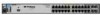
2 flash = 100 Mbps on = 1 Gbps 3 flash = 10 Gbps Fan PoE Test Usr Reset Clear Auxiliary Port HP ProCurve 2910al-24G-PoE+ Switch (J9146A) PoE+ Integrated 10/100/1000Base-T Ports (1 - 24T) — Ports are Auto-MDIX Dual-Personality Ports: 10/100/1000-T (T) or SFP (S) Link 1 Mode 3 5 7 9 11 - HP J9146A | Installation Guide - Page 10
Switch Introducing the Switch The 2910al-24G Switch and 2910al-48G Switch have respectively, 24 or 48, auto-sensing 10/100/1000Base-T RJ-45 ports, four dual-personality ports- either auto-sensing 10/100/1000Base-T RJ-45 or mini-GBIC, and two slots are provided in the back of the device to support - HP J9146A | Installation Guide - Page 11
-45 port will not be supplied with PoE power and will be disabled. For more information regarding the PoE capabilities of the 2910al Switches, see the ProCurve PoE (Power over Ethernet) Devices Planning and Implementation Guide, which is on the ProCurve Web site at www.hp.com/go/procurve/manuals. HP - HP J9146A | Installation Guide - Page 12
22T 24T Link 22S Mode 24S 10/100/1000Base-T RJ-45 Dual-personality ports (1000Base-T or mini-GBIC) Figure 1-1. HP ProCurve 2910al-24G Switch Power, Fault, and Locator LEDs PoE, Temp, Fan, and Test Status LEDs Module, and RPS, Status LEDs Switch port LEDs ProCurve Switch Mdl * RPS Status of - HP J9146A | Installation Guide - Page 13
18 20 22T 24T Link 22S Mode 24S ! Use only one (T or S) for each Port Console port Port LED Mode select button and indicator LEDs Reset and Clear buttons 10/100/1000Base-T RJ-45 Figure 1-3. HP ProCurve 2910al-24G-PoE+ Switch Dual-personality ports (1000Base-T or mini-GBIC) Power, Fault - HP J9146A | Installation Guide - Page 14
-through or crossover twisted-pair cables to connect any network devices to the switch. ■ On the 2910al devices there are four dual-personality ports. Use either the 10/100/1000Base-T RJ-45 connector, or install a supported ProCurve miniGBIC (SFP) for fiber-optic connections. The RJ-45 connectors - HP J9146A | Installation Guide - Page 15
PoE Usr On Flashing Off Meaning The Locator LED is used to locate a specific chassis in a area full of chassis. The LED can be set to be on solid or flash for a specified number of minutes (1-1440). The default is 30 minutes. Use the command "chassislocate". The normal operational state; the switch - HP J9146A | Installation Guide - Page 16
If any port is denied PoE power or detecting an external PD fault Temp (green/Orange) Off Flashing1 Switch temperature is normal. An over temperature condition has been detected. Auxiliary (green/ orange) For more information see the Management and Configuration Guide for your switch. Flashing - HP J9146A | Installation Guide - Page 17
20 22 24 Link 26 Mode 28 30 LED Mode select button and indicator LEDs Figure 1-6. HP ProCurve 2910al-48G-PoE+ Switch ■ The PoE+ switches have an additional mode, PoE. In PoE mode, the Link LED indicates the PoE configuration for the port: • On if PoE is enabled on the port • Off if PoE is - HP J9146A | Installation Guide - Page 18
, and the factory default configuration is restored to the switch. For the specific method to restore the factory default configuration, see "Restoring the Factory Default Configuration" on page 11, "Troubleshooting" of this manual. Clear Button This button is used for: ■ Deleting Passwords - When - HP J9146A | Installation Guide - Page 19
. Expansion Module LEDs "Expansion Module" LEDs refer to the LEDs specific to the expansion module. These LEDs are located on the physical expansion module bulkhead. These LEDs are only viewable in the rear of the Switch 2910al-48G product on the Expansion Slot Module itself. Table 1-3. Expansion - HP J9146A | Installation Guide - Page 20
A 200-240 V~ 5 A al module slot RPS Input Port Figure 1-8. HP ProCurve 2910al-24G-PoE+ Switch al Module Slots AC power connector It is required for the switch to be powered down before inserting or extracting the Expansion Module. These switches support three al modules. The al modules provide - HP J9146A | Installation Guide - Page 21
fails. The EPS functionality of the HP ProCurve 620 RPS/EPS is not supported on the 2910al switches, however, the HP ProCurve 630 RPS/EPS provides redundant or additional PoE+ power to the 2910al PoE+ switches. Power Connector The 2910al Switches do not have a power switch; they are powered on when - HP J9146A | Installation Guide - Page 22
HP ProCurve accessories are supported by the HP ProCurve Switch 2-Port 10-GbE CX4 al Module: • ProCurve 10-GbE CX4 Media Converter (J8439A). 2 Supported transceivers: As of this printing the following HP ProCurve transceivers are supported by the HP ProCurve Switch al 10-GbE 2-port SFP+ Module: • HP - HP J9146A | Installation Guide - Page 23
the Switch Features HP ProCurve 10-GbE CX4 al Module Link and Mode LEDs (one pair per port) Copper CX4 port connections Retaining screw Figure 2. Front of the al 10-GbE CX4 Module The al Modules have the following features: ■ Connectivity ports. ■ LEDs that provide information for each port on - HP J9146A | Installation Guide - Page 24
the Switch Introducing the Switch Switch Features Switch Features The features of the 2910al Switch include: ■ 24 or 48 auto-sensing 10/100/1000Base-T RJ-45 ports with Auto-MDIX. ■ Four dual-personality ports-either the auto sensing 10/100/1000Base-T RJ-45 or the mini-GBIC can be used for each port - HP J9146A | Installation Guide - Page 25
the Management and Configuration Guide, which is on the ProCurve Web site www.hp.com/go/procurve/manuals. ■ Download of new switch software for product enhancements or bug fixes. ■ Support for IEEE 802.3af and 802.3at standard and Pre-standard PoE and PoE+ devices. ■ Support for SFP+ transceivers at - HP J9146A | Installation Guide - Page 26
- HP J9146A | Installation Guide - Page 27
Parts The 2910al Switches have the following components shipped with them: ■ HP ProCurve Switch Quick Setup guide ■ HP ProCurve Switches General Safety and Regulatory Information booklet ■ 2910al Switch Specific Safety and Regulatory Information sheet ■ Read Me First ■ Customer Support/Warranty - HP J9146A | Installation Guide - Page 28
the Switch Included Parts ■ Accessory kit (5069-5705) two mounting brackets eight 8-mm M4 screws to attach the mounting brackets to the switch four 5/8-inch number 12-24 screws to attach the switch to a rack four rubber feet ■ Power cord, one of the following: Non-PoE Switches PoE+ Switches - HP J9146A | Installation Guide - Page 29
and progressively lighter devices installed above. ■ Do not wall mount any of the 2910al Switches. ■ If the switch is to be shipped in a rack, be sure to use only an HP 10K rack. Mount the switch using rail kit part number 356578-B21 and shelf kit AB469A. Both kits must be used. Otherwise you will - HP J9146A | Installation Guide - Page 30
Figure 2-1. Air flow direction of the 2910al switch Installation Procedures Summary 1. Prepare the installation site (page 2-5). Ensure the physical environment is properly prepared, including having the correct network cabling ready to connect to the switch and having an appropriate location for - HP J9146A | Installation Guide - Page 31
to use an HP ProCurve external power supply, either the 620 RPS/ EPS or the 630 RPS/EPS with your 2910-PoE+ switch. To do so you must connect the external power supply using the RPS or EPS cables supplied with these devices. 9. (Optional) Connect a console to the switch (page 2-24). You may wish - HP J9146A | Installation Guide - Page 32
21 23 Link 25 Mode 27 29 31 Power J9147A Fault Locator Status Tmp LED Mode Fan Act FDx Spd * Test Usr Console Reset Clear Link 2 Mode 4 6 8 10 12 Link 14 Mode 16 18 20 22 24 Link 26 Mode 28 30 32 Test LED Figure 2-3. Checking the LEDs on the 2910al non-PoE switches - HP J9146A | Installation Guide - Page 33
Spd * Fan PoE Test Usr Console Reset Clear Link 2 Mode 4 6 8 10 12 Link 14 Mode 16 18 20 22 24 Link 26 Mode 28 30 32 Test LED Figure 2-4. Checking the LEDs on the 2910al-PoE+ switches LED Behavior: During the self test: • Initially, all the status, LED Mode and port LEDs are - HP J9146A | Installation Guide - Page 34
powered on without interrupting the operation of the rest of the switch ports. If you install or remove an expansion al module with the switch powered on, a reboot may be required for the module to be recognized. HP ProCurve recommends inserting or removing modules during scheduled downtime with the - HP J9146A | Installation Guide - Page 35
Procedures Installing the Interconnect Kit The Interconnect Kit consists of two, 1-port 10 Gigabit switch expansion modules (J9165A) and one 0.5 meter cable used specifically for this interconnect kit. These modules have 1 fixed CX4 port each. The interconnect kit is used for 10-GbE (high speed - HP J9146A | Installation Guide - Page 36
Power Fault Locator Console ProCurve Switch 2910bl-24G-PoE Mdl EPS RPS Status of the Back J9146A PoE+ * Spd mode: Status PoE LED Tmp Mode Act FDx Spd * off = 10 Mbps 2 flash = 100 Mbps on = 1 Gbps 3 flash = 10 Gbps Fan PoE Test Usr Reset Clear Auxiliary Port Figure 2-8. Location of - HP J9146A | Installation Guide - Page 37
surface On a wall Non-PoE Switches Yes Yes No PoE Switches Yes Yes No Rack or Cabinet Mounting The 2910al Switches are designed to be mounted screws that came with the cabinet in place of the 12-24 screws that are supplied with the switch. Complete step 1, and plan which four holes you will - HP J9146A | Installation Guide - Page 38
2-9. Attaching mounting brackets The mounting brackets have multiple mounting holes and can be rotated allowing for a wide variety of mounting options. These include mounting the switch so its front face is flush with the face of the rack, or mounting it in a more balanced position. Installing the - HP J9146A | Installation Guide - Page 39
number 12-24 screws holding the brackets to the rack. Installing the Switch Caution Figure 2-10. Mounting in a rack Horizontal Surface Mounting Place the switch on a table or other horizontal surface. The switch networking cables and switch power cord to the table leg or other part of the surface - HP J9146A | Installation Guide - Page 40
Procedures 5. (Optional) Install a Transceiver Note Hot swapping transceivers is supported. You can install or remove a transceiver with the switch powered on, a reset will not occur. However, rapid hotswaps are not recommended. Wait 5 seconds between hotswaps. a. Slide the transceiver - HP J9146A | Installation Guide - Page 41
Installing the Switch Installing the Switch Installation Procedures Installing or Removing the Optical Media Converter You can connect an Optical Media Converter (OMC) to the fixed ports only. Use only HP ProCurve OMCs. Installing the OMC: 1. Connect the OMC to the fixed port. 2. Push it until it - HP J9146A | Installation Guide - Page 42
. Should you require additional ProCurve mini-GBICs, contact your ProCurve Networking Sales and Service Office or authorized dealer. Notes ■ Hot swapping mini-GBICs and transceivers is supported. You can install or remove a transceiver with the switch powered on, a reset will not occur. However - HP J9146A | Installation Guide - Page 43
direct eye exposure to the beam coming from the transmit port. Removing the mini-GBICs You should disconnect the network cable from the mini-GBIC before removing it from the switch. Depending on when you purchased your ProCurve mini-GBIC, it may have either of three different release mechanisms - HP J9146A | Installation Guide - Page 44
will be supplied from the 620 RPS/EPS. ■ The J9443A, HP ProCurve 630 Redundant and/or External Power Supply (HP ProCurve 630 RPS/EPS) for RPS and EPS power. The 2910al switches support both the RPS and the EPS of the HP ProCurve 630 RPS/EPS. These external power supplies are unmanaged power supplies - HP J9146A | Installation Guide - Page 45
ProCurve Web site at www.hp.com/go/procurve/manuals. Operating Characteristics of the 620 RPS/EPS (J8696A) The 620 RPS/EPS has two RPS ports, each of which can provide redundant +12V power to a connected switch. If a switch has two EPS Ports which can not be used with the 2910al Switches. 620 RPS/EPS - HP J9146A | Installation Guide - Page 46
after the unit is powered on or reset, at the beginning of unit self port. 1 The flashing behavior is an on/off cycle once every 1.6 seconds, approximately. 2 The flashing behavior is an on/off cycle once every 0.8 seconds, approximately. 3 Specific fault conditions can be viewed by checking switch - HP J9146A | Installation Guide - Page 47
connection topologies using the 620 RPS/EPS. The 620 RPS/EPS can provide backup power support for up to two ProCurve switches. In the illustration below, two ProCurve Switch 2910s are connected to the RPS ports on a 620 RPS/EPS. Serial No. SG12345678 System MAC Address 00 - 01 - E7 - 12 - 34 - HP J9146A | Installation Guide - Page 48
the supplied RPS cable. The RPS cable is 2 meters (6.56 feet) in length. The HP ProCurve 630 RPS/EPS also has one EPS Port which can supply backup or extra PoE+ power at 54V to the 2910al Switch. HP ProCurve 630 RPS/EPS LEDs The HP ProCurve 630 RPS/EPS LEDs are located on the front and back of the - HP J9146A | Installation Guide - Page 49
normally. A cooling fan has failed. The unit Fault LED will be flashing simultaneously. Port Status (also on back panel of the HP ProCurve 630 RPS/EPS) Device Connected On (green - over-laid with the port Off number) There is a valid connection to a device. There is no valid device connected - HP J9146A | Installation Guide - Page 50
, see chapter 3, "Getting Started With Switch Configuration", and the Management and Configuration Guide, which is on the HP ProCurve Web site at www.hp.com/go/procurve/manuals. The Switch can simultaneously support one out-of-band console session through the Console Port and one in-band Telnet - HP J9146A | Installation Guide - Page 51
to 25-pin straight-through adapter at one end of the console cable.) Console port Console cable supplied with the switch 2. Turn on the terminal or PC's power and, if using a PC, a key, and you will then see the switch console command (CLI) prompt, for example: ProCurve Switch 2910al-24G# 2-25 - HP J9146A | Installation Guide - Page 52
this time, see chapter 3, "Getting Started With Switch Configuration" for some basic configuration steps. For more detailed information, refer to the Management and Configuration Guide, which is on the ProCurve Website at www.hp.com/ go/procurve/manuals. Console Cable Pinouts The console cable has - HP J9146A | Installation Guide - Page 53
the switch ports, when a network cable from an active network device is connected to the port, the port LED for that port should go on. If the port LED does not go on when the network cable is connected to the port, see "Diagnosing with the LEDs" on page 4-4 in chapter 5, "Troubleshooting". 2-27 - HP J9146A | Installation Guide - Page 54
snaps into place. 2 If the Link LED does not go on when the network cable is connected to the port, see "Diagnosing with the LEDs" on page 4-4, in chapter 5, "Troubleshooting". To disconnect: Pull the cable connector straight out. Connecting a copper cable To connect: 1. Push the copper cable - HP J9146A | Installation Guide - Page 55
For more topology information, see the ProCurve network products Website, www.hp.com/go/procurve. Servers Gigabit fiber cable ProCurve Switch 5406zl ProCurve Switch 2910al Gigabit copper cable PCs and peripherals Figure 2-21. Example, gigabit edge deployment The Switch 2910al can be used at the - HP J9146A | Installation Guide - Page 56
Installing the Switch Installing the Switch Sample Network Topologies Servers 10 Gigabit fiber cable Gigabit copper cable 10 Gigabit copper cables ProCurve Switch 2910al ProCurve Switch 5406zl PCs and peripherals Figure 2-22. Example, high performance edge deployment 2-30 - HP J9146A | Installation Guide - Page 57
5412zl 10 Gigabit copper cables Gigabit copper cable High speed internet uplinks 10 Gigabit copper cables Installing the Switch Sample Network Topologies ProCurve Switch 2910al 10 Gigabit fiber cable Servers with Gigabit Ethernet NIC Servers with Gigabit Ethernet NIC Figure 2-23. Example - HP J9146A | Installation Guide - Page 58
Installing the Switch Installing the Switch Sample Network Topologies Servers ProCurve Switch 5406zl 10 Gigabit fiber cable 10 Gigabit copper cables Gigabit copper cable ProCurve Switch 2910al PCs, peripherals and access points Figure 2-24. Example, PoE edge deployment 2-32 - HP J9146A | Installation Guide - Page 59
please see the Management and Configuration Guide, which is on the ProCurve Website at www.hp.com/go/procurve/manuals. Recommended Minimal Configuration In the factory default configuration, the switch has no IP (Internet Protocol) address and subnet mask, and no passwords. In this state, it can be - HP J9146A | Installation Guide - Page 60
By default, the switch is configured to acquire an IP address configuration from a DHCP or Bootp server. To use DHCP/Bootp instead of the manual method described in this chapter, see "DHCP/Bootp Operation" in the Management and Configuration Guide, which is on the ProCurve Website at www.hp.com - HP J9146A | Installation Guide - Page 61
and subnet mask assigned for the switch must be compatible with the IP addressing used in your network. For more information on IP addressing, see the Management and Configuration Guide, which is on the ProCurve Website at www.hp.com/go/procurve/manuals. Subnet Mask xxx.xxx.xxx.xxx Recommended - HP J9146A | Installation Guide - Page 62
interfaces and all the features that can be configured on the al switches, see the Management and Configuration Guide, which is on the ProCurve Website at www.hp.com/go/procurve/manuals. To Recover from a Lost Manager Password If you cannot start a console session at the manager level because of - HP J9146A | Installation Guide - Page 63
that is on the same subnet as the switch and connect to the switch's IP address. 3. You will see the copyright page and the message "Press any key to continue". Press a key, and you will then see the switch console command (CLI) prompt, for example: ProCurve Switch 2910al-48G# Enter help or ? to see - HP J9146A | Installation Guide - Page 64
ve Switch 2910al-48G - Satus: Information J9147A ProCurve Switch1 2910al-48G PoE Status Getting Started With Switch Configuration For more information on using the web browser interface, see the Management and Configuration Guide, which is on the ProCurve Website at www.hp.com/go/procurve/manuals - HP J9146A | Installation Guide - Page 65
Tools (page 4-8) ■ Hardware Diagnostic Tests (page 4-9) ■ Restoring the Factory Default Configuration (page 4-11) ■ Downloading New Switch Software (page 4-12) ■ HP Customer Support Services (page 4-12) Basic Troubleshooting Tips Most problems are caused by the following situations. Check for these - HP J9146A | Installation Guide - Page 66
2910al Switch devices also support Trunking, which allows multiple network cables to be used for a single network connection without causing a data path loop. For more information on Spanning Tree and Trunking, see the Management and Configuration Guide, which is on the ProCurve Website at www.hp - HP J9146A | Installation Guide - Page 67
switch features that may be affecting the port. For more information, see the Management and Configuration Guide, which is on the ProCurve Website at www.hp.com/go/procurve/manuals. For more information on possible network problems and their solutions, refer to the technical note "Troubleshooting - HP J9146A | Installation Guide - Page 68
Troubleshooting Troubleshooting Diagnosing with the LEDs Diagnosing with the LEDs Table 4-1 shows LED patterns on the switch and the switch modules that indicate problem conditions. 1. Check in the table for the LED pattern you see on your switch * On, but the port is ➐ not communicating On - HP J9146A | Installation Guide - Page 69
failure Call your ProCurve authorized LAN dealer, or use the electronic support services from HP has occurred. All to get assistance. See the Customer Support/Warranty booklet for more information. the LEDs will stay on indefinitely. ➌ The switch has 1. Try resetting the switch by pressing the - HP J9146A | Installation Guide - Page 70
Troubleshooting Troubleshooting Diagnosing with the LEDs Tip Problem Solution ➏ The network Try the following procedures: connection is not • For the indicated port, verify both ends of the cabling, at the switch and the connected working device, are connected properly. properly. • Verify - HP J9146A | Installation Guide - Page 71
VLANs and IGMP. Use the switch console to see how the port is configured for these features. For software troubleshooting tips, see the chapter "Troubleshooting" in the Management and Configuration Guide, which is on the ProCurve Website at www.hp.com/go/procurve/ manuals. Make sure also, the - HP J9146A | Installation Guide - Page 72
interface is also accessible through a Telnet connection. For more information on using these software tools to diagnose and manage your switch, see the "Troubleshooting" chapter in the Management and Configuration Guide, which is on the ProCurve Website at www.hp.com/go/ procurve/manuals. 4-8 - HP J9146A | Installation Guide - Page 73
Troubleshooting Troubleshooting Hardware Diagnostic Tests Hardware Diagnostic Tests Testing the Switch by Resetting It If you believe the switch is not operating correctly, you can reset the switch to test its circuitry and operating code. To reset a switch, either: ■ unplug and plug in the power - HP J9146A | Installation Guide - Page 74
interface from a terminal connected to the switch or through a Telnet connection, or from the switch's web browser interface. For more information, see the Management and Configuration Guide, which is on the ProCurve Website at www.hp.com/ go/procurve/manuals. These tests can also be performed from - HP J9146A | Installation Guide - Page 75
the Management and Configuration Guide, which is on the ProCurve Website at www.hp.com/go/procurve/manuals. You can restore the factory default configuration either on the switch itself, or through the switch console. To execute the factory default reset on the switch, perform these steps: 1. Using - HP J9146A | Installation Guide - Page 76
Guide, which is on the ProCurve Website at www.hp.com/go/ procurve/manuals. The new switch software would be available on the ProCurve Website at www.hp.com/go/procurve/software. HP Customer Support Services If you are still having trouble with your switch, Hewlett-Packard offers support 24 - HP J9146A | Installation Guide - Page 77
Switch Specifications A Switch Specifications Physical 2910al-24G (J9145A) 2910al-48G (J9147A) 2910al-24G-PoE+ (J9146A) 2910al-48G-PoE+ (J9148A) Width: 44.19 cm (17.4 in) 44.19 cm (17.4 in) 44.19 cm (17.4 in) 44.19 cm (17.4 in) Depth: 36.57 - HP J9146A | Installation Guide - Page 78
Switch Specifications Switch Specifications Acoustic ProCurve Switch 2910al-24G (J9145A) Geraeuschemission LpA=41.1 dB am fiktiven Arbeitsplatz nach DIN 45635 T.19 Noise Emission LpA=41.1 dB at virtual workspace according to DIN 45635 T.19 ProCurve Switch 2910al-48G (J9147A) Geraeuschemission LpA= - HP J9146A | Installation Guide - Page 79
Switch Specifications Switch Specifications Table A-1. Technology standards and safety compliance Technology 10/100/1000-T 100-FX 100-BX 1000-SX 1000-LX 1000-LH 1000-BX 10-Gig CX4 - HP J9146A | Installation Guide - Page 80
- HP J9146A | Installation Guide - Page 81
F) 15% to 90% at 65C (149F) 3.0 Km (10,000 ft) 4.6 Km (15,000 ft) Optical Power Specifications See the tranceiver specifications which is on the ProCurve Website at www.hp.com/go/procurve/faqs, go to "ProCurve Mini-GBICs and Transceivers" and click on "ProCurve 10-GbE transceivers" and go to - HP J9146A | Installation Guide - Page 82
- HP J9146A | Installation Guide - Page 83
should be used with the Switch 2910al, including minimum pin-out information and specifications for twisted-pair cables. Incorrectly wired cabling is the most common cause of problems for LAN communications. ProCurve recommends that you work with a qualified LAN cable installer for assistance with - HP J9146A | Installation Guide - Page 84
most robust connections you should use cabling that complies with the Category 5e specifications, as described in Addendum 5 to the TIA-568-A standard (ANSI/ your cabling, be sure to include the patch cables that connect the switch and other end devices to the patch panels on your site. The patch - HP J9146A | Installation Guide - Page 85
Cabling and Technology Information Technology distance specifications Table C-2. Technology Supported cable type Multimode fiber modal bandwidth Supported distances 100-FX multimode fiber any up to 2,000 meters 100-BX single mode fiber N/A 0.5 - 10,000 meters 1000-T twisted-pair - HP J9146A | Installation Guide - Page 86
cable to provide the transmission conditioning. If you experience a high number of transmission errors on those ports, usually CRC or FCS errors, you may need to install one of these patch cords between the fiber-optic port in your switch and your multimode fiber-optic network cabling, at both ends - HP J9146A | Installation Guide - Page 87
the patch cord to the ProCurve transceiver with the section of single mode fiber plugged in to the Tx (transmit) port. Then, connect the other adapter to allow the cables to be connected together. Gigabit-LX port Rx Tx To network multimode cabling Mode Conditioning Patch Cord The multimode - HP J9146A | Installation Guide - Page 88
Pin-Outs Auto-MDIX Feature: The 10/100/1000-T ports support the IEEE 802.3ab standard, which includes the "Auto MDI/MDI-X" feature. In the default configuration, "Auto", the ports on the Switch 2910al all automatically detect the type of port on the connected device and operate as either an MDI - HP J9146A | Installation Guide - Page 89
Straight-Through Twisted-Pair Cable for 10 Mbps or 100 Mbps Network Connections Because of the HP Auto-MDIX operation of the 10/100 ports on the switch, for all network connections, to PCs, servers or other end nodes, or to hubs or other switches, you can use straight-through cables. If any of these - HP J9146A | Installation Guide - Page 90
Mbps or 100 Mbps Network Connection The HP Auto-MDIX operation of the 10/100 ports on the switch also allows you to use crossover cables for all network connections, to PCs, servers or other end nodes, or to hubs or other switches. If any of these ports are given a fixed configuration, for example - HP J9146A | Installation Guide - Page 91
Cabling and Technology Information Straight-Through Twisted-Pair Cable for 1000 Mbps Network Connections 1000Base-T connections require that all four pairs or wires be connected. Cable Diagram Cabling and Technology Information Note . Pins 1 and 2 on connector "A" must be wired as a twisted pair - HP J9146A | Installation Guide - Page 92
- HP J9146A | Installation Guide - Page 93
manual denotes a hazard that can cause injury or death. A Caution in the manual Servicing There are no user-serviceable parts inside these products. Any servicing, adjustment, maintenance, or repair must be performed only by service-trained personnel. These products do not have a power switch - HP J9146A | Installation Guide - Page 94
Safety and EMC Regulatory Statements Safety and EMC Regulatory Statements Informations concernant la sécurité Informations concernant la sécurité ! WARNING Caution Symbole de référence à la documentation. Si le produit est marqué de ce symbole, reportez-vous à la documentation du produit afin d' - HP J9146A | Installation Guide - Page 95
der Schutz beeinträchtigt worden ist, das Netzkabel aus der Wandsteckdose herausziehen, bis die Erdung wiederhergestellt ist. Für LAN-Kabelerdung: ■ Wenn Ihr LAN ein Gebiet umfaßt, das von mehr als einem Stromverteilungssystem beliefert wird, müssen Sie sich vergewissern, daß die Sicherheitserdungen - HP J9146A | Installation Guide - Page 96
protezione, disinserite il cavo d'alimentazione fino a quando il collegaento a terra non sia stato ripristinato. Per la messa a terra dei cavi LAN: ■ se la vostra LAN copre un'area servita da più di un sistema di distribuzione elettrica, accertatevi che i collegamenti a terra di sicurezza siano ben - HP J9146A | Installation Guide - Page 97
la red de energía eléctrica). Manejar con precaución los componentes de metal de la LAN que estén al descubierto. Este aparato no contiene pieza alguna susceptible de reparación por parte del usuario. Todas las reparaciones, ajustes o servicio de mantenimiento debe realizarlos solamente el técnico - HP J9146A | Installation Guide - Page 98
Safety and EMC Regulatory Statements Safety and EMC Regulatory Statements Safety Information (Japan) Safety Information (Japan) Japan Power Cord Warning D-6 - HP J9146A | Installation Guide - Page 99
Safety and EMC Regulatory Statements Safety and EMC Regulatory Statements Safety Information (China) Safety Information (China) D-7 - HP J9146A | Installation Guide - Page 100
to comply with the limits for a Class A digital device, pursuant to Part 15 of the FCC Rules. These limits are designed to provide reasonable energy and, if not installed and used in accordance with the instruction manual, may cause interference to radio communications. Operation of this equipment - HP J9146A | Installation Guide - Page 101
Safety and EMC Regulatory Statements Korea Taiwan Safety and EMC Regulatory Statements EMC Regulatory Statements D-9 - HP J9146A | Installation Guide - Page 102
HP ProCurve 2910al Switch Series Product Number(s): J9145A, J9147A Regulatory Model No1: RSVLC-0703 Product Options: All conforms to the following Product Specifications 1993 +A2 Class 1 Supplementary Information: The device complies with part 15 of the FCC Rules. Operation is subject to the - HP J9146A | Installation Guide - Page 103
HP ProCurve 2910al Switch Series Product Number(s): J9146A, J9148A Regulatory Model No1: RSVLC-0705 Product Options: All conforms to the following Product Specifications 1993 +A2 Class 1 Supplementary Information: The device complies with part 15 of the FCC Rules. Operation is subject to the - HP J9146A | Installation Guide - Page 104
- HP J9146A | Installation Guide - Page 105
more information about where you can drop off your waste equipment for recycling, please contact your local city office, your household waste disposal service or the shop where you purchased the product. Likvidace zařízení soukromými domácími uživateli v Evropské unii Tento symbol na produktu nebo - HP J9146A | Installation Guide - Page 106
d'informations sur les centres de collecte et de recyclage des appareils mis au rebut, veuillez contacter les autorités locales de votre région, les services de collecte des ordures ménagères ou le magasin dans lequel vous avez acheté ce produit. Entsorgung von Altgeräten aus privaten Haushalten in - HP J9146A | Installation Guide - Page 107
Recycle Statements Recycle Statements Waste Electrical and Electronic Equipment (WEEE) Statements Smaltimento delle apparecchiature da parte di privati nel territorio dell'Unione Europea Questo simbolo presente sul prodotto o sulla sua confezione indica che il prodotto non può essere smaltito - HP J9146A | Installation Guide - Page 108
es sobre locais que reciclam esse tipo de material, entre em contato com o escritório da HP em sua cidade, com o serviço de coleta de lixo ou com a loja em que . Eliminación de residuos de equipos eléctricos y electrónicos por parte de usuarios particulares en la Unión Europea Este símbolo en el - HP J9146A | Installation Guide - Page 109
2-25 configuration checking when troubleshooting ... 4-3 DHCP/Bootp ... 3-2 full duplex only for mini-GBICs ... 2-16 IP address ... 3-3 IP address, manually ... 3-2 manager password ... 3-2 restoring factory defaults ... 1-10, 4-11 subnet mask ... 3-3 switch setup screen ... 3-2 connecting external - HP J9146A | Installation Guide - Page 110
switch ... 1-6 operation description ... 1-6 E electrical specifications, switch ... A-1 EMC regulatory statements ... D-8 environmental specifications, switch ... A-1, B-1 EPS input port ... 1-13 expansion module LEDs ... 1-11 external power supply connecting ... 2-18 2 - Index F factory default - HP J9146A | Installation Guide - Page 111
surface ... 2-13 N network cables fiber-optic, specifications ... C-3 HP Auto-MDIX feature ... C-6 required types ... 2-5 twisted-pair connector pin-outs ... C-6 twisted-pair, wiring rules ... C-6 network devices connecting to the switch ... 2-27 network ports connecting to ... 2-27 location on - HP J9146A | Installation Guide - Page 112
... 4-11 resetting the switch factory default reset ... 4-11 location of Reset button ... 1-10 troubleshooting procedure ... 4-9 RPS/EPS connectivity ... 2-21, 2-24 RPS/EPS LEDs ... 2-19, 2-22 S safety and regulatory statements ... D-1 safety specifications ... A-2 selecting the Port LED View - HP J9146A | Installation Guide - Page 113
switch connecting to a power source ... 2-18 description ... 1-1 downloading new software ... 4-12 electrical specifications ... A-1 environmental specifications ... A-1, B-1 features ... 1-16 front panel description ... 1-4 included parts ... 2-1 LED descriptions ... 1-6 mounting in a rack or - HP J9146A | Installation Guide - Page 114
Index 6 - Index - HP J9146A | Installation Guide - Page 115
- HP J9146A | Installation Guide - Page 116
set forth in the express warranty statements accompanying such products and services. Nothing herein should be construed as constituting an additional warranty. HP will not be liable for technical or editorial errors or omissions contained herein. March 2010 Manual Part Number 5992-3084 *5992-3084*
-
 1
1 -
 2
2 -
 3
3 -
 4
4 -
 5
5 -
 6
6 -
 7
7 -
8
-
9
-
10
-
11
-
12
-
13
-
14
-
15
-
16
-
17
-
18
-
19
-
20
-
21
-
22
-
23
-
24
-
25
-
26
-
27
-
28
-
29
-
30
-
31
-
32
-
33
-
34
-
35
-
36
-
37
-
38
-
39
-
40
-
41
-
42
-
43
-
44
-
45
-
46
-
47
-
48
-
49
-
50
-
51
-
52
-
53
-
54
-
55
-
56
-
57
-
58
-
59
-
60
-
61
-
62
-
63
-
64
-
65
-
66
-
67
-
68
-
69
-
70
-
71
-
72
-
73
-
74
-
75
-
76
-
77
-
78
-
79
-
80
-
81
-
82
-
83
-
84
-
85
-
86
-
87
-
88
-
89
-
90
-
91
-
92
-
93
-
94
-
95
-
96
-
97
-
98
-
99
-
100
-
101
-
102
-
103
-
104
-
105
-
106
-
107
-
108
-
109
-
110
-
111
-
112
-
113
-
114
-
115
-
116
 |
 |

Power over Ethernet
ProCurve 2910al Switches
Installation and Getting Started Guide