HP J9146A Installation Guide - Page 53
Connect the Network Cables, Using the RJ-45 Connectors, Connecting Cables to mini-GBICs
 |
UPC - 884420766971
View all HP J9146A manuals
Add to My Manuals
Save this manual to your list of manuals |
Page 53 highlights
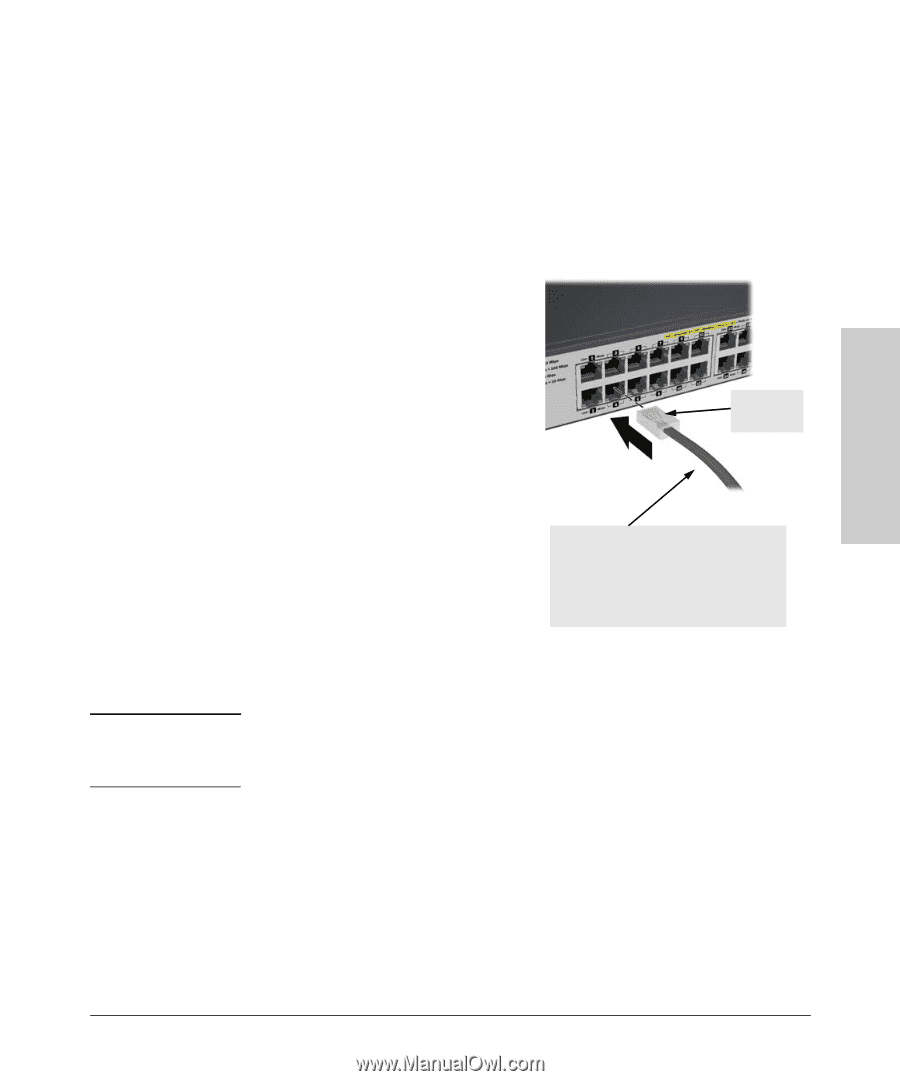
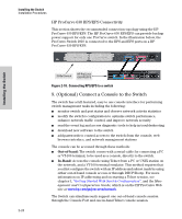
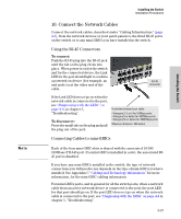
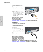
Note Installing the Switch Installation Procedures 10. Connect the Network Cables Connect the network cables, described under "Cabling Infrastructure" (page 2-5), from the network devices or your patch panels to the fixed RJ-45 ports on the switch or to any mini-GBICs you have installed in the switch. Using the RJ-45 Connectors To connect: Push the RJ-45 plug into the RJ-45 jack until the tab on the plug clicks into place. When power is on for the switch and for the connected device, the Link LED for the port should light to confirm a powered-on device (for example, an end node) is at the other end of the cable. RJ-45 connector If the Link LED does not go on when the network cable is connected to the port, see "Diagnosing with the LEDs" on page 4-4, in chapter 5, "Troubleshooting". To disconnect: Press the small tab on the plug and pull the plug out of the jack. Unshielded twisted-pair cable: • Category 3, 4, or 5 for 10 Mbps ports • Category 5 or better for 100 Mbps ports • Category 5e or better for 1000 Mbps ports Maximum distance: 100 meters Connecting Cables to mini-GBICs Each of the four mini-GBIC slots is shared with the associated 10/100/ 1000Base-T RJ-45 port. If a mini-GBIC is installed in a slot, the associated RJ45 port is disabled. If you have any mini-GBICs installed in the switch, the type of network connections you will need to use depends on the type of mini-GBICs you have installed. See Appendix C "Cabling and Technology Information" for more information, for the mini-GBIC cabling information. For mini-GBICs ports, and in general for all the switch ports, when a network cable from an active network device is connected to the port, the port LED for that port should go on. If the port LED does not go on when the network cable is connected to the port, see "Diagnosing with the LEDs" on page 4-4 in chapter 5, "Troubleshooting". 2-27 Installing the Switch
-
 1
1 -
2
-
3
-
4
-
5
-
6
-
7
-
8
-
9
-
10
-
11
-
12
-
13
-
14
-
15
-
16
-
17
-
18
-
19
-
20
-
21
-
22
-
23
-
24
-
25
-
26
-
27
-
28
-
29
-
30
-
31
-
32
-
33
-
34
-
35
-
36
-
37
-
38
-
39
-
40
-
41
-
42
-
43
-
44
-
45
-
46
-
47
-
 48
48 -
 49
49 -
 50
50 -
 51
51 -
 52
52 -
 53
53 -
 54
54 -
 55
55 -
 56
56 -
 57
57 -
 58
58 -
59
-
60
-
61
-
62
-
63
-
64
-
65
-
66
-
67
-
68
-
69
-
70
-
71
-
72
-
73
-
74
-
75
-
76
-
77
-
78
-
79
-
80
-
81
-
82
-
83
-
84
-
85
-
86
-
87
-
88
-
89
-
90
-
91
-
92
-
93
-
94
-
95
-
96
-
97
-
98
-
99
-
100
-
101
-
102
-
103
-
104
-
105
-
106
-
107
-
108
-
109
-
110
-
111
-
112
-
113
-
114
-
115
-
116
 |
 |