HP L6017tm Installation Instructions
HP L6017tm Manual
 |
View all HP L6017tm manuals
Add to My Manuals
Save this manual to your list of manuals |
HP L6017tm manual content summary:
- HP L6017tm | Installation Instructions - Page 1
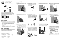
HP Retail RP7 VFD Customer Display Installation Instructions Installing the VFD 1. Slide down the two levers on the upper base, monitoring and diagnostic tools, go to www.hp.com/support. Localized Versions of this Document Localized versions of this document are available at www.hp.com for - HP L6017tm | Installation Instructions - Page 2
and, if not installed and used in accordance with the instructions, may cause harmful interference to radio communications. However, there comprising HP brand computers, keyboards and monitors that bear the "GS" approval mark, meet the applicable ergonomic requirements. The installation guides
-
 1
1 -
 2
2
 |
 |
HP Retail RP7 VFD
Customer Display
Installation Instructions
© Copyright 2012 Hewlett-Packard Development Company, L.P. The
information contained herein is subject to change without notice.The only
warranties for HP products and services are set forth in the express warranty
statements accompanying such products and services. Nothing herein should
be construed as constituting an additional warranty. HP shall not be liable
for technical or editorial errors or omissions contained herein.
Printed in
Second Edition: October 2012
691056-002
Before Your Begin
Before installing the vacuum fluorescent display (VFD), be sure to power
off the system and disconnect the power cord from the power outlet.
WARNING!
To avoid the risk of serious injury, ensure that the
power cord is unplugged from the electrical outlet at the wall
before installing the VFD. Failure to do so may expose you to the
risk of electric shock.
CAUTION:
To avoid the risk of damage to the system, ensure that
the power cord is unplugged from the electrical outlet at the wall
before installing the VFD.
Online Technical Support
For the online access to technical support information, self-solve tools,
online assistance, community forums or IT experts, broad multivendor
knowledge base, monitoring and diagnostic tools, go to
www.hp.com/support
.
Localized Versions of this Document
Localized versions of this document are available at
www.hp.com
for the following languages:
•
Simplified Chinese
•
Traditional Chinese
•
Bahasa Indonesian
•
Brazilian Portuguese
•
Spanish
•
Japanese
•
Korean
•
Thai
•
German
•
Italian
•
Dutch
•
English
•
French
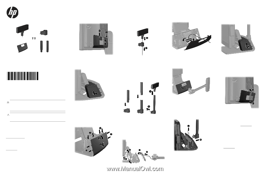
1.
Slide down the two levers on the upper corners
of the rear I/O panel
1
and rotate the cover off
2
.
2.
Pull the power supply cover back then lift it up
and off the unit.
3.
Remove the decorative panel from the rear of
the unit by gently prying the panel away from
the base at the tab locations on the top and
sides of the panel as indicated below
1
. Then
pull the top of the panel away from the base
2
and push straight down on the panel to release
the bottom tabs
3
.
4.
If you are installing the VFD with no poles
attached, assemble the VFD display by inserting
the VFD cable through the center of the
mounting bracket
1
and slide the VFD onto the
mounting bracket
2
.
5.
If you are installing the VFD with poles
attached, slide either one or two poles onto the
mounting bracket, depending on the desired
height of the VFD. Thread the VFD cable
through the top of the pole assembly and out
the bottom of the mounting bracket
1
, then
slide the VFD onto the pole assembly
2
.
6.
From the assembled pole, route the VFD cable
through the hole in the new decorative panel
1
that was included with the VFD, then through
the rear of the base
2
and out the front of the
base. Continue to route the extension cable up
through the cable retainer
3
and connect the
VFD cable to the 12V USB port on the RP7
4
.
7.
Wrap the excess extension cable around the
hooks on the rear of the base.
8.
Position the decorative plate onto the rear of the
base and press down to snap it in place.
9.
Slide the VFD mounting bracket into the
mounting hole on the rear of the RP7 base
1
,
and install the two screws included with the VFD
into the screw holes on top of the mounting
bracket
2
.
10.
Replace the power supply cover by lowering it
down over the neck of the base then sliding it
back until it snaps in place.
11.
Replace the rear I/O cover by placing the
hooks on the bottom of the cover into the slots
on the bottom of the chassis
1
. Then rotate the
top of the I/O cover up so that it snaps securely
onto the chassis
2
.
To configure the VFD, refer to the
HP Point of Sale
Configuration Guide
(available in English only). The
guide is available on the HP factory image of the RP7
system's hard drive and at www.hp.com
. To access
the guide on the factory image:
•
In Windows XP or Windows Embedded
POSReady 2009, select
Start
>
All Program
s >
HP Point of Sale Information
.
•
In Windows 7 or Windows Embedded
POSReady 7, select
Start
>
HP Point of Sale
Information
.
Check www.hp.com
for updated software or
documentation that became available between the
time your product was manufactured and delivered to
you.
Installing the VFD