HP LTE Notebook PC 5000 LTE 5000 Family of Personal Computers Maintenance and - Page 232
Expansion Base Feet, Bottom Cover Assembly, expansion base
 |
View all HP LTE Notebook PC 5000 manuals
Add to My Manuals
Save this manual to your list of manuals |
Page 232 highlights
2. Place the PC Card in the tracks with the card connector to the inside and label up. 3. Slide the card in until it seats. The door remains open while the card device is connected. Chapter 7.4 Expansion Base Feet The feet for the expansion base are rectangular, adhesive-backed rubber pads. Install the feet by removing the protective covering from the adhesive back and placing the feet in their positions on the bottom of the expansion base (Figure 7-8). Chapter 7.5 Bottom Cover Assembly The bottom cover assembly is spared as a unit and consists of: o Bottom cover o ISA expansion cover o Feet
-
 1
1 -
2
-
3
-
4
-
5
-
6
-
7
-
8
-
9
-
10
-
11
-
12
-
13
-
14
-
15
-
16
-
17
-
18
-
19
-
20
-
21
-
22
-
23
-
24
-
25
-
26
-
27
-
28
-
29
-
30
-
31
-
32
-
33
-
34
-
35
-
36
-
37
-
38
-
39
-
40
-
41
-
42
-
43
-
44
-
45
-
46
-
47
-
48
-
49
-
50
-
51
-
52
-
53
-
54
-
55
-
56
-
57
-
58
-
59
-
60
-
61
-
62
-
63
-
64
-
65
-
66
-
67
-
68
-
69
-
70
-
71
-
72
-
73
-
74
-
75
-
76
-
77
-
78
-
79
-
80
-
81
-
82
-
83
-
84
-
85
-
86
-
87
-
88
-
89
-
90
-
91
-
92
-
93
-
94
-
95
-
96
-
97
-
98
-
99
-
100
-
101
-
102
-
103
-
104
-
105
-
106
-
107
-
108
-
109
-
110
-
111
-
112
-
113
-
114
-
115
-
116
-
117
-
118
-
119
-
120
-
121
-
122
-
123
-
124
-
125
-
126
-
127
-
128
-
129
-
130
-
131
-
132
-
133
-
134
-
135
-
136
-
137
-
138
-
139
-
140
-
141
-
142
-
143
-
144
-
145
-
146
-
147
-
148
-
149
-
150
-
151
-
152
-
153
-
154
-
155
-
156
-
157
-
158
-
159
-
160
-
161
-
162
-
163
-
164
-
165
-
166
-
167
-
168
-
169
-
170
-
171
-
172
-
173
-
174
-
175
-
176
-
177
-
178
-
179
-
180
-
181
-
182
-
183
-
184
-
185
-
186
-
187
-
188
-
189
-
190
-
191
-
192
-
193
-
194
-
195
-
196
-
197
-
198
-
199
-
200
-
201
-
202
-
203
-
204
-
205
-
206
-
207
-
208
-
209
-
210
-
211
-
212
-
213
-
214
-
215
-
216
-
217
-
218
-
219
-
220
-
221
-
222
-
223
-
224
-
225
-
226
-
 227
227 -
 228
228 -
 229
229 -
 230
230 -
 231
231 -
 232
232 -
 233
233 -
 234
234 -
 235
235 -
 236
236 -
 237
237 -
238
-
239
-
240
-
241
-
242
-
243
-
244
-
245
-
246
-
247
-
248
-
249
-
250
-
251
-
252
-
253
-
254
-
255
-
256
-
257
-
258
-
259
-
260
-
261
-
262
-
263
-
264
-
265
-
266
-
267
-
268
-
269
-
270
-
271
-
272
-
273
-
274
-
275
-
276
-
277
-
278
-
279
-
280
-
281
-
282
-
283
-
284
-
285
-
286
-
287
-
288
-
289
-
290
-
291
-
292
-
293
-
294
-
295
-
296
-
297
-
298
-
299
-
300
-
301
-
302
-
303
-
304
-
305
-
306
-
307
-
308
-
309
-
310
-
311
-
312
-
313
-
314
 |
 |
2. Place the PC Card in the tracks with the card connector to the inside
and label up.
3. Slide the card in until it seats. The door remains open while the card
device is connected.
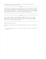
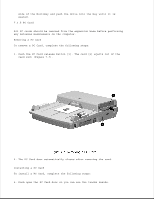
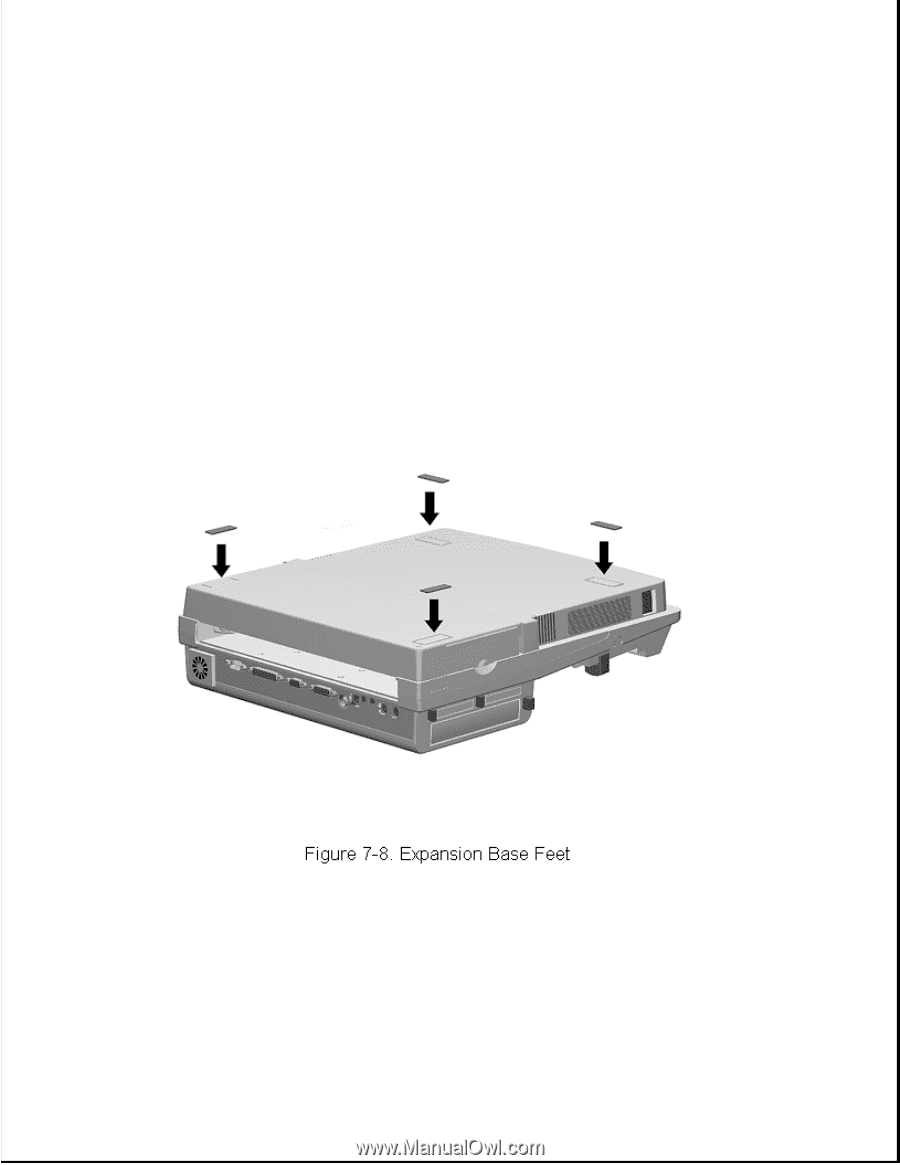
Chapter 7.4 Expansion Base Feet
The feet for the expansion base are rectangular, adhesive-backed rubber
pads. Install the feet by removing the protective covering from the
adhesive back and placing the feet in their positions on the bottom of the
expansion base (Figure 7-8).
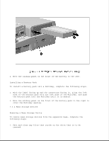
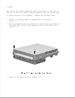
Chapter 7.5 Bottom Cover Assembly
The bottom cover assembly is spared as a unit and consists of:
o Bottom cover
o ISA expansion cover
o Feet