HP LTE Notebook PC 5280 LTE 5000 Family of Personal Computers Maintenance and - Page 185
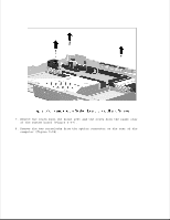
Preparing the MultiBay Expansion Base for Disassembly, Remove any PC Cards
 |
View all HP LTE Notebook PC 5280 manuals
Add to My Manuals
Save this manual to your list of manuals |
Page 185 highlights
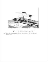
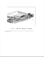
Chapter 6.3 Preparing the MultiBay Expansion Base for Disassembly NOTE: It is important that these instructions be followed when installing a new expansion base top cover (Service Spare Part Number 213711-003). 1. Do not remove the plastic hole cover. 2. Discard the fan. Before beginning removal and replacement procedures, complete the following steps: 1. Undock the computer from the expansion base (Section 5.3.1). 2. Disconnect AC power and any external devices (Section 6.3.1). 3. Remove the battery pack(s) (Section 6.3.2). 4. Remove the mass storage devices (Section 6.3.3). 5. Remove any PC Cards (section 6.3.4).
-
 1
1 -
2
-
3
-
4
-
5
-
6
-
7
-
8
-
9
-
10
-
11
-
12
-
13
-
14
-
15
-
16
-
17
-
18
-
19
-
20
-
21
-
22
-
23
-
24
-
25
-
26
-
27
-
28
-
29
-
30
-
31
-
32
-
33
-
34
-
35
-
36
-
37
-
38
-
39
-
40
-
41
-
42
-
43
-
44
-
45
-
46
-
47
-
48
-
49
-
50
-
51
-
52
-
53
-
54
-
55
-
56
-
57
-
58
-
59
-
60
-
61
-
62
-
63
-
64
-
65
-
66
-
67
-
68
-
69
-
70
-
71
-
72
-
73
-
74
-
75
-
76
-
77
-
78
-
79
-
80
-
81
-
82
-
83
-
84
-
85
-
86
-
87
-
88
-
89
-
90
-
91
-
92
-
93
-
94
-
95
-
96
-
97
-
98
-
99
-
100
-
101
-
102
-
103
-
104
-
105
-
106
-
107
-
108
-
109
-
110
-
111
-
112
-
113
-
114
-
115
-
116
-
117
-
118
-
119
-
120
-
121
-
122
-
123
-
124
-
125
-
126
-
127
-
128
-
129
-
130
-
131
-
132
-
133
-
134
-
135
-
136
-
137
-
138
-
139
-
140
-
141
-
142
-
143
-
144
-
145
-
146
-
147
-
148
-
149
-
150
-
151
-
152
-
153
-
154
-
155
-
156
-
157
-
158
-
159
-
160
-
161
-
162
-
163
-
164
-
165
-
166
-
167
-
168
-
169
-
170
-
171
-
172
-
173
-
174
-
175
-
176
-
177
-
178
-
179
-
 180
180 -
 181
181 -
 182
182 -
 183
183 -
 184
184 -
 185
185 -
 186
186 -
 187
187 -
 188
188 -
 189
189 -
 190
190 -
191
-
192
-
193
-
194
-
195
-
196
-
197
-
198
-
199
-
200
-
201
-
202
-
203
-
204
-
205
-
206
-
207
-
208
-
209
-
210
-
211
-
212
-
213
-
214
-
215
-
216
-
217
-
218
-
219
-
220
-
221
-
222
-
223
-
224
-
225
-
226
-
227
-
228
-
229
-
230
-
231
-
232
-
233
-
234
-
235
-
236
-
237
-
238
-
239
-
240
-
241
-
242
-
243
-
244
-
245
-
246
-
247
-
248
-
249
-
250
-
251
-
252
-
253
-
254
-
255
-
256
-
257
-
258
-
259
-
260
-
261
-
262
-
263
-
264
-
265
-
266
-
267
-
268
-
269
-
270
-
271
-
272
-
273
-
274
-
275
-
276
-
277
-
278
-
279
-
280
-
281
-
282
-
283
-
284
-
285
-
286
-
287
-
288
-
289
-
290
-
291
-
292
-
293
-
294
-
295
-
296
-
297
-
298
-
299
-
300
-
301
-
302
-
303
-
304
-
305
-
306
-
307
-
308
-
309
-
310
-
311
-
312
-
313
-
314
 |
 |

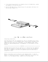
Chapter 6.3 Preparing the MultiBay Expansion Base for Disassembly
NOTE: It is important that these instructions be followed when installing
a new expansion base top cover (Service Spare Part Number
213711-003).
1. Do not remove the plastic hole cover.
2. Discard the fan.
Before beginning removal and replacement procedures, complete the
following steps:
1. Undock the computer from the expansion base (Section 5.3.1).
2. Disconnect AC power and any external devices (Section 6.3.1).
3. Remove the battery pack(s) (Section 6.3.2).
4. Remove the mass storage devices (Section 6.3.3).
5. Remove any PC Cards (section 6.3.4).