HP LaserJet 9000 Service Manual
HP LaserJet 9000 Manual
 |
View all HP LaserJet 9000 manuals
Add to My Manuals
Save this manual to your list of manuals |
HP LaserJet 9000 manual content summary:
- HP LaserJet 9000 | Service Manual - Page 1
HP LaserJet 9000/9040/9050 Service Manual - HP LaserJet 9000 | Service Manual - Page 2
- HP LaserJet 9000 | Service Manual - Page 3
HP LaserJet 9000, 9040, and 9050 Series printers Service - HP LaserJet 9000 | Service Manual - Page 4
Copyright and License © 2005 Copyright Hewlett-Packard Development Company, LP Reproduction, adaptation or translation without prior products and services. Nothing herein should be construed as constituting an additional warranty. HP shall not be liable for technical or editorial errors or omissions - HP LaserJet 9000 | Service Manual - Page 5
information Product features of the HP LaserJet 9000 Series printers 2 Product features of the HP LaserJet 9040/9050 Series printers 4 Product specifications 6 Product overview 10 External view of the printer and accessories 10 Interface connections 11 Optional accessories 12 Regulatory - HP LaserJet 9000 | Service Manual - Page 6
firmware to a single printer 55 4 Product maintenance Preventative maintenance 60 Preventive maintenance kit contents 60 Cleaning the printer and accessories 61 General cleaning 61 Internal cleaning 62 Fuser cleaning 65 Print cartridge information 67 Storage 67 Handling instructions - HP LaserJet 9000 | Service Manual - Page 7
unit (PIU 126 Registration assembly 129 Transfer-guide assembly 131 Left assemblies 133 Duplexer 133 Fuser assembly 134 Back assemblies 135 Formatter 135 Low-voltage power supply 136 High-voltage power supply 137 DC controller 138 Toner-sensor contact assembly 140 Drum motor 141 Feed - HP LaserJet 9000 | Service Manual - Page 8
179 Alphabetical error messages 180 Numerical error messages 188 User- and service-level diagnostics 213 Paper-path test 213 Service test 213 Service-level diagnostics 215 Engine test 215 Service menu 215 Diagnostics flowchart 216 Other diagnostics for the HP LaserJet 9000, 9000mfp, and - HP LaserJet 9000 | Service Manual - Page 9
problem source: media or printer 244 Isolate a paper path 244 Isolate a media brand 245 Isolate a media type 245 Communication troubleshooting 246 Communications check 246 Jetdirect configuration 246 Embedded LAN troubleshooting (HP LaserJet 9040n/9050n, HP LaserJet 9040dn/9050dn, HP LaserJet - HP LaserJet 9000 | Service Manual - Page 10
Index viii Table of contents - HP LaserJet 9000 | Service Manual - Page 11
of the HP LaserJet 9000 Series printers 2 Table 2. Features of the HP LaserJet 9040/9050 Series printers 4 Table 3. Configuration comparison 6 Table 4. Physical specifications 7 Table 5. Electrical specifications (HP LaserJet 9000 7 Table 6. Electrical specifications (HP LaserJet 9040 8 Table - HP LaserJet 9000 | Service Manual - Page 12
Table 50. Tray 4 main body (2 of 2 287 Table 51. Tray 4 drive assembly 288 Table 52. Tray 4 PCA location 289 Table 53. Tray 1 assembly 290 Table 54. Alphabetical parts list 291 Table 55. Numerical parts list 296 x List of tables - HP LaserJet 9000 | Service Manual - Page 13
connections (HP LaserJet 9040/9050 Series printer) . . . . . 11 Figure 4. Interface connections (HP LaserJet 9000 Series printer 11 Figure 5. Optional accessories 12 Figure 6. Space requirements for the base model 17 Figure 7. Space requirements with a finishing device (3,000-sheet stapler - HP LaserJet 9000 | Service Manual - Page 14
Figure 73. Transfer-guide assembly 131 Figure 74. Reinstalling the transfer-guide assembly 132 Figure 75. Duplexer (1 of 2 133 Figure 76. Duplexer (2 of 2 133 Figure 77. Fuser assembly (1 of 2 134 Figure 78. Fuser assembly (2 of 2 134 Figure 79. Formatter (HP LaserJet 9000 shown 135 Figure - HP LaserJet 9000 | Service Manual - Page 15
of 2 162 Figure 116. Pickup assembly (2 of 2 162 Figure 117. Paper-connecting unit 163 Figure 118. Basic troubleshooting process flow (1 of 2 168 Figure 119. Basic troubleshooting process flow (2 of 2 169 Figure 120. Sample event log (HP LaserJet 9000 series printer page shown) 176 Figure 121 - HP LaserJet 9000 | Service Manual - Page 16
xiv List of figures - HP LaserJet 9000 | Service Manual - Page 17
Chapter contents Product features of the HP LaserJet 9000 Series printers 2 Product features of the HP LaserJet 9040/9050 Series printers 4 Product specifications 6 Product overview 10 External view of the printer and accessories 10 Interface connections 11 Optional accessories 12 Regulatory - HP LaserJet 9000 | Service Manual - Page 18
HP LaserJet 9000hns printer contains the HP LaserJet 9000dn with a 2,000sheet feeder (optional tray 4) and an optional 3,000-sheet stapler/stacker, an optional 3,000-sheet stacker, or an optional multifunction finisher. Table 1. Features of the HP LaserJet 9000 Series printers Speed z 50 pages - HP LaserJet 9000 | Service Manual - Page 19
1. Features of the HP LaserJet 9000 Series printers (continued) Expandability Wireless printing Interface connection Networking Duty cycle All models accept the following accessories: z Optional tray 1, a 100-sheet or 10-envelope multipurpose tray for automatic and manual feeding of envelopes - HP LaserJet 9000 | Service Manual - Page 20
sheet multipurpose tray (tray 1), an embedded HP Jetdirect print server, and a duplex printing accessory (duplexer) for printing on both sides of paper. Table 2. Features of the HP LaserJet 9040/9050 Series printers Speed z 40 pages per minute (ppm) (HP LaserJet 9040 series printer) or 50 ppm (HP - HP LaserJet 9000 | Service Manual - Page 21
2. Features of the HP LaserJet 9040/9050 Series printers (continued) Expandability Wireless printing Interface connection Networking Duty cycle All models accept the following accessories: z Optional tray 1, a 100-sheet or 10-envelope multipurpose tray for automatic and manual feeding of envelopes - HP LaserJet 9000 | Service Manual - Page 22
HP HP HP HP LaserJet LaserJet LaserJet LaserJet 9000 9000n 9000dn 9000hns Standard memory 64 MB Maximum memory 384 MB 64 MB 384 MB 64 MB 384 MB 64 MB 384 MB PS emulation Standard Standard Standard Standard Jetdirect print server Optional Standard Standard Standard Optional duplexer - HP LaserJet 9000 | Service Manual - Page 23
lb) (without print cartridge) 9000n/9040n/9050n: 69.4 kg (153 lb) 9000dn/9040dn/9050dn: 76.2 kg (168 lb) 76.2 kg (168 lb) Table 5. Electrical specifications (HP LaserJet 9000) Volts Frequency Amperes (A) Watts (W) (typical) Thermal units per hour (BTu/hr) 100-127 Vac 50/60 Hz ± 10% ± 2 Hz - HP LaserJet 9000 | Service Manual - Page 24
.56 BTu/hr PowerSave 2 = 85.35 BTu/hr off = 0.69 BTu/hr Table 7. Electrical specifications (HP LaserJet 9050) Volts Frequency Ampres Watts (W) (typical) Thermal units per hour (BTu/hr) 100-127 Vac ± 50/60 Hz 10% ± 2 Hz Minimum recommended current capacity = 12 A dedicated circuit printing - HP LaserJet 9000 | Service Manual - Page 25
Table 9. Acoustical specifications Declared per ISO 9296 Sound power level1 HP LaserJet 9050 Sound power level2 HP LaserJet 9040 Printing (50 ppm) Ready hp.com/support/ lj9050_lj9040 for current information. 3.Values current as of October 16, 2003. Values subject to change, see www.hp.com/support - HP LaserJet 9000 | Service Manual - Page 26
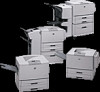
Product overview External view of the printer and accessories Face-up bin Optional 3,000-sheet stapler/stacker, 3,000sheet stacker, 8-bin mailbox, or multifunction finisher Front door Duplexer (inside the printer) Left door (behind the output Tray 2 Tray 3 Optional tray 4 Standard output bin (face- - HP LaserJet 9000 | Service Manual - Page 27
LaserJet 9040/9050 Series printer) Parallel connector Figure 4. I/O slots HP Jetdirect print server (optional) Foreign interface connector (not used) HP Fast InfraRed Connect (optional IR pod) HP Jet-Link connector (optional accessories connection) Interface connections (HP LaserJet 9000 Series - HP LaserJet 9000 | Service Manual - Page 28
Multifunction finisher 3,000-sheet stapler/stacker 3,000-sheet stacker Tray 1 Duplex printing accessory (duplexer) Figure 5. 8-bin mailbox (HP LaserJet 9040/9050 Series printer only) Optional accessories Tray 4 HP Fast InfraRed Connect (HP LaserJet 9000 Series printer only 12 Chapter - HP LaserJet 9000 | Service Manual - Page 29
information and requirements, please see the HP LaserJet 9000 Start Guide or the HP LaserJet 9040/9050 Start Guide. FCC regulations For FCC regulations, please see the HP LaserJet 9000 Start Guide or the HP LaserJet 9040/9050 Start Guide. Declaration of conformity For declaration of conformity - HP LaserJet 9000 | Service Manual - Page 30
(49 7031) 142253 Exchange program Hewlett-Packard offers remanufactured assemblies for some parts. These are identified in "Illustrations and parts lists" in chapter 8, and can be ordered through HPS. Consumables The printer has two consumables: the print cartridge and the preventive maintenance kit - HP LaserJet 9000 | Service Manual - Page 31
2 Product requirements Chapter contents Site requirements 16 Operating environment 16 Space requirements 17 Media specifications 19 Guidelines for selecting print media 19 Special media specifications 19 Storing print media 22 Media input/output options 25 Trays, bins, and paper handling 25 - HP LaserJet 9000 | Service Manual - Page 32
to ensure the proper operation of this printer. See "Product specifications" in chapter 1. Consider the following points before installing the printer: z Install in a well-ventilated, dust-free area. z Install on a level, flat surface that can support the printer size and weight. Make sure that all - HP LaserJet 9000 | Service Manual - Page 33
368 mm 633 mm (24.9 inches) (17.8 inches) Space requirements 353 mm (13.9 inches) 638 mm (25.1 inches) 353 mm (13.9 inches) 638 mm (25.1 inches) Figure 6. Space requirements for the base model 600 mm (23.6 inches) Site requirements 17 - HP LaserJet 9000 | Service Manual - Page 34
2,591 mm (102 inches) 1,001 mm (39.4 inches) 2,591 mm (102 inches) 1,036 mm (40.8 inches) Figure 7. Space requirements with a finishing device (3,000-sheet stapler/stacker shown) and tray 4 installed 18 Chapter 2 Product requirements - HP LaserJet 9000 | Service Manual - Page 35
it meets the requirements that are specified in this service manual and in the HP LaserJet Printer Family Print Media Guide. See "Media input/output options" on page 25. Always test print media before buying large quantities. Hewlett-Packard neither warrants nor recommends the use of a particular - HP LaserJet 9000 | Service Manual - Page 36
. The extra flaps and strips might cause wrinkling, creasing, or jams, and can even damage the fuser. Label specifications To avoid damaging the printer, use only labels that are recommended for laser printers. Never print on the same sheet of labels more than once and never print on a partial - HP LaserJet 9000 | Service Manual - Page 37
Many preprinted forms and special letterhead papers perform well in HP LaserJet printers. However, these papers undergo processes that alter their original characteristics, and care must be taken to ensure that they conform to HP specifications. All special papers should be wrapped in moistureproof - HP LaserJet 9000 | Service Manual - Page 38
problems in the fuser and transfer areas of HP LaserJet printers. The surface resistivity and moisture content can be greatly altered, resulting in print-quality problems. Hard surface coatings increase wear on the rollers and media guides. All chemically treated media must meet HP specifications - HP LaserJet 9000 | Service Manual - Page 39
in its moisture-proof wrapping. If the printer environment is subject to extremes, unwrap only the approximate equivalent points in weight specifications other than U.S. bond weight 29 35 39 64 Japan metric weight (g/m2) 64 20 50 28 34 42 46 75 75 21 54 30 36 44 49 80 80 22 - HP LaserJet 9000 | Service Manual - Page 40
Note Table 10. Paper weight equivalence U.S. postcard thickness (mm) 0.23 U.S. bond weight (lb) U.S. text/ book weight (lb) U.S. cover weight (lb) U.S. bristol U.S. index weight (lb) weight (lb) U.S. tag weight (lb) Europe metric weight (g/m2) 47 119 65 80 97 108 176 53 134 74 90 - HP LaserJet 9000 | Service Manual - Page 41
does not meet HP specifications might cause problems for the printer, requiring repair. Such repair is not covered by the Hewlett-Packard warranty or service agreements. The HP LaserJet 9000 Series printers and HP LaserJet 9040/9050 Series printers accept a variety of media, such as cut-sheet paper - HP LaserJet 9000 | Service Manual - Page 42
Supported sizes of paper for input and output For more information on an optional HP output device, see the user guide that came with the product. Tray or Bin Capacity Paper Weight Optional tray 1 Up to 100 sheets 64 to 199 g/m2 (17- to 53-lb bond) Standard top bin Up to 500 sheets Up to 50 - HP LaserJet 9000 | Service Manual - Page 43
Standard undetectable sizes: 8K, 16K Custom sizes Custom types: Duplexing is not supported for envelopes, labels, or transparencies. 64 to 199 g/m2 (17- to 53-lb bond) Optional 3,000-sheet stacker Up to 3,000 sheets of Letter or A4 Up to 1,500 sheets of A3 or 11 x 17 Standard sizes for lower bin - HP LaserJet 9000 | Service Manual - Page 44
(17- to 53-lb bond) in lower booklet bin 64 to 216 g/m2 (17- to 58-lb bond) in upper bin Up to 40 booklets of 5 sheets, stacked; or 20 booklets of 10, sheets stacked Optional 8-bin mailbox (HP LaserJet 9040/9050 Series printers only) Up to 250 sheets of A4 or Letter in each output bin Standard - HP LaserJet 9000 | Service Manual - Page 45
job menu 38 Information menu 38 Paper-handling menu 39 System setup submenu 46 I/O submenu 48 Resets submenu 53 Diagnostics menu 54 Service menu 54 Remote firmware upgrade (RFU 55 Upgrading firmware to a single printer 55 HP Web Jetadmin 6.1 for a single printer 57 Chapter contents 29 - HP LaserJet 9000 | Service Manual - Page 46
four lines of text. The control panel graphical display provides both status and error messages by using distinct text and codes. GRAPHICAL DISPLAY PAUSE/RESUME (FOR 9000 SERIES) MENU (FOR 9040/9050 SERIES) CANCEL JOB (FOR 9000 SERIES) STOP (FOR 9040/9050 SERIES) Figure 11. READY DATA ATTENTION - HP LaserJet 9000 | Service Manual - Page 47
between pause and resume. MENU NUMERIC KEYPAD z Opens or exits the menus. z Specifies numeric values. The HP LaserJet 9000 and the HP LaserJet 9040/9050 Series printers are similar products. The behavior or feature is common in both printers unless noted otherwise. Using the control panel 31 - HP LaserJet 9000 | Service Manual - Page 48
number and then presses . The following table outlines what happens in certain printer states when a button on the numeric keypad is pressed. Table 12. Printer state and numeric key effect PowerSave Idle/pause Continuable Data error Exit the PowerSave mode. Open a menu. No effect. Each menu has - HP LaserJet 9000 | Service Manual - Page 49
Control-panel defaults are the values that are specified by selecting a control-panel item and pressing . An asterisk ( * ) next to the item name indicates that it is now the default. The printer retains default default symbol set for the specific language. For all other languages, the default - HP LaserJet 9000 | Service Manual - Page 50
Figure 12. Registration page (1 of 2) 34 Chapter 3 Product configuration - HP LaserJet 9000 | Service Manual - Page 51
Figure 13. Registration page (2 of 2) Settings and defaults 35 - HP LaserJet 9000 | Service Manual - Page 52
Printer driver information When you change a setting from the printer control panel, the new setting becomes the default value. You can override any control-panel setting from the printer driver and through most software programs. 36 Chapter 3 Product configuration - HP LaserJet 9000 | Service Manual - Page 53
error or one of the following messages: z READY, if the printer is online z OFFLINE, if the printer is offline Items appear only when the associated optional accessory is installed or the associated function is activated. Printer-driver and software commands override the printer control-panel - HP LaserJet 9000 | Service Manual - Page 54
menu map that shows the layout and current settings of the control-menu items. The printer will back up one screen to SET FRONT TO BACK when page is completed. PRINT PCL FONT LIST Generates a typeface list of all PCL fonts that are available on the printer. The printer will return to the online - HP LaserJet 9000 | Service Manual - Page 55
(such as duplex and manual feed) are available from specific software programs, or from the printer driver (if the appropriate driver is installed). Printer-driver and softwareprogram settings override control-panel settings. Item Values Explanation TRAY 1=FIRST (HP LaserJet 9000 only) FIRST - HP LaserJet 9000 | Service Manual - Page 56
Item Values Explanation FUSER MODES (HP LaserJet 9000 only) List of print-media types Configure the fuser mode that is associated with each media type. The default value for each paper type is AUTO. The fuser mode can only be changed from this menu option on the control panel. AUTO: Utilizes - HP LaserJet 9000 | Service Manual - Page 57
to select the number of copies. Note It is best to set the number of copies from the printer driver or software program. (Driver and software settings override control-panel settings.) DEFAULT PAPER SIZE= LETTER LETTER LEGAL A4 EXECUTIVE 11X17 A3 B4(JIS) B5(JIS) CUSTOM A5 LETTER ROTATED STATEMENT - HP LaserJet 9000 | Service Manual - Page 58
control-panel display. Turn the edge-to-edge mode on or off for all print jobs. This mode can be overridden inside a print job by using an edge-to-edge PJL variable. Select the version of Courier font to use: REGULAR: The internal Courier font that is available on the HP LaserJet 4 Series printers - HP LaserJet 9000 | Service Manual - Page 59
default page orientation. Note It is best to set the page orientation from the printer driver or software program. (Driver and software settings override control PCL jobs (pure text, no job control). Some environments, such as UNIX®, indicate a new line by using only the line-feed control code. - HP LaserJet 9000 | Service Manual - Page 60
on the back. SOURCE=TRAY 2 ADJUST TRAY FUSER MODES (HP LaserJet 9040/9050 only) List of media types Configure the fuser mode that is associated with each print-media type. The fuser mode can only be changed from this menu option on the control panel. The default value for each paper type is - HP LaserJet 9000 | Service Manual - Page 61
the default setting of 3 usually produces the best results. Note It is best to change the toner density from the driver or software program. (Driver and software settings override control-panel settings.) When printing on narrow media, this setting slows down the printer which stabilizes the fuser - HP LaserJet 9000 | Service Manual - Page 62
. The values for this menu item are ENABLED (default) and DISABLED. SLEEP DELAY=90 MINUTES POWERSAVE TIME=1 HOUR (HP LaserJet 9000 only) 1 MINUTE 15 MINUTES 30 MINUTES 60 MINUTES 90 MINUTES 2 HOURS 4 HOURS Set how long the printer remains idle before it enters Sleep mode. The Sleep mode minimizes - HP LaserJet 9000 | Service Manual - Page 63
=AUTO AUTO PCL PS PDF XHTML MIME CLEARABLE ON WARNINGS= JOB JOB AUTO CONTINUE=ON ON OFF CARTRIDGE LOW= CONTINUE CONTINUE STOP CARTRIDGE OUT= CONTINUE (HP LaserJet 9040/9050 only) STOP CONTINUE JAM RECOVERY= AUTO AUTO ON OFF Explanation Select the default printer language (personality - HP LaserJet 9000 | Service Manual - Page 64
Item Values RAM DISK=AUTO (HP LaserJet 9000 only) AUTO OFF LANGUAGE=ENGLISH List of available languages Explanation This item determines how the RAM disk is configured. This item appears only if no optional hard disk is installed and the printer has at least 8 MB of memory. OFF: The RAM disk - HP LaserJet 9000 | Service Manual - Page 65
on the particular accessory product that is installed. If the printer contains an HP Jetdirect print server EIO card, you can configure basic networking EIO menu. These and other parameters can also be configured through HP Web Jetadmin or other network configuration tools (such as by using Telnet - HP LaserJet 9000 | Service Manual - Page 66
Embedded Jetdirect submenu (HP LaserJet 9040n/9050n and 9040dn/9050dn only) Item TCP/ MANUAL SETTINGS IP ADDRESS The unique IP address of the printer. SUBNET MASK The subnet mask for the printer. SYSLOG SERVER The IP address of the syslog server that receives and logs syslog messages. DEFAULT - HP LaserJet 9000 | Service Manual - Page 67
SECURE WEB Options Values DEFAULT IP AUTO IP LEGACY PRIMARY DNS SECONDARY . DNS PROXY SERVER PROXY 64 characters. For some networks, you might need to contact your Independent Service Provider (ISP) for the proxy server address. Type the port number that the proxy server uses for client support - HP LaserJet 9000 | Service Manual - Page 68
in bytes, to be sent to the remote host. The minimum is 64 (default) and the maximum is 2,048. Specify the length of time, in seconds, to wait for a response from the remote host. The default is 1 and the maximum is 100. Specify the number of ping test packets to - HP LaserJet 9000 | Service Manual - Page 69
the following circumstances: z You want to restore the printer default settings. z Communication between the product and computer has been interrupted. z You are having problems with a port. The items in the Resets submenu clear all memory in the printer, while RESET clears only the current job - HP LaserJet 9000 | Service Manual - Page 70
list of the 50 most recent entries in the error log. The printed event log shows error number, page count, error code, and description or personality. SHOW EVENT LOG Allows the user to scroll through the contents of the event log from the printer control panel, and shows the 50 most recent events - HP LaserJet 9000 | Service Manual - Page 71
firmware installed on the printer. 2 Go to the www.hp.com/go/lj9000_firmware, www.hp.com/go/lj9040_firmware, or www.hp.com/go/lj9050_firmware Web site and download the latest firmware. 3 Download the new firmware to the printer depends on the specific hardware configuration of the printer, such as - HP LaserJet 9000 | Service Manual - Page 72
If the HP LaserJet printer uses a direct network connection, file transfer protocol (FTP) can be used to update the HP LaserJet firmware following password, press ENTER for each. 6 Type BIN at the >prompt. 7 Press ENTER. 8 Type:put where is the location where the .RFU was downloaded - HP LaserJet 9000 | Service Manual - Page 73
Printers, and then click Continue. 6 Under Upload new firmware image:, click Browse to locate the .RFU file you that downloaded from the www.hp.com/go/lj9000_firmware, www.hp.com/go/lj9040_firmware, or the www.hp Go. 3 In the Device List, select the printers that you want to include in the group, and - HP LaserJet 9000 | Service Manual - Page 74
6 When prompted for the type of update to perform, click Update Printers, and then click Continue. 7 From the list of HP Devices, select the printers to be upgraded, or click Select All. 8 Click Update to install the new printer firmware. 58 Chapter 3 Product configuration - HP LaserJet 9000 | Service Manual - Page 75
Chapter contents Preventative maintenance 60 Preventive maintenance kit contents 60 Cleaning the printer and accessories 61 General cleaning 61 Internal cleaning 62 Fuser cleaning 65 Print cartridge information 67 Storage 67 Handling instructions 67 Refilled print cartridges 68 Print - HP LaserJet 9000 | Service Manual - Page 76
in the preventive maintenance kit: z Fuser assembly (1 assembly) z Transfer roller assembly (1 assembly) z Feed specifications" in chapter 2 or the HP LaserJet Printer Family Print Media Guide for information about suitable media, environment, and usage conditions. 60 Chapter 4 Product maintenance - HP LaserJet 9000 | Service Manual - Page 77
print cartridge). Skin oils on the roller can cause print-quality problems. To prevent damage, do not expose the print cartridge to direct toner to set permanently into clothing. Vacuum specifications Do not use a conventional vacuum to vacuum the printer or any spilled toner. The toner particles - HP LaserJet 9000 | Service Manual - Page 78
problems such as toner specks or smearing. Internal cleaning can assist in correcting and preventing these types of problems. Before you begin these steps, turn the printer position, and then slide the print cartridge out of the printer. Figure 15. Remove the print cartridge CAUTION To prevent - HP LaserJet 9000 | Service Manual - Page 79
5 Press the button on the green lever, and then turn the lever clockwise to the locked position. Figure 18. Lock the print cartridge Cleaning the printer and accessories 63 - HP LaserJet 9000 | Service Manual - Page 80
6 Close the front cover. Plug in all of the power cords, and then turn on the printer. Figure 19. Close the front cover 64 Chapter 4 Product maintenance - HP LaserJet 9000 | Service Manual - Page 81
page cleans the excess toner off the pressure roller in the fuser. The page contains instructions that walk the customer instructions indicate that the page be placed face-up in tray 2. The customer is then instructed to select the PROCESS CLEANING PAGE on the control the printer and accessories 65 - HP LaserJet 9000 | Service Manual - Page 82
down in tray 1, or face-up in tray 2, the customer is instructed to select this menu item to complete the cleaning process. The device processed, CLEANING appears on the display panel. When toner is cleaned from inside the printer, shiny black spots appear on the black strip. Product maintenance - HP LaserJet 9000 | Service Manual - Page 83
installed. Excessive vibration during shipping can cause toner to leak, contaminating the printer. Never expose the print cartridge to direct sunlight, or to room light. Bright light and direct sunlight can permanently damage a print cartridge. Handling instructions z Do not touch the surface of - HP LaserJet 9000 | Service Manual - Page 84
setting, and EconoMode off (default settings). Saving toner by using EconoMode HP LaserJet 9000/9040/9050 print cartridge usage can be extended by using the printer EconoMode feature. EconoMode can be turned on or off through the driver or through HP LaserJet device configuration. z Some software - HP LaserJet 9000 | Service Manual - Page 85
on sequence 73 Timing chart 74 Engine control system 75 DC controller PCA 76 DC controller operations 77 High-voltage power supply circuit prevention 87 Overhead-transparency detection 87 Fuser-wrapping-jam detection 87 Jam detection 88 Tray 1 93 Tray 1 driver PCA 93 Power supply 93 - HP LaserJet 9000 | Service Manual - Page 86
Basic operation This chapter provides information about the following systems: z Engine control z Formatter z Laser/scanner z Image formation z Pickup and feed Relationships among the five systems are represented in figure 21. Figure 21. Printer systems 70 Chapter 5 Theory of operation - HP LaserJet 9000 | Service Manual - Page 87
Cartridge check Cartridge-memory check for toner level Optional interface communication (duplexer, tray 1, tray 4, paper handling) Cassette checks (lifting and loading status) Jam check (auto flush/eject) Fuser-wrapping-jam detect Door open/sleep check Fuser-roller temperature control and delivery - HP LaserJet 9000 | Service Manual - Page 88
the input of a print z command until the primary dc z bias is turned off z z z z z control completion fuser control (print to standby temperature-180°C [356°F]) fan motor control (fan 1 through 6 full-speed rotation) fuser/delivery, drum, and scanner motor stop (writes in cartridge memory - HP LaserJet 9000 | Service Manual - Page 89
control, fuser control, fuser/ printer flushes any residual paper from the paper path. 6 A cartridge-presence check occurs. 7 A cartridge-memory check occurs. 8 Any installed accessories are initialized. 9 The fuser toner-level detection). 15 The fuser reaches its target temperature. 16 The fuser - HP LaserJet 9000 | Service Manual - Page 90
Timing chart Figure 23. Timing chart block diagram 74 Chapter 5 Theory of operation - HP LaserJet 9000 | Service Manual - Page 91
system coordinates the laser/scanner, image formation, and pickup and feed systems according to the instructions it receives from the formatter. The engine control system consists of the DC controller PCA, the high-voltage power supply circuit, and the low-voltage power supply unit. Figure 24 - HP LaserJet 9000 | Service Manual - Page 92
DC controller PCA The DC controller circuit controls operational sequences of the printer. Figure 25. DC controller PCA block diagram 76 Chapter 5 Theory of operation - HP LaserJet 9000 | Service Manual - Page 93
motor, and fan motor 6 • Communication with the duplexer and tray 1, if installed • Fuser heater control circuit and fuser heater safety circuit z The ASIC (IC202) on the DC controller PCA controls the following printer operations, according to instructions from the CPU: • laser/scanner • rotation - HP LaserJet 9000 | Service Manual - Page 94
upper guide, the transfer charging roller, the separation static charge eliminator, and the pressure roller through the ASIC (IC 202), according to instructions it receives from the CPU (IC201) on the DC controller PCA. The high-voltage power supply circuit also detects the toner level. Figure - HP LaserJet 9000 | Service Manual - Page 95
of the bias generation circuits has a specific purpose: z Primary charging bias generation. Applies bias to the primary charging roller to spread a uniform, negative charge on the photosensitive drum. z Developing bias generation. Controls the amount of toner transferred onto latent images formed on - HP LaserJet 9000 | Service Manual - Page 96
fuser printer is turned on. The ac power is converted as follows: z +24 Vdc for motors, solenoids, clutches, and the high-voltage power supply circuit z +5 Vdc for the laser/scanner PCA, the beam detect PCA, and the formatter z +3.3 Vdc for the formatter, sensors, and the ICs on the DC controller - HP LaserJet 9000 | Service Manual - Page 97
. z Flash memory card (HP LaserJet 9040/9050 only)-The formatter has three flash memory card slots. One slot is dedicated to printer firmware. The printer supports Type 1 and Type 2 flash memory. Unlike standard printer memory, flash memory cards can be used to permanently store downloaded fonts - HP LaserJet 9000 | Service Manual - Page 98
if you want to reformat the flash memory card appears on the control-panel display. If you choose to reformat the card, all data on the card will be lost. z Real Time Clock (HP LaserJet 9040/9050 only)-The user sets the date and time when the printer is turned on for the first time - HP LaserJet 9000 | Service Manual - Page 99
/scanner unit of the HP LaserJet 9000 series printer and the HP LaserJet 9040/9050 series printer contains two laser diodes in its laser unit. The printer employs the "twin-beam method," which scans two lines simultaneously. Based on signals it receives from the DC controller and the formatter, the - HP LaserJet 9000 | Service Manual - Page 100
transfer charging roller, and fuser. When a print command is sent from the formatter, the engine controller drives the main motor to by rubbing against the developing cylinder which is connected to a negative dc supply. The negatively charged toner is attracted to the discharged (exposed, grounded) - HP LaserJet 9000 | Service Manual - Page 101
between a heated fuser element and a soft pressure roller. This melts the toner and presses it into Toner reservoirs Primary charging roller Waste toner reservoir Cleaner blade Photosensitive drum roller Blade Developing cylinder Cartridge memory Flat antenna Plate antenna Pre-transfer guide - HP LaserJet 9000 | Service Manual - Page 102
in RAM. The printer detects the cartridge condition by reading and writing to this memory. The read/write of the memory is performed by the memory controller after receiving instructions from the DC controller through the antenna unit. The DC controller instructs the memory controller PCA to perform - HP LaserJet 9000 | Service Manual - Page 103
sheet to the fuser unit. When the printer is turned on, the stack of print media is lifted by the lifter to where the paper pickup is enabled. When the DC controller sheets), high (100 to 200 sheets), middle (50 to 100 sheets), or low (less than 50 sheets). Multifeed prevention The printer utilizes - HP LaserJet 9000 | Service Manual - Page 104
contain an automatic delivery command was cleared, but the CPU on the DC controller PCA did not receive the automatic delivery command. • A jam was cleared, jammed media was automatically delivered, the printer is on, and the fuser roller reached its target temperature, but at least one of the - HP LaserJet 9000 | Service Manual - Page 105
Figure 31. Pickup-and-feed system sensors and switches Pickup and feed system 89 - HP LaserJet 9000 | Service Manual - Page 106
-and-feed system sensors and switches Sensor/switch Description PS1 Overhead transparency sensor PS2 Registration paper sensor PS501 Fuser delivery sensor PS502 Fuser jam sensor PS1401 Tray 2 feed sensor B PS1402 Tray 2 feed sensor A PS1403 Tray 3 feed sensor B PS1404 Tray 3 feed - HP LaserJet 9000 | Service Manual - Page 107
Figure 32. Pickup-and-feed system motors and solenoids Pickup and feed system 91 - HP LaserJet 9000 | Service Manual - Page 108
Table 17. Pickup-and-feed system motors and solenoids Motor/solenoid Description DCM1 Fuser/delivery motor DCM2 Main/drum motor SMT1 Pickup roller up and down motor SMT2 Lifter motor SMT3 Pickup motor SL1 Face-up solenoid SL501 Jam - HP LaserJet 9000 | Service Manual - Page 109
multipurpose tray that picks up and feeds media into the printer. Tray 1 driver PCA A driver PCA in the tray holds a four-bit microcomputer (CPU-IC2501) that controls its operational sequence and serial communications with the DC controller PCA. The CPU drives a motor, solenoid, and clutch according - HP LaserJet 9000 | Service Manual - Page 110
the top sheet to feed into the printer, but returns the additional sheet to the printer. If the paper path sensor does not detect the leading edge of media within the specified length of time after turning on the pickup solenoid, the CPU stops the pickup operation and notifies the DC controller - HP LaserJet 9000 | Service Manual - Page 111
Tray 4 Tray 4 is a 2,000-sheet feeder that picks up and feeds media into the printer. Tray 4 driver PCA A driver PCA in tray 4 holds a 16-bit microcomputer (IC1) that controls the tray 4 operational sequence and serial communications with the formatter. The driver PCA drives the motors and clutch - HP LaserJet 9000 | Service Manual - Page 112
feed roller transports the sheet to the registration roller unit. After the media enters the registration roller unit, the registration roller corrects the skew and the second feed roller feeds the media to the printer. When the media reaches the merge-point in the printer, the driver PCA checks for - HP LaserJet 9000 | Service Manual - Page 113
-jam-removal knob 123 Registration-jam-removal knob 124 Right assemblies 125 Tray 1 125 Paper-input unit (PIU 126 Registration assembly 129 Transfer-guide assembly 131 Left assemblies 133 Duplexer 133 Fuser assembly 134 Back assemblies 135 Formatter 135 Low-voltage power supply 136 High - HP LaserJet 9000 | Service Manual - Page 114
DC controller 138 Toner-sensor contact assembly 140 Drum motor 141 Drum motor 141 Feed-drive assembly 142 Power-supply fan (fan 1 143 Cartridge fan (fan 5 144 Controller fan (fan 2 145 Jetlink connector 146 Fuser-connector holder assembly 147 Fuser delivery-drive assembly 149 Tray 4 151 - HP LaserJet 9000 | Service Manual - Page 115
or critical replacement procedures are included. Repair notices WARNING! The printer can have sharp sheet metal edges. Use caution when working on the printer. CAUTION Always remove the print cartridge before removing or replacing assemblies and parts (see page 119). IMPORTANT: Put the print - HP LaserJet 9000 | Service Manual - Page 116
Orientation of the printer (with tray 4) The printer is shown with tray 4 and tray 1. Front and right side orientation Front Right Figure 35. View of front and right side Back and left side orientation Back Left Figure 36. View of back and left side 100 Chapter 6 Removal and replacement - HP LaserJet 9000 | Service Manual - Page 117
Covers The following covers can be removed from the printer: z Right top cover z Left top cover z Front cover z Right door z Right lower cover z Left door and diverter z Left back cover z Back cover z Rail cover Right top cover 1 Remove the control panel. See page 111. 2 Remove tray 1 if it is - HP LaserJet 9000 | Service Manual - Page 118
5 Remove three silver screws (callout 2). 6 Gently lift the right edge to release the tabs, and then lift the right top cover to the right. 2 Figure 38. Right top cover (2 of 2) To reinstall If the left top cover was removed (page 103), you must replace it before replacing the right top cover. - HP LaserJet 9000 | Service Manual - Page 119
up, and then pull it toward the right side of the printer to release two locating tabs (on the underside of the cover, at the left edge). 21 2 Figure 39. Left top cover To reinstall z Be sure to feed the control-panel cable up and through the hole (callout 2) in the left - HP LaserJet 9000 | Service Manual - Page 120
hinge tabs that are located below the front cover. To gain access to the tabs, the front cover needs to be lifted away from the printer. 3 Figure 41. Front cover (2 of 2) 104 Chapter 6 Removal and replacement - HP LaserJet 9000 | Service Manual - Page 121
(callout 3). Do not remove the single grounding cable (callout 4). 6 Lift the right door up and off of the two hinges, and remove it from the printer. 23 24 Figure 43. Right door (2 of 2) Covers 105 - HP LaserJet 9000 | Service Manual - Page 122
Right lower cover 1 Remove the following FRUs: • Right door. See page 105. • Back cover. See page 109. • Right and left rail covers. See page 110. 2 Remove three screws (callout 1). 3 Rotate the lower edge up to release two tabs (callout 2). 4 Remove the right lower cover. 2 21 Figure 44. Right - HP LaserJet 9000 | Service Manual - Page 123
Note CAUTION Left door and diverter If the 3,000-sheet stacker, 3,000-sheet stapler/stacker, or multifunction finisher is installed, move it away from the printer to gain access to the left door and diverter. 1 Open the left door. Make sure that you do not drop the pins (callout 1) that are on the - HP LaserJet 9000 | Service Manual - Page 124
formatter. See page 135. 2 Remove three silver screws (not shown) from the left back cover. 3 Rotate the left back cover toward the back of the printer to release the three tabs (callout 1) on the left side of the cover and the two tabs (callout 2) on the right side of the cover - HP LaserJet 9000 | Service Manual - Page 125
. 2 Remove two silver screws (callout 1) on the right back cover. 3 Remove seven gold screws (callout 2) on the back cover. 4 While facing the back of the printer, rotate the left edge out and then remove the back cover. Make sure that you do not damage the plastic that surrounds the power - HP LaserJet 9000 | Service Manual - Page 126
Right and left rail covers 1 Remove trays 2 and 3. See page 121. 2 Remove two silver screws (callout 1) from the right rail cover. 3 Lift the upper tab (callout 2) to release it, and push the lower tab (callout 3) toward the right to release it. 4 Remove the right rail cover. 5 Remove the screw from - HP LaserJet 9000 | Service Manual - Page 127
1) on the underside of the control panel by pulling them toward the front of the printer. 3 Tilt the front of the control panel up. 4 Unplug the cable connector on the underside of the control panel, and remove the control panel from the printer. 1 Figure 49. Control panel Top assemblies 111 - HP LaserJet 9000 | Service Manual - Page 128
1 Remove the following FRUs: • Control panel. See page 111. • Right top cover. See page 101. 2 Unplug three cable connectors (callout 1). 3 Remove four long, gold screws (callout 2). 4 Lift the laser/scanner out of the printer. 12 2 Figure 50. Laser/scanner assembly 112 Chapter 6 Removal and - HP LaserJet 9000 | Service Manual - Page 129
cover. See page 108. • Control panel. See page 111. 2 Open the left door. 3 Face the top of the printer from the left side. 4 Unplug one cable connector (callout 1). 5 Remove four gold screws (callout 2) and two silver screws (callout 3). 6 Lift out the delivery assembly. 12 32 2 Figure 51. Delivery - HP LaserJet 9000 | Service Manual - Page 130
, and then slide the metal casing to the left to release the tab (callout 4). 6 Slide the fan assembly to the right, and gently separate the two parts. 21 2 32 42 Figure 52. Delivery-fan assembly To reinstall Make sure to install the sensor flags with the correct sides facing up. 114 Chapter - HP LaserJet 9000 | Service Manual - Page 131
fans and face-down-bin fan (fans 3, 6, and 4) 1 Remove the fan assembly. See page 114. 2 Carefully unwind the fan cables from the cable guides (callout 1). 12 Figure 53. Delivery-assembly fans and face-down-bin fan (1 of 2) 3 Remove six gold screws (callout 2). 4 Remove the three fans: • Fan - HP LaserJet 9000 | Service Manual - Page 132
motor 1 Remove the following FRUs: • Right top cover. See page 101. • Left top cover. See page 103. • Control panel. See page 111. • Delivery assembly. See page 113. WARNING! The PCA board is fragile. To prevent damage, hold the PCA board when you remove or plug in the connector. 2 Hold the PCA - HP LaserJet 9000 | Service Manual - Page 133
Right top cover. See page 101. • Left top cover. See page 103. • Control panel. See page 111. 2 Open the front cover. 3 Rotate the cartridge release lever angle. 6 Face the top of the printer, and remove two long screws (callout 2). 2 Figure 57. Cartridge release lever (2 of 3) Top assemblies 117 - HP LaserJet 9000 | Service Manual - Page 134
7 Rotate the cartridge release lever to the vertical, unlocked position. Figure 58. Cartridge release lever (3 of 3) 8 Face the front of the printer, and slide the cartridge release handle away from the front of the printer. 118 Chapter 6 Removal and replacement - HP LaserJet 9000 | Service Manual - Page 135
Gain access to the following assemblies from the front of the printer: z Print cartridge z Transfer-roller assembly z Tray 2 and tray 3 Print cartridge z Rollers (pickup, feed, and separation) z Fuser-jam-removal knob z Registration-jam-removal knob WARNING! To prevent damage, do not expose - HP LaserJet 9000 | Service Manual - Page 136
the blue tab (callout 2), and slowly pull the transfer roller assembly out of the printer. 4 Lift the assembly upward to release the catch on the underside, and remove the assembly from the printer. 21 2 Figure 60. Transfer-roller assembly To reinstall z Make sure that the transfer roller is - HP LaserJet 9000 | Service Manual - Page 137
Tray 2 and tray 3 (interchangeable) 1 Slide the tray open until it stops. 2 Grasp the sides of the tray. 3 Lift the tray up and remove it. Figure 61. Tray 2 or tray 3 Front assemblies 121 - HP LaserJet 9000 | Service Manual - Page 138
CAUTION Rollers (pickup, feed, or separation) Do not remove the torque limiter from behind the separation roller. If the black spacer comes off, return it to the shaft, metal-edge first. 1 Remove tray 2 or tray 3. See page 121. 2 Locate the appropriate roller on the upper-right side of the tray - HP LaserJet 9000 | Service Manual - Page 139
sure not to drop any of the internal parts from the fuser-jam-removal knob, and pay careful attention to the original location remove the knob and internal parts (spring, pin, and bushing). 12 Figure 63. Fuser-jam-removal knob To reinstall Reinstall any dropped parts in the following order: pin, - HP LaserJet 9000 | Service Manual - Page 140
cover. 2 Hold the registration-jam-removal knob firmly, and remove the silver screw inside the knob (callout 1). 3 Pull the knob off of the printer. 12 Figure 64. Registration-jam-removal knob To reinstall Make sure that you align the knob with the notch on the post. 124 Chapter 6 Removal and - HP LaserJet 9000 | Service Manual - Page 141
z Multipurpose tray (tray 1) z Paper-input unit (PIU) z Registration assembly z Transfer-guide assembly Tray 1 1 Unlock two locking pins (one shown, callout 1) at the bottom of tray 1. 2 Gently pull the bottom of the tray away from the printer. 3 Open the right door, and lift tray 1 off of the door - HP LaserJet 9000 | Service Manual - Page 142
(callout 1), two from each rail. 3 Pull the rails out from the front of the printer. 21 Figure 66. Paper-input unit (1 of 5) 4 Face the right side of the printer. 5 If tray 4 is installed, remove the paper-connecting unit by sliding two levers (callout 2) toward the center of the unit. 2 Figure - HP LaserJet 9000 | Service Manual - Page 143
. 42 32 Figure 68. Paper-input unit (3 of 5) 9 Face the back of the printer. 10 Remove the J-220 and J-221 cable connectors (callout 5) from the DC controller, and carefully unwind the cables from the cable guides (callout 6). 25 Figure 69. 62 Paper-input unit (4 of 5) Right assemblies 127 - HP LaserJet 9000 | Service Manual - Page 144
CAUTION 11 Face the right side of the printer. 12 Push the green registration handle (callout 7) 70. Paper-input unit (5 of 5) To reinstall z Make sure that the green handle on the registration assembly is up before reinstalling the PIU. z Reinstall the right lower cover (figure 68 on page 127) - HP LaserJet 9000 | Service Manual - Page 145
. • Tray 2 and tray 3. See page 121. • Registration-jam-removal knob. See page 124. • PIU. See page 126. 2 Unplug the J-215 cable connector (callout 1) from the DC controller. 12 Figure 71. Registration assembly (1 of 2) Right assemblies 129 - HP LaserJet 9000 | Service Manual - Page 146
you can pull it from the chassis. 2 Figure 72. Registration assembly (2 of 2) To reinstall WARNING! Make sure not to scrape the top of the registration assembly against the chassis. Small, black, plastic pieces on top of the registration assembly can be damaged easily. 130 Chapter 6 Removal and - HP LaserJet 9000 | Service Manual - Page 147
See page 121. • PIU. See page 126. • Registration assembly. See page 129. • Fuser assembly. See page 134. • Feed-drive assembly. See page 142. You do not need to remove the drum motor. 2 Remove two gold screws (callout 1) from the transfer-guide assembly. 3 Push in and release the two plastic tabs - HP LaserJet 9000 | Service Manual - Page 148
(callout 1) in the back, left corner. 2 Rotate the transfer guide assembly upward, and slide the three back tabs (callout 2) into place. You must confirm that the tabs are securely in place before proceeding. Face the left side of the printer, and check the tabs. 12 Figure 74. 2 Reinstalling the - HP LaserJet 9000 | Service Manual - Page 149
-sheet stacker, 3,000-sheet stapler/stacker, multifunction finisher, or 8-bin mailbox is installed, move it away from the printer before beginning repairs to the left side of the printer. Gain access to the following assemblies from the left side of the printer: z Duplexer z Fuser assembly Duplexer - HP LaserJet 9000 | Service Manual - Page 150
Fuser assembly WARNING! The fuser assembly can be hot. Use caution when removing it. Note If an optional output accessory is installed, remove it. If a duplexer is installed, remove it. See page 133. 1 Lift the left door handle, and then open the left door. 2 Rotate the two blue locking tabs ( - HP LaserJet 9000 | Service Manual - Page 151
Gain access to the following assemblies from the back of the printer: z Formatter z Low-voltage power supply (LVPS) z High-voltage power supply (HVPS) z DC controller z Toner-sensor contact assembly z Cartridge memory PCA z Drum motor z Feed-drive assembly z Power-supply fan (fan 1) z Cartridge - HP LaserJet 9000 | Service Manual - Page 152
voltage power supply 1 Remove the back cover. See page 109. 2 Remove the large cable connector (callout 1) from the DC controller. 3 Unroute the cable from the cable guides (callout 2). 12 2 Figure 80. Low-voltage power supply (1 of 2) 4 Unplug one standard cable connector (callout 3) from the low - HP LaserJet 9000 | Service Manual - Page 153
ribbon cable connector (callout 1) from the DC controller. 3 Unplug the low-voltage power-supply cable connector (callout 2) from the DC controller, and unroute the cable from the cable guides (callout 3). 12 2 32 Figure 82 . 42 52 Figure 83. High-voltage power supply (2 of 2) Back assemblies 137 - HP LaserJet 9000 | Service Manual - Page 154
CAUTION CAUTION DC controller The DC controller is sensitive to electrostatic discharge (ESD). Always perform service work at an ESD-protected workstation, or use an ESD mat. For further precautions, see page 99. 1 Remove the following FRUs: • Back cover. See page - HP LaserJet 9000 | Service Manual - Page 155
3 Remove four gold screws (callout 2). 4 Release the small tab (callout 3), and rotate the top edge of the DC controller away from the printer. 5 Remove the DC controller from the two metal holders (callout 4). 32 2 324 Figure 85. DC controller (2 of 2) Back assemblies 139 - HP LaserJet 9000 | Service Manual - Page 156
Back cover. See page 109. • High-voltage power supply. See page 137. • DC controller. See page 138. 2 Remove two screws (callout 1). 3 Remove the toner-sensor contact assembly. 21 Figure 86. Toner-sensor contact assembly To reinstall Make sure that the top tab (callout 2) is on the outside of the - HP LaserJet 9000 | Service Manual - Page 157
Drum motor 1 Remove the back cover. See page 109. 2 Remove the HVPS. See page 137. 3 Unplug one cable connector (callout 1). 4 Remove four gold screws (callout 2). 5 Pull the drum motor away from the printer. 12 2 Figure 88. Drum motor Back assemblies 141 - HP LaserJet 9000 | Service Manual - Page 158
. See page 137. • DC controller. See page 138. 2 Disconnect the drum motor. 3 Open the front cover. 4 Press the white button on the cartridge release lever (callout 1, page 119), and then rotate the lever clockwise until it locks into place. 5 Face the back of the printer. 6 Pinch the two black - HP LaserJet 9000 | Service Manual - Page 159
Power-supply fan (fan 1) 1 Remove the back cover. See page 109. 2 Unplug the fan cable connector (callout 1), and carefully unwind the fan cables from the cable guides (callout 2). 3 Slide the power supply fan (callout 3) out of the printer. 12 2 23 Figure 90. Power-supply fan Back assemblies 143 - HP LaserJet 9000 | Service Manual - Page 160
the back cover. See page 109. 2 Remove the J-216 cable connector (callout 1) from the DC controller. 12 Figure 91. Cartridge fan (1 of 2) 3 Remove tray 1 if it is installed. 2) To reinstall Slide the tabs into the printer before you snap the fan into place. 144 Chapter 6 Removal and replacement - HP LaserJet 9000 | Service Manual - Page 161
below the formatter. 3 Unplug the fan cable connector (callout 1), and carefully unwind the fan cables from the cable guides (callout 2). 4 Release two black tabs (callout 3). 5 Slide the controller fan (callout 4) out of the printer. 2 21 32 24 Figure 93. Controller fan Back assemblies 145 - HP LaserJet 9000 | Service Manual - Page 162
Jetlink connector 1 Remove the back cover. See page 109. 2 Disconnect two cables (callout 1) that are connected to the Jetlink connector (behind the white ground connector). 3 Remove two screws (callout 2). 4 Remove the Jetlink connector. 2 1 Figure 94. Jetlink connector 146 Chapter 6 Removal and - HP LaserJet 9000 | Service Manual - Page 163
page 105. • Low-voltage power supply. See page 136. • High-voltage power supply. See page 137. • Feed-drive assembly. See page 142. • Duplexer (if installed). See page 133. • Fuser assembly. See page 134. 2 Remove two ground screws (callout 1) and three additional screws (callout 2). 2 Figure 95 - HP LaserJet 9000 | Service Manual - Page 164
4 Remove one screw (callout 5) and one cable connector (callout 6), and then pull the fuserconnector holder assembly toward you. 6 5 Figure 97. Fuser-connector holder assembly (3 of 3) 148 Chapter 6 Removal and replacement - HP LaserJet 9000 | Service Manual - Page 165
top cover. See page 103. • Right top cover. See page 105. 2 Open the left door. 3 Remove the delivery assembly. See page 113. 4 Disconnect one cable (callout 1) and one connector (callout 2). 1 2 Figure 98. Fuser delivery-drive assembly (1 of 3) 5 Remove three screws (callout 3). 3 Figure 99 - HP LaserJet 9000 | Service Manual - Page 166
the left side of the printer, lift the back of the fuser delivery drive assembly to disengage the top tabs (callout 4). 4 Figure 100. Fuser delivery-drive assembly (3 of 3) 7 Pull the fuser delivery-drive assembly toward you to disengage the front tab, rotate the assembly to the left, and then - HP LaserJet 9000 | Service Manual - Page 167
Tray 4 rollers (pickup, feed, and separation) z Registration assembly z Drive motor z Drive assembly z Controller board z Paper-size detection switch PCB z Power supply z Pickup assembly z Paper connecting unit Orientation See "Orientation of the printer (with tray 4)" on page 100. Left side cover - HP LaserJet 9000 | Service Manual - Page 168
to remove it from tray 4. 12 2 Figure 102. Right side cover To reinstall Make sure that the hook (callout 2) on the inside of the cover connects correctly. 152 Chapter 6 Removal and replacement - HP LaserJet 9000 | Service Manual - Page 169
Note Note Back covers Center back cover 1 Remove four screws (callout 1) from the center back cover. 2 Remove the center back cover. Right back cover 1 Remove the center back cover. 2 Slide the right back cover (callout 2) toward the center to release an interior tab. 3 Lift the right back cover - HP LaserJet 9000 | Service Manual - Page 170
Tray 4 Tray 4 is heavy and can be damaged if dropped. Use both hands when removing tray 4. 1 Open tray 4 (the tray assembly), and remove all of the paper. 2 Pull the tray assembly out until it stops. 3 Press the release button (callout 1) on the right side of the tray and the release button (not - HP LaserJet 9000 | Service Manual - Page 171
Note Rollers (pickup, feed, and separation) 1 Remove tray 4. See page 154. 2 Locate the appropriate roller on the upper right side of the tray cavity. The pickup roller (callout 1), feed roller (callout 2), and separation roller (callout 3) are all type 2 rollers. To gain access to the separation - HP LaserJet 9000 | Service Manual - Page 172
1 Remove the right side cover. See page 152. 2 Remove four screws (callout 1). Use care when following step 3. Three cables are connected to the registration assembly. 3 Gently lift the registration assembly off of tray 4, and unplug three connectors (callout 2) from the rear of the registration - HP LaserJet 9000 | Service Manual - Page 173
Drive motor 1 Remove the center back cover. See page 153. 2 Unplug the cable connector (callout 1) from the controller board. 3 Carefully unwind the cable from the cable guides (callout 2). 4 Remove two screws (callout 3). 5 Remove the drive motor from tray 4. 12 2 32 Figure 108. Drive motor Tray 4 - HP LaserJet 9000 | Service Manual - Page 174
cover. See page 153. 2 Unplug the cable connector (callout 1) from the controller board. 3 Carefully unwind the cable from the cable guides (callout 2). 4 Remove two screws (callout 3). 5 Remove the drive assembly from tray 4. 12 2 32 Figure 109. Drive assembly 158 Chapter 6 Removal and replacement - HP LaserJet 9000 | Service Manual - Page 175
page 153. • Left back cover. See page 153. 2 Unplug eleven connectors (callout 1). 21 Figure 110. Controller board (1 of 2) 3 Remove two screws (callout 2). 4 Release two holding pins (callout 3). 5 Remove the controller board from tray 4. 2 32 Figure 111. Controller board (2 of 2) Tray 4 159 - HP LaserJet 9000 | Service Manual - Page 176
Paper-size detection switch PCA 1 Remove the center back cover. See page 153. 2 Remove one screw (callout 1) to remove the leaf spring (callout 2). 21 2 Figure 112. Paper-size switch PCA (1 of 2) 3 Release four tabs (callout 3), and remove the PCA from the casing. 4 Unplug the cable connector ( - HP LaserJet 9000 | Service Manual - Page 177
Power supply 1 Remove the following FRUs: • Center back cover. See page 153. • Left back cover. See page 153. 2 Unplug one connector (callout 1). 3 Remove two screws (callout 2). 4 Slide the power supply to the left to remove it. 12 32 Figure 114. Power supply Tray 4 161 - HP LaserJet 9000 | Service Manual - Page 178
back cover. See page 153. • Right back cover. See page 153. • Tray assembly. See page 154. • Registration assembly. See page 156. 2 From the back of tray 4, unplug two connectors (callout 1). 21 Figure 115. Pickup assembly (1 of 2) 3 From the front of tray 4, remove one screw (callout 2). 4 Lift - HP LaserJet 9000 | Service Manual - Page 179
Paper-connecting unit 1 Release the two levers (callout 1) by pulling them toward the center of the paper connecting unit. 2 Lift the paper connecting unit straight up and remove it. 12 Figure 117. Paper-connecting unit Tray 4 163 - HP LaserJet 9000 | Service Manual - Page 180
164 Chapter 6 Removal and replacement - HP LaserJet 9000 | Service Manual - Page 181
179 Alphabetical error messages 180 Numerical error messages 188 User- and service-level diagnostics 213 Paper-path test 213 Service test 213 Service-level diagnostics 215 Engine test 215 Service menu 215 Diagnostics flowchart 216 Other diagnostics for the HP LaserJet 9000, 9000mfp, and - HP LaserJet 9000 | Service Manual - Page 182
problem source: media or printer 244 Isolate a paper path 244 Isolate a media brand 245 Isolate a media type 245 Communication troubleshooting 246 Communications check 246 Jetdirect configuration 246 Embedded LAN troubleshooting (HP LaserJet 9040n/9050n, HP LaserJet 9040dn/9050dn, HP LaserJet - HP LaserJet 9000 | Service Manual - Page 183
for troubleshooting "Power-on" on page 174 Does the printer perform the initialization and power-on sequence? "Printer-message tables" on page 179 "Paper-path test" on page 213 This section contains the procedures for correcting power-supply problems. Does the control panel indicate an error - HP LaserJet 9000 | Service Manual - Page 184
Basic troubleshooting process flow Figure 118. Basic troubleshooting process flow (1 of 2) 168 Chapter 7 Troubleshooting - HP LaserJet 9000 | Service Manual - Page 185
Figure 119. Basic troubleshooting process flow (2 of 2) Troubleshooting process 169 - HP LaserJet 9000 | Service Manual - Page 186
are met before troubleshooting a specific printer problem: z The printer is plugged in, and the specified power is being delivered. z The selected tray contains media that is correctly loaded and adjusted. z The print cartridge is installed correctly. z The printer receives maintenance on a regular - HP LaserJet 9000 | Service Manual - Page 187
in the software program). z Verify the custom-size-switch setting. The printer stops printing and hangs on certain jobs z Remove any non-HP memory DIMMs and retry the print job. z Resend the print job. z Send a print job from a different software program. General troubleshooting information 171 - HP LaserJet 9000 | Service Manual - Page 188
. z Try different envelopes (make sure that the envelopes are within specifications; see the HP LaserJet Printer Family Print Media Guide). Fusing is poor z Make sure that the fuser levers are in the down position for cut-sheet media. z Make sure that all packing spacers are removed from inside - HP LaserJet 9000 | Service Manual - Page 189
the keypad or the or to specify the Y (left to right) dimension, and then press . 8 Press PAUSE/RESUME or MENU to exit the menu. General troubleshooting information 173 - HP LaserJet 9000 | Service Manual - Page 190
troubleshooting process so that the printer diagnostics can assist in locating printing errors. Table 19. Power-on defects or a blank display Problem Action Is ac power available at the printer power receptacle? Make sure that power is available. See "Electrical specifications (HP LaserJet 9000 - HP LaserJet 9000 | Service Manual - Page 191
and troubleshoot printer errors and intermittent failures. You can either print the event log or view it on the control panel error code, and description or personality. The description or personality provides detail about the error messages. The information is more useful for troubleshooting - HP LaserJet 9000 | Service Manual - Page 192
, if jams tend to occur in a specific area of the printer). 3 Record any specific error trends. 4 See "Printer-message tables" on page 179" and follow the recommended action. Sample event log A Figure 120. Sample event log (HP LaserJet 9000 series printer page shown) 176 Chapter 7 Troubleshooting - HP LaserJet 9000 | Service Manual - Page 193
log appears. Error number Page count Error code 13.3 PAPER JAM CHECK RIGHT DOOR 50 0000006 XX.XX.XX Appears on control-panel display Appears in the event log Figure 121. Example of events Hint Whenever a 13.XX appears on the control panel, clear the jammed media from the printer, press PAUSE - HP LaserJet 9000 | Service Manual - Page 194
are similar to the error messages that are described previously, except that they relate to the output device. By default only, the message appears if the output device does not provide any additional help. The prompt at the bottom of the control panel does not appear. 178 Chapter 7 Troubleshooting - HP LaserJet 9000 | Service Manual - Page 195
device type; it does not identify the input or output device. Printer-message tables Printer messages appear on the printer control-panel display to relay the normal status of the printer (such as PROCESSING JOB), or an error condition (such as CLOSE RIGHT DOOR) that needs attention. "Alphabetical - HP LaserJet 9000 | Service Manual - Page 196
Empty the specified output bin. 2 Make sure that the flag moves smoothly. 3 If the error persists, perform the service test. z Check with the network administrator. BLOWN LAMP FUSER BLOWN MOTOR FUSER CANCELING The printer is canceling a job. No action is necessary. 180 Chapter 7 Troubleshooting - HP LaserJet 9000 | Service Manual - Page 197
press . Replace the print cartridge. Replace the toner-sensor contact assembly. Replace the high-voltage power supply. Replace the DC controller. z The toner in the cartridge Replace the print cartridge. reached 0%. z The printer continues printing until the drum life reaches 0%. CHECK - HP LaserJet 9000 | Service Manual - Page 198
MFP ERROR EXITING DIGITAL SEND JOB EXTERNAL DEVICE INITIALIZING To enter menus press The digital-send job failed. Resend the digital-send job. The printer has just been turned on, or is coming out of the PowerSave mode. No action is necessary. FINISHER ALIGN ERROR An alignment error MFP. - HP LaserJet 9000 | Service Manual - Page 199
2 Insert the correct media into tray 1. Select a different tray. MECHANICAL ERROR MEMORY FULL STORED DATA LOST z No memory is available in the 1 printer. 2 z The current job might not print correctly, and some resources (downloaded fonts) might be lost. Simplify the job. Install additional - HP LaserJet 9000 | Service Manual - Page 200
of 350,000 pages between maintenance periods. The printer is deleting data so it No action is necessary. can stop receiving I/O. The printer is in the PowerSave mode. No action is necessary. Note Press any key on the control panel to return the device to ready. 184 Chapter 7 Troubleshooting - HP LaserJet 9000 | Service Manual - Page 201
-log error message file directory page is printing. No action is necessary. A PCL or PS personality typeface No action is necessary. list is The printer is ready and online, No action is necessary. waiting for data. RESEND UPGRADE RESETTING FACTORY SETTINGS The firmware Control-panel messages 185 - HP LaserJet 9000 | Service Manual - Page 202
of the control panel). STAPLER ALIGN ERROR The media in the stapling device is Clean the rollers at the unaligned (this error message accumulator. 1 Verify the tray settings. 2 Make the media settings more specific. TRAY XX EMPTY [TYPE] [SIZE] To enter menus press alternates Troubleshooting - HP LaserJet 9000 | Service Manual - Page 203
(PS1). UNABLE TO STORE JOB A memory, disk, or configuration problem prevents the job from being stored. Check the control panel for additional messages. UNSUPPORTED SIZE IN TRAY XX A job requires a specified size 1 media that is not supported by the printer. 2 Reformat the print job to use - HP LaserJet 9000 | Service Manual - Page 204
area. 1 Clear the jam in the indicated area. 2 Close the door so that the printer attempts to clear the paper path. 3 Perform a service test. See page 213. 4 If the error persists, replace the paper input unit. 5 Replace the tray 1 pickup rollers. 6 Replace tray 1. 188 Chapter 7 Troubleshooting - HP LaserJet 9000 | Service Manual - Page 205
the door so that the printer attempts to clear the paper path. Perform a service test. See page 213. If the error persists when feeding from printer attempts to clear the paper path. If the error persists, replace the print cartridge. Replace the transfer roller assembly. Replace the fuser. Control - HP LaserJet 9000 | Service Manual - Page 206
the door so that the printer attempts to clear the paper path. Reseat the connections to the DC controller. Make sure the delivery flags move smoothly. Perform a service test. See page 213. If the error persists, replace the delivery unit. Replace the DC controller. 190 Chapter 7 Troubleshooting - HP LaserJet 9000 | Service Manual - Page 207
persists, replace the delivery unit. Replace the diverter. Clear the jam in the indicated area. Close the door so that the printer attempts to clear the paper path. Reseat the connections to the DC controller. If the error persists, replace the duplexer. Clear the jam in the indicated area. Close - HP LaserJet 9000 | Service Manual - Page 208
. Reseat the connections to the DC controller. If the error persists, replace the duplexer. Clear the jam in the indicated area. Close the door so that the printer attempts to clear the paper path. Perform a paper-path test. See page 213. If the error persists, replace the paper-pickup assembly. 13 - HP LaserJet 9000 | Service Manual - Page 209
off the printer, and then turn the printer on again. Clear the jam in the indicated area. Close the door so that the printer attempts to clear the paper path. Perform a paper-path test. See page 213. If the error persists, replace the fuser. Replace the duplexer. Replace the diverter. Control-panel - HP LaserJet 9000 | Service Manual - Page 210
-path test. See page 213. If the error persists, replace the fuser. Replace the duplexer. Replace the diverter. Clear the jam. Turn off the printer, and then turn the printer on again. Send two pages through for a paper-path test. Replace the flipper assembly. 13.12.02 JAM IN LEFT ACCESSORY For - HP LaserJet 9000 | Service Manual - Page 211
Table 21. Numeric error messages (continued) Control panel message Event-log Description error message Recommended action module. Turn off the printer, and then turn the printer on again. Send two pages through for a paper-path test. Replace the paper-path assembly. Control-panel messages 195 - HP LaserJet 9000 | Service Manual - Page 212
through for a paper-path test. Replace the accumulator assembly. Clear the jam. Perform a staple-position calibration. Send a staple job to the stapler. Turn off the printer, and then turn the printer on again. Replace the carriage assembly. Replace the stapler unit. 196 Chapter 7 Troubleshooting - HP LaserJet 9000 | Service Manual - Page 213
area. Close the door so that the printer attempts to clear the paper path. If the error persists, replace the duplexer. Clear the jam in the indicated area. Close the door so the printer attempts to clear the paper path. If the error persists, replace the duplexer. Control-panel messages 197 - HP LaserJet 9000 | Service Manual - Page 214
the media is removed from the paper path. Verify the correct movement of the duplexer residualpaper sensor. If the error persists, replace the fuser. Clear the jam in the indicated area. Close the door so the printer attempts to clear the paper path. Perform a paper-path test. See page 213. Verify - HP LaserJet 9000 | Service Manual - Page 215
21. Numeric error messages (continued) Control panel message Event-log Description error message 13.21 indicated area. 2 Close the door so that the printer attempts to clear the paper path. 3 Perform a service test. See page 213. 4 If the error persists, replace the paper input unit. 5 Replace - HP LaserJet 9000 | Service Manual - Page 216
that the printer attempts to clear the paper path. Perform a service test. See page 213. If the error persists, error persists, replace the fuser. Clear the jam in the indicated area. Close the door so that the printer attempts to clear the paper path. Replace the registration assembly. If the error - HP LaserJet 9000 | Service Manual - Page 217
21. Numeric error messages (continued) Control panel message Event-log Description error message Recommended fuser delivery delay jam has occurred, and the media did not clear PS502 within the 3 specified time. 4 5 Clear the jam in the indicated area. Close the door so that the printer - HP LaserJet 9000 | Service Manual - Page 218
Table 21. Numeric error messages (continued) Control panel message Event-log Description error message Recommended action 13.XX.YZ JAM INSIDE 13.12.00 DUPLEXER -or13.13.00 13.XX.YZ JAM INSIDE 13.32.00 RIGHT DORR 14.X 14.X z A duplexing delay jam has 1 occurred. 2 z A duplexing stay jam has - HP LaserJet 9000 | Service Manual - Page 219
error message Recommended action 22 EMBEDDED I/O 22 BUFFER OVERLOW The printer embedded I/O buffer overflowed during a busy state. 1 To continue printing, press (some data will be lost). 2 Turn off the printer, and then turn the printer on again. 3 See "Embedded LAN troubleshooting (HP LaserJet - HP LaserJet 9000 | Service Manual - Page 220
I/O BAD 40 TRANSMISSION A connection with the embedded 1 To continue printing, press I/O card has been abnormally (some will be lost). interrupted. 2 Turn off the printer, and then turn the printer on again. 3 See "Embedded LAN troubleshooting (HP LaserJet 9040n/9050n, HP LaserJet 9040dn - HP LaserJet 9000 | Service Manual - Page 221
cable guide assembly. Replace the DC controller. 49.X PRINTER ERROR To continue cycle power 49.X A critical firmware error occurred. 1 2 3 Turn off the printer, and then turn the printer on to continue. Resend the print job. Update the firmware to the latest version. 50.X FUSER ERROR 50.X For - HP LaserJet 9000 | Service Manual - Page 222
that the maintenance kit is not due for replacement. Reseat the formatter, DIMMs, and EIO cards. Perform an engine test. See page 215. Perform a service test. See page 213. Replace the DC controller Replace the formatter. 56.XX PRINTER ERROR For help press alternates with To continue cycle power - HP LaserJet 9000 | Service Manual - Page 223
the printer on again to continue. Reseat connections to the DC controller. Replace the print cartridge. Perform a service test. See page 213. Replace the main motor. Replace the DC controller. 59.X PRINTER ERROR For help press alternates with To continue cycle power 59.X A printer error occurred - HP LaserJet 9000 | Service Manual - Page 224
amount of time. 1 Turn off the printer, and then turn the printer on to continue. 2 Update the firmware to the latest version. 3 Reseat connections to the laser/scanner and DC controller. 4 If the error persists, replace the laser/scanner. 5 Replace the DC controller. 6 Make sure that the side of - HP LaserJet 9000 | Service Manual - Page 225
through for a paper-path test. Replace the offset assembly. Replace the output device controller PCA. z An EEPROM error occurred. 1 z The EEPROM on the controller 2 PCA is damaged. 3 4 Check the cables. Turn off the printer, and then turn the printer on to continue. Send two pages through for - HP LaserJet 9000 | Service Manual - Page 226
the hard disk. Replace the hard disk. To clear the error, press . Check the printer configuration. Turn off the printer, and then turn the printer on to continue. Print a configuration page. Resend the firmware. Perform a NVRAM initialization, and re-enter the configuration information. Replace - HP LaserJet 9000 | Service Manual - Page 227
Table 21. Numeric error messages (continued) Control panel message Event-log Description error message Recommended action 69.X PRINTER ERROR To continue cycle power 69.X A printer error occurred where X is 1 detailed below. 0 The duplex mechanism failed 1 The duplex side-adjust failed 2 3 4 5 - HP LaserJet 9000 | Service Manual - Page 228
An embedded Jetdirect error occurred. 1 Turn off the printer, and then turn the printer on again. 2 See "Embedded LAN troubleshooting (HP LaserJet 9040n/9050n, HP LaserJet 9040dn/9050dn, HP LaserJet 9050mfp, and HP LaserJet 9040mfp only)" on page 247 for more information. 81 SERVICE For help press - HP LaserJet 9000 | Service Manual - Page 229
User- and service-level diagnostics The following sections describe diagnostics for the printer. Paper-path test The paper-path test can be used to verify that various paper paths are working correctly or to troubleshoot problems with tray configuration. To print a paper-path test 1 Press to open - HP LaserJet 9000 | Service Manual - Page 230
sensor Delivery assembly 0140 Right door sensor Paper input unit 0141 Duplex feed roller 1 home-position sensor Duplexer 0142 Side registration guide home-position sensor Duplexer 0143 OHT sensor Registration assembly 0144 Coil jam sensor Fuser assembly 214 Chapter 7 Troubleshooting - HP LaserJet 9000 | Service Manual - Page 231
menu can only be opened by using the PIN code 00900001 for the HP LaserJet 9000 series printers, 04904005 for the HP LaserJet 9040 series printers, or 09905004 for the HP LaserJet 9050 series printers. While in the service menu, you can perform the following tasks: z Clear the event log z Verify - HP LaserJet 9000 | Service Manual - Page 232
flowchart to help identify the cause of high-level printer problems for the HP LaserJet 9000, HP LaserJet 9000mfp, HP LaserJet 9000Lmfp, HP LaserJet 9040/9050, and HP LaserJet 9040mfp/ 9050mfp. These problems are indicated by abnormalities in the printer power-on sequence. The LED that the flowchart - HP LaserJet 9000 | Service Manual - Page 233
or START key. 6 Press (the 5 button on MFPs) until INITIALIZE DISKS appears on the control-panel display. 7 Press (the 6 button on MFPs). The printer boot sequence is complete when READY appears on the control-panel display. Other diagnostics for the HP LaserJet 9000, 9000mfp, and 9000Lmfp 217 - HP LaserJet 9000 | Service Manual - Page 234
button on MFPs) to scroll to the appropriate selection (NVRAM INIT or SKIP DISK). Other functions are available in this menu, but are not applicable. 8 Press (the 6 button on MFPs). The printer boot sequence is complete when READY appears on the control-panel display. 218 Chapter 7 Troubleshooting - HP LaserJet 9000 | Service Manual - Page 235
the display language, reset the maintenance kit, enable or disable embedded LAN 1 Turn off the printer. 2 Turn on the printer. 3 Wait until the printer begins counting memory. 4 Press and hold (the 6 button on MFPs). 5 Continue to hold until all three control panel lights illuminate, and then - HP LaserJet 9000 | Service Manual - Page 236
. 3 Wait until the printer begins counting memory. 4 Press and hold (the 9 button on MFPs) until all three error lights illuminate. 5 Release (the 9 button on MFPs). 6 Press (the 3 button on MFPs). 7 Press MENU (START on MFPs). 8 Use (the 9 button on MFPs) or (the 3 button on MFPs) to scroll to the - HP LaserJet 9000 | Service Manual - Page 237
back cover. 2 Pull open the tray. 3 Set the DIP switches on the controller PCA to the motor-test mode. 4 To turn the power-supply switch to the not rotate, replace the corresponding FRU: either the paper pickup assembly or the paper-deck drive assembly. 5 To stop the test, return the power switch to - HP LaserJet 9000 | Service Manual - Page 238
that is located on the controller PCA on tray 4. If tray 4 is mounted underneath the printer, jams might occur because the printer will not pick up unit does not work correctly, the lower service LED on the controller PCA flashes in a pattern that indicates the problem. (See table 25 on page 223 for - HP LaserJet 9000 | Service Manual - Page 239
correctly, it picks up media from the tray and feeds it to the printer, and the bottom service light flashes regularly every 0.5 seconds. Table 25. Tray 4 light-pattern interpretation Long (1 sec.) Short (0.03 Error number and Recommended action sec.) meaning 3 1 66.11.01 Lift the tray by - HP LaserJet 9000 | Service Manual - Page 240
-up bin, duplexer, stapler)? Do jams occur with a specific type of media? Try media that is known to perform well. See the HP LaserJet Printer Family Print Media Guide. Where does the leading edge of Attempt to duplicate the problem. See "Paper-path test" on page 213. the first sheet of media in - HP LaserJet 9000 | Service Manual - Page 241
control-panel settings. HP Web Jetadmin can override media types and sizes in certain conditions. See the HP LaserJet 9000 Use Guide or the HP LaserJet 9040/9050 Use Guide for more information. Clearing jams Open and close all of the printer covers to clear the jam message. After removing a sheet - HP LaserJet 9000 | Service Manual - Page 242
connections. If any of the cables are replaced, you must cycle the power to have the printer recognize the device again. Configuration page elements A Printer information B Event log C Installed personalities and options D Memory E Security F Paper trays and options 226 Chapter 7 Troubleshooting - HP LaserJet 9000 | Service Manual - Page 243
A2 ED B2 E2 C2 GF Figure 124. Sample configuration page Note If an HP Jetdirect EIO card is installed, an HP Jetdirect configuration page also prints out. Evaluate the information pages 227 - HP LaserJet 9000 | Service Manual - Page 244
. The Jet-Link protocol supports up to 64 devices connected to the paper handling. Each device controller has an input or output port that provides flexible connections in different configurations. Table 27. Printer devices troubleshooting Device Action if installed and undetected Duplexer Print - HP LaserJet 9000 | Service Manual - Page 245
Jetdirect page Use the Jetdirect page to view current network settings, to help troubleshoot printer problems, or to verify network statistics or protocol information. Jetdirect page elements A HP Jetdirect configuration B Network statistics C Protocol information A2 B2 C2 Figure 125. Sample - HP LaserJet 9000 | Service Manual - Page 246
the supplies status page to view current printer supply status, to help troubleshoot printer problems, or to verify printer information. Supplies status page elements A Supplies ordering information B Cartridge information C Other supplies information D Printer information A2 B2 C2 D2 Figure - HP LaserJet 9000 | Service Manual - Page 247
the usage page with instructions for a customer to send the information back to the reseller in order to prepare bills. Print a usage page from the printer control panel (or gain access to the information remotely from HP Web Jetadmin) to determine how many simplex or duplex pages of each media - HP LaserJet 9000 | Service Manual - Page 248
File directory page Use the file directory page to view current directory structures, to help troubleshoot printer problems, or to verify storage capabilities. File directory page elements A Directory information A2 Figure 128. Sample file directory page 232 Chapter 7 Troubleshooting - HP LaserJet 9000 | Service Manual - Page 249
sample also helps clarify the customer's description of the problem. Often an image-formation problem is linked to media that is outside the specifications Hewlett-Packard establishes for optimum printer performance. See "Media troubleshooting" on page 244 for help with persistent image-formation - HP LaserJet 9000 | Service Manual - Page 250
of toner on the printed page by up to 50%. Advise the customer to turn EconoMode on or off, either from the printer driver or a software program. Skew Use the following information to gauge skew specifications. z 2 mm over 260 mm (simplex and duplex) z Leading edge plus or minus 2.5 mm (cut sheet - HP LaserJet 9000 | Service Manual - Page 251
Image-defect tables The printer output quality is subject to customer toner Repeating defects Page skew Toner smear Toner specks Vertical black lines Vertical dots Figure 129. Image defect examples Vertical white lines Repeating image Misformed character Image-formation troubleshooting - HP LaserJet 9000 | Service Manual - Page 252
. The laser drive circuitry is damaged z Replace the laser/scanner assembly and on the DC controller board so that the DC controller board, and the formatter, if laser is always on. necessary. White page The print cartridge is out of toner. z Replace the print cartridge. The laser shutter is - HP LaserJet 9000 | Service Manual - Page 253
bin. The wrong fuser setting is used for the media type. z Print to a different output bin (face-up or face-down bin). z From the paper-handling menu on the control panel, change the fuser mode setting or select another media type from the printer driver. Image-formation troubleshooting 237 - HP LaserJet 9000 | Service Manual - Page 254
media z is incorrect. From the paper-handling menu on the control panel, change the fuser mode setting or select another media type from the printer driver. Maintenance is due. z When the printer reaches 350,000 pages printed, install the preventive maintenance kit. 238 Chapter 7 Troubleshooting - HP LaserJet 9000 | Service Manual - Page 255
. z Check the fuser and replace it, if necessary. Horizontal white lines z Check the print cartridge and replace it, if necessary. z Check the fuser and replace it, if necessary. z Replace the laser/scanner assembly and the DC controller PCA, if necessary. Image-formation troubleshooting 239 - HP LaserJet 9000 | Service Manual - Page 256
the control panel, change the fuser mode setting or select another media type from the printer driver. The fuser is defective. z Maintenance might be due. Check this by printing a copy of the supplies status page. If maintenance is due, order and install the preventive maintenance kit. z Replace - HP LaserJet 9000 | Service Manual - Page 257
paper-handling menu on the control panel, change the fuser mode setting or select another media type from the printer driver. Contamination in the printer exists. z Print a few more pages to see if the problem corrects itself. z Clean the inside of the printer. See "Internal cleaning" in chapter - HP LaserJet 9000 | Service Manual - Page 258
operating environment does not meet specifications. z Make sure that the printer operating environment meets specifications. Maintenance is due. z Print a copy of the supplies status page. If maintenance is due, order and install the preventive maintenance kit. 242 Chapter 7 Troubleshooting - HP LaserJet 9000 | Service Manual - Page 259
Repeating defect ruler Repetitive print defects are usually caused by a specific roller in the printer or the print cartridge. Use the following figure to isolate the cause of repetitive the ruler, replace the indicated roller. Figure 130. Repeating defect ruler Image-formation troubleshooting 243 - HP LaserJet 9000 | Service Manual - Page 260
if the problem is caused by the duplexing process Media that has just made a pass through the printer can show increased media curl. Media curl increases image dropout, and creates pickup and stacking problems. When the second pass is made, media might not meet the specifications for moisture - HP LaserJet 9000 | Service Manual - Page 261
the printer. If the problem disappears, investigate storage and handling conditions. Isolate a media type When jams and other problems occur frequently, it is often because the customer is using a special media. Customers must only use media that conforms to all Hewlett-Packard specifications, and - HP LaserJet 9000 | Service Manual - Page 262
attempting to resolve these problems might not be covered by the Hewlett-Packard warranty. Refer the customer to the network administrator for assistance in troubleshooting network problems. Test message After the printer is installed, verify communications between the printer and the IBM-compatible - HP LaserJet 9000 | Service Manual - Page 263
as EIO 4. In other cases, because the embedded LAN is part of the printer firmware, the LAN error codes are within the 49.X series. See "Numerical error messages" on page 188 for more information. If the printer cannot print a configuration page, click the Configure Device menu and then click the - HP LaserJet 9000 | Service Manual - Page 264
connectivity issues. To enable or disable the embedded LAN 1 Turn off the printer. 2 Turn on the printer. 3 Wait until the printer begins counting memory. 4 Press and hold (the 6 button on MFPs). 5 When all three LEDs are illuminated, release (the 6 button on MFPs). 248 Chapter 7 Troubleshooting - HP LaserJet 9000 | Service Manual - Page 265
LANGUAGE, NEW MAINTENANCE KIT, or ENABLE/DISABLE EMBEDDED LAN). Other functions are available in this menu, but are not applicable to the LAN. 7 Press (6 key on MFPs). The printer continues the boot sequence. Hard-failure troubleshooting for the embedded LAN If a 49, 79, or 8X error or equivalent - HP LaserJet 9000 | Service Manual - Page 266
like two EIO cards in the same printer). Or, if necessary as a part of troubleshooting, the embedded Jetdirect can be disabled and an EIO card can be installed. Save + Restore CAUTION Do not replace the formatter, Compact Flash firmware, and/or the DC controller at the same time. The product will - HP LaserJet 9000 | Service Manual - Page 267
Wiring diagrams Figure 131. Printer wiring diagram (HP LaserJet 9000 series printer) Wiring diagrams 251 - HP LaserJet 9000 | Service Manual - Page 268
Figure 132. Printer wiring diagram (HP LaserJet 9040/9050 series printer) 252 Chapter 7 Troubleshooting - HP LaserJet 9000 | Service Manual - Page 269
Figure 133. Tray 4 wiring diagram Wiring diagrams 253 - HP LaserJet 9000 | Service Manual - Page 270
254 Chapter 7 Troubleshooting - HP LaserJet 9000 | Service Manual - Page 271
parts lists 262 External covers and panels 262 Left door and diverter 264 Right cover assembly 265 Internal 266 Internal components 266 Drum feed drive assembly 274 Fuser delivery drive assembly 275 Cartridge lifter assembly 276 500-sheet trays (tray 2 and tray 3 277 Paper input unit 278 - HP LaserJet 9000 | Service Manual - Page 272
correct printer model. Ordering parts All standard part numbers listed are stocked and can be ordered from HP's Customer Services and Support Organization (CCSO). See "Parts and supplies" in chapter 1. Consumables and accessories like those listed in table 30 can be ordered from Hewlett-Packard. See - HP LaserJet 9000 | Service Manual - Page 273
9050mfp Flash firmware at the same time) RG5-5750-210CN C8519-69031 Fuser assembly, 110 V RG5-5751-210CN C8519-69032 Fuser assembly, 220 V RG5-5681-030CN Paper input unit (PIU) RG5-5778-120CN C8519-69028 DC controller HP LaserJet 9000 RG5-7780-000CN DC controller HP LaserJet 9040/ 9050 - HP LaserJet 9000 | Service Manual - Page 274
Hard disk HP LaserJet 9000 J6073A J6073-61011 J6073-69011 Hard disk HP LaserJet 9040/ 9050 J4169A J4169-61001 J4169-69001 HP Jetdirect 610N Fast Ethernet (10/100 Base-TX) J4135A J4135-61001 HP Jetdirect Connectivity (USB) C8568A C8568-67902 Tray 1 C8531A C8531-67902 2,000-sheet feeder - HP LaserJet 9000 | Service Manual - Page 275
.hp.com/support/lj9000 HP LaserJet 9000 Use Guide Q3721-90906 HP LaserJet 9040/9050 Use Guide Q3721-90934 HP LaserJet 9000 and 9040/ 9050 Series printers Service Guide C8532-90901 HP Duplexer Install Guide C8568-90901 HP Tray 1 Install Guide C8531-90901 HP 2,000-sheet feeder Install Guide - HP LaserJet 9000 | Service Manual - Page 276
number Description Printer C8519-60104 HP LaserJet 9000 Series Printer Software CD-ROM-Europe C8519-60105 HP LaserJet 9000 Series Printer Software CD-ROM-Asia C8519-60106 HP LaserJet 9000 Series Printer Service CD-ROM (English version) C9152-90901 PM kit installation guide 260 Chapter - HP LaserJet 9000 | Service Manual - Page 277
by 12 mm M3 by 6 mm Uses Various To hold plastic to metal (excluding the control panel) To hold plastic to plastic Screw, w/washer E-ring M3 by 6 mm M3 ) To hold gears in place Table 32. Common torque values Material HP recommended torque value Plastic to metal 5.5 lb-in Metal to metal 10 - HP LaserJet 9000 | Service Manual - Page 278
Illustrations and parts lists Note The following illustrations and parts tables list the field replaceable units (FRUs) for this printer. Two tables at the end of this chapter list all of the parts shown in this chapter: table 54, "Alphabetical parts list," on page 291 - HP LaserJet 9000 | Service Manual - Page 279
Table 33. Printer external covers and panels Ref Description 9000 part number 9040/9050 part Qty number (if 1 12 Back cover assembly RG5-5701-000CN 1 13 Front cover assembly RG5-5702-000CN 1 14 Control panel assembly RG5-5703-060CN 1 15 Left upper cover assembly RG5-5705-000CN 1 - HP LaserJet 9000 | Service Manual - Page 280
1 2 3 Figure 135. Left door and diverter Table 34. Left door and diverter Ref Description Left door and diverter 1 Diverter assembly 2 Damper assembly 3 Screw, M4 by 10 4 Cover, left (left door) 264 Chapter 8 Parts and diagrams 9000 part number 9040/9050 part Qty number (if different - HP LaserJet 9000 | Service Manual - Page 281
4 4 Figure 136. Right cover assembly Table 35. Right cover assembly Ref Description Right cover assembly 1 Right cover knob assembly 2 Cable, tray 1 3 Grounding cable, tray 1 4 Screw, M3 by 8 5 Tape, cover (restraining strap) 6 Screw, M3 by 8, RS 9000 part number 9040/9050 part Qty - HP LaserJet 9000 | Service Manual - Page 282
Internal Internal components 9 13 12 14 13 3 14 7 3 13 13 13 20 19 4 6 14 4 14 18 1 11 5 10 2 8 14 15 17 16 16 17 15 16 16 13 13 Figure 137. Internal components (1 of 4) 266 Chapter 8 Parts and diagrams - HP LaserJet 9000 | Service Manual - Page 283
assembly, fuser RG5-5700-000CN 1 9 Lever assembly, cartridge release RG5-5746-000CN 1 10 Foot, right side RB1-6421-000CN 2 11 Foot, left side RB2-5529-000CN 2 12 Guide Collar RB2-5547-000CN 1 19 Link, connect RB2-5528-000CN 1 20 Spring, tension RS6-2285-000CN 1 Internal 267 - HP LaserJet 9000 | Service Manual - Page 284
12 14 2 1 12 11 7 8 10 3 4 20 20 19 17 18 5 56 6 9 13 15 16 15 Figure 138. Internal components (2 of 4) 268 Chapter 8 Parts and diagrams - HP LaserJet 9000 | Service Manual - Page 285
Description 9000 part number guide, transfer RG5-5651-000CN 1 12 Screw, M3 by 6, RS XA9-1275-000CN 13 Screw, M3 by 8, RS XA9-1276-000CN 14 Fuser assembly, 110 V RG5-5750-170CN 1 14 Fuser assembly, 220 V RG5-5751-170CN 1 15 Screw, M3 by 8 XA9-1276-000CN 16 Toner contact assembly - HP LaserJet 9000 | Service Manual - Page 286
5 8 2 3 10 2 11 12 13 2 14 2 2 7 Figure 139. Internal components (3 of 4) 9 41 1 4 2 6 2 270 Chapter 8 Parts and diagrams - HP LaserJet 9000 | Service Manual - Page 287
4) Ref Description 9000 part number 9040/9050 part Qty number (if different) 1 Screw, M3 by 6, RS XA9-1275-000CN 2 Screw, M3 by 8, RS XA9-1276-000CN 3 Latch mount assembly RG5-5704-000CN 1 4 End paper sensor assembly RG5-5699-000CN 2 5 Upper cable guide assembly RG5-7787-000CN - HP LaserJet 9000 | Service Manual - Page 288
12 7 10 12 13 4 12 8 2 13 13 13 1 12 11 6 5 Figure 140. Internal components (4 of 4) 13 13 3 12 9 272 Chapter 8 Parts and diagrams - HP LaserJet 9000 | Service Manual - Page 289
RG5-7786-000CN 1 6 Fan connecting cable RG5-5759-000CN RG5-7783-000CN 1 7 Inlet assembly (Power SW 10) RG5-5727-000CN 1 8 High voltage power supply (HVPS) RG5-5728-050CN 1 9 Connector assembly RG5-5779-000CN 1 10 Toner sensor contact with memory RG5-5719-000CN 1 (antenna) 11 - HP LaserJet 9000 | Service Manual - Page 290
2 1 Figure 141. Drum feed drive assembly Table 40. Drum feed drive assembly Ref Description Drum feed drive assembly 1 Main motor (M2) 2 Screw, M3 by 6 9000 part number 9040/9050 part Qty number (if different) RG5-5656-060CN 1 RH7-5287-000CN 1 XA9-1275-000CN 274 Chapter 8 Parts - HP LaserJet 9000 | Service Manual - Page 291
drive assembly Table 41. Fuser delivery drive assembly Ref Description 9000 part number 9040/9050 part Qty number (if different) Fuser delivery drive assembly RG5-5659-000CN RG5-7789-000CN 1 1 Screw, M3 by 6, RS XA9-1275-000CN 2 Lever, switch RB2-6077-000CN 1 3 Motor, DC, 24V - HP LaserJet 9000 | Service Manual - Page 292
1 2 Figure 143. Cartridge lifter assembly Table 42. Cartridge lifter assembly Ref Description Cartridge lifter assembly 1 Spring, tension 2 Screw, M3 by 6 9000 part number 9040/9050 part Qty number (if different) RG5-5741-020CN 1 RS6-2298-020CN 1 XA9-1275-000CN 276 Chapter 8 Parts - HP LaserJet 9000 | Service Manual - Page 293
trays (tray 2 and tray 3) 3 1 2 Figure 144. 500-sheet trays (tray 2 and tray 3) Table 43. 500-sheet trays (tray 2 and tray 3) Ref Description 9000 part number 9040/9050 part Qty number (if different) 500-sheet trays RG5-5635-080CN 1 1 Custom/standard switch RB2-5813-000CN 1 2 Spring - HP LaserJet 9000 | Service Manual - Page 294
. Paper input unit Table 44. Paper input unit Ref Description Paper input unit 1 Screw, M3 by 6, RS 2 Paper pickup PCA 278 Chapter 8 Parts and diagrams 9000 part number 9040/9050 part Qty number (if different) RG5-5681-030CN 1 XA9-1275-000CN RG5-5678-000CN 1 - HP LaserJet 9000 | Service Manual - Page 295
Registration assembly Figure 146. Registration assembly Table 45. Registration assembly Ref Description Registration assembly 9000 part number 9040/9050 part Qty number (if different) RG5-5663-000CN 1 Internal 279 - HP LaserJet 9000 | Service Manual - Page 296
2 3 1 Figure 147. Transfer roller assembly Table 46. Transfer roller assembly Ref Description Transfer roller assembly 1 Holder, transfer 2 Roller, transfer 3 Guide, transfer/pre-transfer 9000 part number 9040/9050 part Qty number (if different) RG5-5662-000CN 1 RG5-5653-000CN - HP LaserJet 9000 | Service Manual - Page 297
Delivery assembly 3 7 8 10 9 1 6 4 2 5 Figure 148. Delivery assembly Internal 281 - HP LaserJet 9000 | Service Manual - Page 298
. Delivery assembly Ref Description Delivery assembly 1 Delivery cross member assembly 2 Delivery PCA 3 Flag, sensor 4 Lever, sensor 5 Screw, M3 by 8 6 Fan, #3, rear delivery 7 Fan, #4, front delivery 8 Fan, #6, face down tray 9 Lever, sensor 10 Spring, tension 9000 part number - HP LaserJet 9000 | Service Manual - Page 299
location 2 1 3 4 Figure 149. PCA assembly location Table 48. PCA location Ref Description 1 DC controller PCA 2 Delivery PCA 3 Print cartridge memory controller PCA 4 Paper pickup (PIU) PCA 9000 part number 9040/9050 part Qty number (if different) RG5-5778-120CN RG5-7780-000CN - HP LaserJet 9000 | Service Manual - Page 300
Tray 4 Tray 4 main body 5 8 10 8 7 11 4 6 9 3 16 15 1 Figure 150. Tray 4 main body (1 of 2) 14 10 12 17 18 13 10 8 2 8 284 Chapter 8 Parts and diagrams - HP LaserJet 9000 | Service Manual - Page 301
49. Tray 4 main body (1 of 2) Ref Description 9000 7 10 Screw, M4 by 6 XB6-7400-000CN 11 Paper path connection unit (PPCU) RG5-6227-000CN 1 12 Paper input unit (PIU) separation rollers RF5-3338-000CN 3 14 Tray 4 vertical registration assembly (VTU/ RG5-6225-050CN 1 VRA) 15 Tray 4 - HP LaserJet 9000 | Service Manual - Page 302
7 8 8 8 3 4 5 Figure 151. Tray 4 main body (2 of 2) 8 9 10 8 1 6 8 2 3 286 Chapter 8 Parts and diagrams - HP LaserJet 9000 | Service Manual - Page 303
Table 50. Tray 4 main body (2 of 2) Ref Description 9000 part number 9040/9050 part Qty number (if different) 1 Caster, back RB2-7678-020CN 2 2 Caster, front swivel RB3-0304-040CN 2 3 Screw, M5 by 12 XA9-0912-000CN 14 4 Switch assembly (SW21) RG5-6206-020CN 1 5 Paper size - HP LaserJet 9000 | Service Manual - Page 304
2 1 Figure 152. Tray 4 drive assembly Table 51. Tray 4 drive assembly Ref Description Tray 4 deck drive assembly 1 Motor 2 Screw, M3 by 6 with washer 9000 part number 9040/9050 part Qty number (if different) RG5-6228-040CN 1 RH7-1481-000CN 1 XB2-6300-607CN 2 288 Chapter 8 Parts - HP LaserJet 9000 | Service Manual - Page 305
1 Figure 153. Tray 4 PCA location Table 52. Tray 4 PCA location Ref Description 1 Paper size PCA 2 Paper volume PCA 3 Deck controller PCA 4 LED PCA 9000 part number 9040/9050 part Qty number (if different) RG5-6238-000CN 1 RG5-6237-000CN 1 RG5-6235-120CN 1 RG5-6239-000CN 1 Tray - HP LaserJet 9000 | Service Manual - Page 306
Tray 1 4 5 3 2 1 Figure 154. Tray 1 assembly Table 53. Tray 1 assembly Ref Description Tray 1 1 Tray assembly 2 Service cover assembly 3 Roller, pickup 4 Roller, separation 5 Cover hooks 290 Chapter 8 Parts and diagrams 9000 part number 9040/9050 part Qty number (if different) - HP LaserJet 9000 | Service Manual - Page 307
holder assembly (HP LaserJet 9000) Back cover assembly Bushing Cable, flat Cap, left cover Cartridge back pressure assembly Cartridge front pressure assembly Cartridge lifter assembly Caster, back Caster, front swivel Collar Connector assembly Control lever assembly Control panel assembly Control - HP LaserJet 9000 | Service Manual - Page 308
PCA Diverter assembly Drum feed drive assembly E ring E ring End paper sensor assembly Fan, #1, power supply Fan, #2, controller (HP LaserJet 9040/9050) Fan, #2, controller (HP LaserJet 9000) Fan, #3 Fan, #4 Fan, #5 (HP LaserJet 9040/9050) Fan, #5 (HP LaserJet 9000) Fan, #6 Fan connecting cable (HP - HP LaserJet 9000 | Service Manual - Page 309
PCA Left door and diverter Left upper cover assembly Lever, custom Lever, sensor Lever, switch Link, connect Low voltage power supply assembly 110 V (HP LaserJet 9040/9050) Low voltage power supply assembly 110 V (HP LaserJet 9000) Low voltage power supply assembly 220 V (HP LaserJet 9040/9050) Low - HP LaserJet 9000 | Service Manual - Page 310
parts list (continued) Description Motor, DC, 24V (M1) (HP LaserJet 9000) Mount, back fusing Mount, damper Mount, front fusing Multi-purpose cable Multi-purpose grounding cable Paper input unit (PIU) (engine) Paper input unit (PIU) Paper path connection assembly (PPCU) Paper size PCA Paper-size - HP LaserJet 9000 | Service Manual - Page 311
6 Screw, W/W, M5 by 12 Service cover assembly Shutter, laser Spring, compression Spring, Toner contact assembly Toner sensor contact with memory (antenna) Torque, limiter Transfer guide assembly Transfer roller assembly Tray 1 assembly Tray, face-up Tray, 500-sheet Tray 4 Tray 4 deck drive assembly - HP LaserJet 9000 | Service Manual - Page 312
back fusing RB2-5517-000CN Mount, front fusing RB2-5518-000CN Mount, back fusing RB2-5522-000CN Guide, pickup RB2-5523-000CN Spring, leaf RB2-5526-000CN Guide, cartridge RB2-5528-000CN Link, connect RB2-5529-000CN Foot, left side RB2-5547-000CN Collar RB2-5570-020CN Hinge mount, damper RB2 - HP LaserJet 9000 | Service Manual - Page 313
-5288-000CN Motor, DC, 24V (M1) (HP LaserJet 9000) RG5-5635-080CN Tray, 500-sheet RG5-5643-030CN Delivery feed assembly RG5-5645-000CN Delivery cross member assembly RG5-5646-050CN Left door and diverter RG5-5647-050CN Diverter assembly RG5-5648-000CN Damper assembly RG5-5649-000CN Delivery - HP LaserJet 9000 | Service Manual - Page 314
110 V (HP LaserJet 9000) RG5-5731-000CN Low voltage power supply assembly 220 V (HP LaserJet 9040/9050) RG5-5737-000CN Right cover assembly RG5-5740-000CN Right cover knob assembly RG5-5741-020CN Cartridge lifter assembly RG5-5746-000CN Control lever assembly RG5-5750-170CN Fuser assembly 110 - HP LaserJet 9000 | Service Manual - Page 315
220 V (HP LaserJet 9040/9050) RG5-7780-120CN DC controller PCA RG5-7783-000CN Fan connecting cable (HP LaserJet 9040/9050) RG5-7786-000CN Back cable holder assembly (HP LaserJet 9040/9050) RG5-7787-000CN Upper cable guide assembly RG5-7789-000CN Fuser delivery drive assembly (HP LaserJet 9040 - HP LaserJet 9000 | Service Manual - Page 316
Table 55. Numerical parts list (continued) Part number Description RH7-5297-000CN Fan, #4, front delivery RH7-5302-000CN Fan, #6, face down tray RG7-5306-000CN Fan, #5, cartridge fan RS5-0708-000CN Gear, 21T RS5-9099-000CN Screw, stepped RS6-2285-000CN Spring, tension RS6-2296-000CN Spring, - HP LaserJet 9000 | Service Manual - Page 317
30 auto continue, settings 47 Index B Back arrow, control panel 31 back assemblies, removing 135 back covers, removing left 108 printer 109 tray 4 153 back of page contamination, troubleshooting 238 back view, diagrams 100 background, gray 239 base memory 6 BD PCB, voltage 80 beams, operations 83 - HP LaserJet 9000 | Service Manual - Page 318
101 tray 4, removing 151 CPU DC controller PCB 77 tray 1 driver PCB 93 tray 4 96 creases, troubleshooting 237 critical error messages 178 CSSO (Customer Services and Support Organization) 14 curl, troubleshooting 237, 244 current capacity, specifications 7 custom media detectable size message - HP LaserJet 9000 | Service Manual - Page 319
27 part number 259 removing 133 settings 42 troubleshooting 244 duty cycle 3, 5 E EconoMode 45, 68 edge-to-edge printing 42 EEPROM operations 77 EIO cards critical error messages 212 slots 81 supported 3, 5 EIO menu 49 electrical specifications 7 electrostatic discharge (ESD), precautions for 99 - HP LaserJet 9000 | Service Manual - Page 320
99 service approach 14 file directory 38, 232 file warning messages 180 firmware error messages 205 flash failures 212 part numbers 257 upgrading 55 first aid procedures, toner 61 first page out, specifications 2, 4 first page, troubleshooting 172 flash disks, error messages 180, 182 flash memory - HP LaserJet 9000 | Service Manual - Page 321
49 models including 6 networks supported 81 part numbers 258 troubleshooting 246, 250 HP Jet-Link cabling, troubleshooting 226 connector, locating 11 connector, removing 146 HP LaserJet 9000 Series Printer software CD-ROM 260 HP Web JetAdmin configuring trays from 172 upgrading firmware with 56, 57 - HP LaserJet 9000 | Service Manual - Page 322
landscape orientation, setting as default 43 language, control panel 33, 48, 217, 219 languages, printer default, setting 47 error messages 181 included 2, 4 laser shutter, troubleshooting 236 laser/scanner operations 83 removing 112 voltage 80 LaserJet 9000 Series Printer software CD-ROM 260 latent - HP LaserJet 9000 | Service Manual - Page 323
, troubleshooting 242 model number 6 models, printer 2, 4, 6 modes fuser 40, 44 Sleep 46 moisture environmental specifications, printer 8 storing media 22 storing print cartridges 67 molex cable connectors, unplugging 136 monthly duty cycle 3, 5 motors delivery, removing 116 drum 92, 141 error - HP LaserJet 9000 | Service Manual - Page 324
172 default image size, setting 41 detection operations 87, 96 error messages 185, 204 fuser modes 40, 44 level detection operations 87, 96 preprinted 21 selecting 19, 25 sizes, supported 26 small, mode for 45 storing 22 troubleshooting 244 weight equivalence table 23 paper deck drive assembly, part - HP LaserJet 9000 | Service Manual - Page 325
print servers EIO menu 49 models including 6 networks supported 81 troubleshooting 246, 250 print servers, part numbers 258 printer drivers, changing settings from 36 printer languages default, setting 47 error messages 181 included 2, 4 printer maintenance kits installation guide 260 part numbers - HP LaserJet 9000 | Service Manual - Page 326
cartridges 67 remanufactured assemblies 14 remote firmware upgrade (RFU) 55 removing parts 99 repair process 14 repeating defects, troubleshooting 240, 243 repeating images, troubleshooting 242 repetitive defect ruler 243 replacement intervals print cartridges 68 printer maintenance kit 60 Index310 - HP LaserJet 9000 | Service Manual - Page 327
, tray 4 95 specifications 234 troubleshooting 241 skin contact, toner 61 skip disk 218, 220 Sleep mode settings 46 SLEEP sequence of operations 73 small paper mode 45 troubleshooting 241 smears, troubleshooting 241 smudges, horizontal 239 software HP LaserJet 9000 Series Printer CD-ROM 260 settings - HP LaserJet 9000 | Service Manual - Page 328
printer maintenance kit 60 Transmit Once technology 2, 4 transparencies detection sensor (PS1) 87, 90 fuser mode 44 specifications 21 tray 1 See also trays assembly, diagrams and part numbers 290 communications 77, 228 configuring 172 feeding operations 93 feeding, troubleshooting 171 Install guide - HP LaserJet 9000 | Service Manual - Page 329
fuser modes 44 tray settings 39 U unexpected size, error messages 204 universal serial bus (USB) communication operations 81 UNIX, carriage return settings 43 Up arrow, control panel 31 upgrading firmware 55 usage page 38, 231 USB communication operations 81 Use guide 259 V vacuuming spilled toner - HP LaserJet 9000 | Service Manual - Page 330
toner, cleaning operations 85 Web JetAdmin configuring trays from 172 upgrading firmware with 56, 57 Web sites documentation 259 firmware upgrades 55 security settings 51 weight envelopes 19 equivalence table, paper 23 paper, supported 26 print cartridges 68 printer 7 white lines, troubleshooting - HP LaserJet 9000 | Service Manual - Page 331
- HP LaserJet 9000 | Service Manual - Page 332
© 2005 Hewlett-Packard Development Company, L.P. www.hp.com *Q3721-90963* *Q3721-90963* Q3721-90963
-
 1
1 -
 2
2 -
 3
3 -
 4
4 -
 5
5 -
 6
6 -
 7
7 -
8
-
9
-
10
-
11
-
12
-
13
-
14
-
15
-
16
-
17
-
18
-
19
-
20
-
21
-
22
-
23
-
24
-
25
-
26
-
27
-
28
-
29
-
30
-
31
-
32
-
33
-
34
-
35
-
36
-
37
-
38
-
39
-
40
-
41
-
42
-
43
-
44
-
45
-
46
-
47
-
48
-
49
-
50
-
51
-
52
-
53
-
54
-
55
-
56
-
57
-
58
-
59
-
60
-
61
-
62
-
63
-
64
-
65
-
66
-
67
-
68
-
69
-
70
-
71
-
72
-
73
-
74
-
75
-
76
-
77
-
78
-
79
-
80
-
81
-
82
-
83
-
84
-
85
-
86
-
87
-
88
-
89
-
90
-
91
-
92
-
93
-
94
-
95
-
96
-
97
-
98
-
99
-
100
-
101
-
102
-
103
-
104
-
105
-
106
-
107
-
108
-
109
-
110
-
111
-
112
-
113
-
114
-
115
-
116
-
117
-
118
-
119
-
120
-
121
-
122
-
123
-
124
-
125
-
126
-
127
-
128
-
129
-
130
-
131
-
132
-
133
-
134
-
135
-
136
-
137
-
138
-
139
-
140
-
141
-
142
-
143
-
144
-
145
-
146
-
147
-
148
-
149
-
150
-
151
-
152
-
153
-
154
-
155
-
156
-
157
-
158
-
159
-
160
-
161
-
162
-
163
-
164
-
165
-
166
-
167
-
168
-
169
-
170
-
171
-
172
-
173
-
174
-
175
-
176
-
177
-
178
-
179
-
180
-
181
-
182
-
183
-
184
-
185
-
186
-
187
-
188
-
189
-
190
-
191
-
192
-
193
-
194
-
195
-
196
-
197
-
198
-
199
-
200
-
201
-
202
-
203
-
204
-
205
-
206
-
207
-
208
-
209
-
210
-
211
-
212
-
213
-
214
-
215
-
216
-
217
-
218
-
219
-
220
-
221
-
222
-
223
-
224
-
225
-
226
-
227
-
228
-
229
-
230
-
231
-
232
-
233
-
234
-
235
-
236
-
237
-
238
-
239
-
240
-
241
-
242
-
243
-
244
-
245
-
246
-
247
-
248
-
249
-
250
-
251
-
252
-
253
-
254
-
255
-
256
-
257
-
258
-
259
-
260
-
261
-
262
-
263
-
264
-
265
-
266
-
267
-
268
-
269
-
270
-
271
-
272
-
273
-
274
-
275
-
276
-
277
-
278
-
279
-
280
-
281
-
282
-
283
-
284
-
285
-
286
-
287
-
288
-
289
-
290
-
291
-
292
-
293
-
294
-
295
-
296
-
297
-
298
-
299
-
300
-
301
-
302
-
303
-
304
-
305
-
306
-
307
-
308
-
309
-
310
-
311
-
312
-
313
-
314
-
315
-
316
-
317
-
318
-
319
-
320
-
321
-
322
-
323
-
324
-
325
-
326
-
327
-
328
-
329
-
330
-
331
-
332
 |
 |

HP LaserJet 9000/9040/9050
Service Manual