HP MP6 HP MP6 Digital Signage Player - Page 19
System Board Connections
 |
View all HP MP6 manuals
Add to My Manuals
Save this manual to your list of manuals |
Page 19 highlights
System Board Connections Refer to the following illustration and table to identify the system board connectors. Figure 2-7 System Board Connections No. System Board Connector System Board Label Color 1 SATA 3.0 SATA1 light blue 2 Power SATA PWR1 white 3 Mobile PCI Express Module MXM black 4 Hood Sensor HSENSE white 5 USB MEDIA black 6 Mini PCI Express x1 X1PCIEXP1 black 7 Mini-SATA mSATA white Component Optical Drive (not present) Optical Drive (not present) Graphics Card Hood Sensor SD Media Card Reader Expansion Card (for example, WLAN card) Ultra-Small SSD System Board Connections 13
-
 1
1 -
2
-
3
-
4
-
5
-
6
-
7
-
8
-
9
-
10
-
11
-
12
-
13
-
 14
14 -
 15
15 -
 16
16 -
 17
17 -
 18
18 -
 19
19 -
 20
20 -
 21
21 -
 22
22 -
 23
23 -
 24
24 -
25
-
26
-
27
-
28
-
29
-
30
-
31
-
32
-
33
-
34
-
35
-
36
-
37
-
38
-
39
 |
 |

System Board Connections
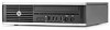
Refer to the following illustration and table to identify the system board connectors.
Figure 2-7
System Board Connections
No.
System Board Connector
System Board Label
Color
Component
1
SATA 3.0
SATA1
light blue
Optical Drive (not present)
2
Power
SATA PWR1
white
Optical Drive (not present)
3
Mobile PCI Express Module
MXM
black
Graphics Card
4
Hood Sensor
HSENSE
white
Hood Sensor
5
USB
MEDIA
black
SD Media Card Reader
6
Mini PCI Express x1
X1PCIEXP1
black
Expansion Card (for example, WLAN
card)
7
Mini-SATA
mSATA
white
Ultra-Small SSD
System Board Connections
13