HP Model 715/100XC hp 9000 series 700 model 715 workstations service handbook - Page 126
Installing Memory Boards
 |
View all HP Model 715/100XC manuals
Add to My Manuals
Save this manual to your list of manuals |
Page 126 highlights
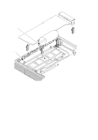
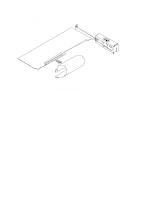
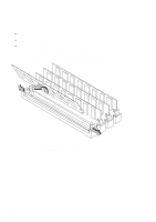
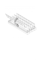
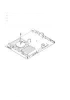
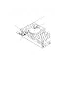
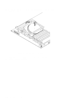
Install the new memory board with its top edge tilted about 45° toward the front of the system unit. Note that the memory board is notched on one end to fit the keyed connector. Press firmly on the memory board to ensure that it is fully seated. Snap the board into place by moving it to a vertical position. Its ends snap into the connector's spring clips. Figure 5-41 shows how to install the memory board. See the memory configuration rules described in Chapter 3 if you are changing the memory configuration. Figure 5-41. Installing Memory Boards Field Replaceable Units 5-41
-
 1
1 -
2
-
3
-
4
-
5
-
6
-
7
-
8
-
9
-
10
-
11
-
12
-
13
-
14
-
15
-
16
-
17
-
18
-
19
-
20
-
21
-
22
-
23
-
24
-
25
-
26
-
27
-
28
-
29
-
30
-
31
-
32
-
33
-
34
-
35
-
36
-
37
-
38
-
39
-
40
-
41
-
42
-
43
-
44
-
45
-
46
-
47
-
48
-
49
-
50
-
51
-
52
-
53
-
54
-
55
-
56
-
57
-
58
-
59
-
60
-
61
-
62
-
63
-
64
-
65
-
66
-
67
-
68
-
69
-
70
-
71
-
72
-
73
-
74
-
75
-
76
-
77
-
78
-
79
-
80
-
81
-
82
-
83
-
84
-
85
-
86
-
87
-
88
-
89
-
90
-
91
-
92
-
93
-
94
-
95
-
96
-
97
-
98
-
99
-
100
-
101
-
102
-
103
-
104
-
105
-
106
-
107
-
108
-
109
-
110
-
111
-
112
-
113
-
114
-
115
-
116
-
117
-
118
-
119
-
120
-
 121
121 -
 122
122 -
 123
123 -
 124
124 -
 125
125 -
 126
126 -
 127
127 -
 128
128 -
 129
129 -
 130
130 -
 131
131 -
132
-
133
-
134
-
135
-
136
-
137
-
138
-
139
-
140
-
141
-
142
-
143
-
144
-
145
-
146
-
147
-
148
-
149
-
150
 |
 |

5–41
Field Replaceable Units
Install the new memory board with its top edge tilted about 45
°
toward the front of
the system unit. Note that the memory board is notched on one end to fit the keyed
connector. Press firmly on the memory board to ensure that it is fully seated. Snap
the board into place by moving it to a vertical position. Its ends snap into the connec-
tor’s spring clips. Figure 5–41 shows how to install the memory board.
See the memory configuration rules described in Chapter 3 if you are changing the
memory configuration.
Figure 5–41.
Installing Memory Boards