HP Nc4000 Maintenance and Service Guide: HP Compaq Notebook nc4000 Series - Page 115
Switch Board, Spare Part Number Information
 |
View all HP Nc4000 manuals
Add to My Manuals
Save this manual to your list of manuals |
Page 115 highlights
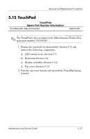
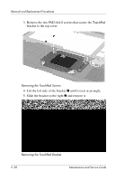
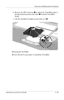
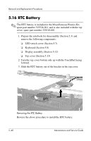
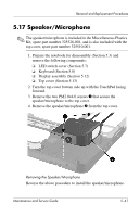
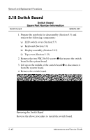
Removal and Replacement Procedures 5.18 Switch Board Switch board Switch Board Spare Part Number Information 325515-001 1. Prepare the notebook for disassembly (Section 5.3) and remove the following components: ❏ LED switch cover (Section 5.7) ❏ Keyboard (Section 5.8) ❏ Display assembly (Section 5.12) ❏ Top cover (Section 5.13) 2. Remove the two PM2.0×3.0 screws 1 that secure the switch board to the system board. 3. Lift up on the middle of the switch board 2 to disconnect it from the system board. 4. Remove the switch board. Removing the Switch Board Reverse the above procedure to install the switch board. 5-42 Maintenance and Service Guide
-
 1
1 -
2
-
3
-
4
-
5
-
6
-
7
-
8
-
9
-
10
-
11
-
12
-
13
-
14
-
15
-
16
-
17
-
18
-
19
-
20
-
21
-
22
-
23
-
24
-
25
-
26
-
27
-
28
-
29
-
30
-
31
-
32
-
33
-
34
-
35
-
36
-
37
-
38
-
39
-
40
-
41
-
42
-
43
-
44
-
45
-
46
-
47
-
48
-
49
-
50
-
51
-
52
-
53
-
54
-
55
-
56
-
57
-
58
-
59
-
60
-
61
-
62
-
63
-
64
-
65
-
66
-
67
-
68
-
69
-
70
-
71
-
72
-
73
-
74
-
75
-
76
-
77
-
78
-
79
-
80
-
81
-
82
-
83
-
84
-
85
-
86
-
87
-
88
-
89
-
90
-
91
-
92
-
93
-
94
-
95
-
96
-
97
-
98
-
99
-
100
-
101
-
102
-
103
-
104
-
105
-
106
-
107
-
108
-
109
-
 110
110 -
 111
111 -
 112
112 -
 113
113 -
 114
114 -
 115
115 -
 116
116 -
 117
117 -
 118
118 -
 119
119 -
 120
120 -
121
-
122
-
123
-
124
-
125
-
126
-
127
-
128
-
129
-
130
-
131
-
132
-
133
-
134
-
135
-
136
-
137
-
138
-
139
-
140
-
141
-
142
-
143
-
144
-
145
-
146
-
147
-
148
-
149
-
150
-
151
-
152
-
153
-
154
-
155
-
156
-
157
-
158
-
159
-
160
-
161
-
162
-
163
-
164
-
165
-
166
-
167
 |
 |
5–42
Maintenance and Service Guide
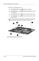
Removal and Replacement Procedures
5.18 Switch Board
1. Prepare the notebook for disassembly (Section 5.3) and
remove the following components:
❏
LED switch cover (Section 5.7)
❏
Keyboard (Section 5.8)
❏
Display assembly (Section 5.12)
❏
Top cover (Section 5.13)
2. Remove the two PM2.0×3.0 screws
1
that secure the switch
board to the system board.
3. Lift up on the middle of the switch board
2
to disconnect it
from the system board.
4. Remove the switch board.
Removing the Switch Board
Reverse the above procedure to install the switch board.
Switch Board
Spare Part Number Information
Switch board
325515-001