HP Nw8000 Maintenance and Service Guide: HP Compaq Notebook nc8000 and nw8000
HP Nw8000 - Compaq Mobile Workstation Manual
 |
UPC - 829160468389
View all HP Nw8000 manuals
Add to My Manuals
Save this manual to your list of manuals |
HP Nw8000 manual content summary:
- HP Nw8000 | Maintenance and Service Guide: HP Compaq Notebook nc8000 and nw8000 - Page 1
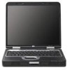
HP Compaq Business Notebook nc8000 Document Part Number: 333954-001 September 2003 This guide is a troubleshooting reference used for maintaining and servicing the notebook. It provides comprehensive information on identifying notebook features, components, and spare parts; troubleshooting notebook - HP Nw8000 | Maintenance and Service Guide: HP Compaq Notebook nc8000 and nw8000 - Page 2
products and services. Nothing herein should be construed as constituting an additional warranty. HP shall not be liable for technical or editorial errors or omissions contained herein. Maintenance and Service Guide HP Compaq Business Notebook nc8000 First Edition September 2003 Document Part Number - HP Nw8000 | Maintenance and Service Guide: HP Compaq Notebook nc8000 and nw8000 - Page 3
from the Security Menu 2-4 Selecting from the Advanced Menu 2-5 2.2 Using Diagnostics for Windows 2-7 Obtaining, Saving or Printing Configuration Information 2-7 Obtaining, Saving or Printing Diagnostic Test Information 2-8 2.3 Troubleshooting Flowcharts 2-10 Maintenance and Service Guide iii - HP Nw8000 | Maintenance and Service Guide: HP Compaq Notebook nc8000 and nw8000 - Page 4
5 Removal and Replacement Procedures 5.1 Serial Number 5-2 5.2 Disassembly Sequence Chart 5-2 5.3 Preparing the Notebook for Disassembly 5-4 5.4 Notebook Feet 5-10 5.5 MultiBay Device 5-11 5.6 Bluetooth Board 5-12 5.7 Optical Drive 5-14 5.8 Keyboard 5-15 iv Maintenance and Service Guide - HP Nw8000 | Maintenance and Service Guide: HP Compaq Notebook nc8000 and nw8000 - Page 5
5-37 5.20 TouchPad 5-38 5.21 Fan Assembly 5-40 5.22 System Board 5-42 6 Specifications A Connector Pin Assignments B Power Cord Set Requirements 3-Conductor Power Cord Set B-1 General Requirements B-1 Country-Specific Requirements B-2 C Screw Listing Index Maintenance and Service Guide v - HP Nw8000 | Maintenance and Service Guide: HP Compaq Notebook nc8000 and nw8000 - Page 6
offers advanced modularity, Mobile Intel Pentium 4 Processor-M processors with 64-bit architecture, ATI MOBILITY RADEON 9600 Pro graphics controllers with 128 or 64 MB of discrete video memory, and extensive multimedia support. HP Compaq Business Notebook nc8000 Maintenance and Service Guide 1-1 - HP Nw8000 | Maintenance and Service Guide: HP Compaq Notebook nc8000 and nw8000 - Page 7
Brand/Series designator C = HP Compaq nc = Business Notebook nc8000 2 Processor type P = Mobile Intel Pentium 4 Processor-M 3 Processor speed 170 = 1.70-GHz 160 = 1.60-GHz 140 = 1.40-GHz 4 Display type and size U = UXGA S = SXGA+ X = XGA 5 = 15.X-inch 5 Hard drive size 80 = 80-GB - HP Nw8000 | Maintenance and Service Guide: HP Compaq Notebook nc8000 and nw8000 - Page 8
XP Professional 2 = Windows 2000 10 SKU# Table 1-2 HP Compaq Business Notebook nc8000 Models The following HP Compaq Business Notebook nc8000 models use configuration code LY2Z and feature the following: ■ Dual point (pointing stick and TouchPad) pointing device ■ 128-MB discrete video memory - HP Nw8000 | Maintenance and Service Guide: HP Compaq Notebook nc8000 and nw8000 - Page 9
The following HP Compaq Business Notebook nc8000 models use configuration code LY2Z and feature the following: ■ Dual point (pointing stick and TouchPad) pointing device ■ 64-MB discrete video memory ■ 8-cell, Li-Ion battery pack ■ TPM security card ■ Smart Card reader ■ 3-year warranty on parts and - HP Nw8000 | Maintenance and Service Guide: HP Compaq Notebook nc8000 and nw8000 - Page 10
HP Compaq Business Notebook nc8000 models use configuration code LY2Z and feature the following: ■ Dual point (pointing stick and TouchPad) pointing device ■ 64-MB discrete video memory ■ 8-cell, Li-Ion battery pack ■ 3-year warranty on parts DN889A ABU DN889A ABA Maintenance and Service Guide 1-5 - HP Nw8000 | Maintenance and Service Guide: HP Compaq Notebook nc8000 and nw8000 - Page 11
Product Description Table 1-2 HP Compaq Business Notebook nc8000 Models (Continued) Cnc8000 P 160 S5 40 D GN 51 2 Asia Pacific Australia Belgium Brazil Czech Republic Denmark ABH DQ616A ABN DQ616A AB9 DQ616A ABE DQ616A AK8 DQ616A UUZ DQ616A ABU DQ616A ABA 1-6 Maintenance and Service Guide - HP Nw8000 | Maintenance and Service Guide: HP Compaq Notebook nc8000 and nw8000 - Page 12
HP Compaq Business Notebook nc8000 models do not use a configuration code and feature the following: ■ Dual point (pointing stick and TouchPad) pointing device ■ 64-MB discrete video memory ■ 8-cell, Li-Ion battery pack ■ 3-year warranty on parts AB8 DJ242A ABU Maintenance and Service Guide 1-7 - HP Nw8000 | Maintenance and Service Guide: HP Compaq Notebook nc8000 and nw8000 - Page 13
Product Description Table 1-2 HP Compaq Business Notebook nc8000 Models (Continued) Cnc8000 P 150 X5 40 D Gp 25 P Belgium Czech Republic Denmark Europe France Germany Greece ABU Cnc8000 P 140 X5 40 D GN 25 P French Canada DH917U ABC United States DH917U ABA 1-8 Maintenance and Service Guide - HP Nw8000 | Maintenance and Service Guide: HP Compaq Notebook nc8000 and nw8000 - Page 14
MB of video memory, varying by notebook model ■ 80-, 60-, or 40-GB high-capacity hard drive, varying by notebook model ■ 256-MB DDR Synchronous DRAM (SDRAM) at 333 MHz, expandable to 2.0-GB ■ Microsoft Windows 2000 or XP Pro, varying by notebook model ■ Full-size Windows 98 keyboard with integrated - HP Nw8000 | Maintenance and Service Guide: HP Compaq Notebook nc8000 and nw8000 - Page 15
65-watt AC adapter with power cord ■ 8-cell Li-Ion battery pack ■ HP PremierSound audio ■ Support for the following optical drives: ❏ 24X Max DVD/CD-RW combination drive ❏ 8X Max DVD+RW drive ❏ 8X Max DVD-ROM drive ❏ 24X Max CD-ROM drive ■ Connectors: ❏ SD Memory Card ❏ Infrared ❏ Two Type II PC - HP Nw8000 | Maintenance and Service Guide: HP Compaq Notebook nc8000 and nw8000 - Page 16
AC power to the notebook. Do not reinsert any battery packs at this time. 6. Turn on the notebook. All passwords and all CMOS settings are cleared. 1.4 Power Management The notebook comes with power management features that extend battery operating time and conserve power. The notebook supports the - HP Nw8000 | Maintenance and Service Guide: HP Compaq Notebook nc8000 and nw8000 - Page 17
Product Description 1.5 External Components The external components on the front panel and right side of the notebook are shown below and described in Table 1-3. Front Panel and Right-Side Components 1-12 Maintenance and Service Guide - HP Nw8000 | Maintenance and Service Guide: HP Compaq Notebook nc8000 and nw8000 - Page 18
PC Cards. ✎ In select notebooks, one PC Card slot may be replaced with a factory-installed Smart Card Reader. Secure Digital (SD) slot Accepts SD Memory Card and MultiMediaCards. MultiBay Supports an optional MultiBay device, such as a drive or battery pack. Infrared port Provides wireless - HP Nw8000 | Maintenance and Service Guide: HP Compaq Notebook nc8000 and nw8000 - Page 19
using a standard USB cable, and connect an optional External MultiBay to the notebook using the External MultiBay-powered USB cable. 2 1394 connector Connects a device that requires high bandwidth, such as a digital camera or other video or audio device. 1-14 Maintenance and Service Guide - HP Nw8000 | Maintenance and Service Guide: HP Compaq Notebook nc8000 and nw8000 - Page 20
is to act as a deterrent. These solutions do not prevent the product from being mishandled or stolen. 11 Optical disk drive Reads and records CD and DVD media. 12 Battery bay Holds the primary battery pack. The battery pack ships outside the notebook. Maintenance and Service Guide 1-15 - HP Nw8000 | Maintenance and Service Guide: HP Compaq Notebook nc8000 and nw8000 - Page 21
Product Description The notebook keyboard components are shown below and described in Table 1-5. Keyboard Components 1-16 Maintenance and Service Guide - HP Nw8000 | Maintenance and Service Guide: HP Compaq Notebook nc8000 and nw8000 - Page 22
Product Description Item 1 2 3 4 5 6 7 8 Table 1-5 Keyboard Components Component Function Microsoft logo key Displays the Windows Start menu. fn key Executes frequently used system functions when pressed in combination with a function key or the esc key. caps lock key Enables capital - HP Nw8000 | Maintenance and Service Guide: HP Compaq Notebook nc8000 and nw8000 - Page 23
Product Description The notebook top components are shown below and described in Table 1-6. Top Components 1-18 Maintenance and Service Guide - HP Nw8000 | Maintenance and Service Guide: HP Compaq Notebook nc8000 and nw8000 - Page 24
block airflow. Power button When the notebook is: ■ Off, press and release to turn on the notebook. ■ In Standby, press and release to exit Standby. ■ In Hibernation, press and release to exit Hibernation. If the system has stopped responding and Windows shutdown procedures cannot be used, press - HP Nw8000 | Maintenance and Service Guide: HP Compaq Notebook nc8000 and nw8000 - Page 25
Product Description Top Components (Continued) 1-20 Maintenance and Service Guide - HP Nw8000 | Maintenance and Service Guide: HP Compaq Notebook nc8000 and nw8000 - Page 26
: Notebook is in Standby. ✎ The power/Standby light also blinks when a battery pack that is the only available power source reaches a critical low-battery condition. The light turns off when the system enters Hibernation or shuts down. Wireless on/off light On: An integrated wireless device has - HP Nw8000 | Maintenance and Service Guide: HP Compaq Notebook nc8000 and nw8000 - Page 27
Product Description The external components on the bottom of the notebook are shown below and described in Table 1-7. Bottom Components 1-22 Maintenance and Service Guide - HP Nw8000 | Maintenance and Service Guide: HP Compaq Notebook nc8000 and nw8000 - Page 28
release latch Releases the primary battery pack from the battery bay. Battery bay Hard drive cover latch Hard drive Holds the primary battery pack. Battery pack ships outside the notebook. Releases the cover on the hard drive bay. Holds the primary hard drive. Maintenance and Service Guide 1-23 - HP Nw8000 | Maintenance and Service Guide: HP Compaq Notebook nc8000 and nw8000 - Page 29
the following device connections: ■ Memory expansion board ■ Mini PCI communications devices ■ Hard drive ■ Display ■ Keyboard, TouchPad, and pointing stick ■ Audio ■ Mobile Intel Pentium 4 Processor-M processors ■ Fan ■ PC Card ■ MCD modem ■ Bluetooth wireless LAN The notebook uses an electrical - HP Nw8000 | Maintenance and Service Guide: HP Compaq Notebook nc8000 and nw8000 - Page 30
The notebook features two system management utilities: ■ Computer Setup-A system information and customization utility that can be used even when your operating system is not working or will not load. This utility includes settings that are not available in Windows. Maintenance and Service Guide - HP Nw8000 | Maintenance and Service Guide: HP Compaq Notebook nc8000 and nw8000 - Page 31
operating system. Use this utility whenever possible to: ❏ Display system information. ❏ Test system components. ❏ Troubleshoot a device configuration problem in Windows XP Professional or Windows XP Home. ✎ It is not necessary to configure a device connected to a USB connector on the notebook or - HP Nw8000 | Maintenance and Service Guide: HP Compaq Notebook nc8000 and nw8000 - Page 32
Troubleshooting Selecting from the File Menu Select Table 2-1 File Menu To Do This System Information Save to Floppy ■ View identification information about the notebook, a port replicator, and any battery packs in the system. ■ View specification information about the processor, memory and - HP Nw8000 | Maintenance and Service Guide: HP Compaq Notebook nc8000 and nw8000 - Page 33
write* ■ CD-ROM or diskette startup System IDs ✎ Settings for a DVD-ROM can be entered in the CD-ROM field. Enter identification numbers for the notebook, a port replicator, and all battery packs in the system. *Not applicable to SuperDisk LS-120 drives. 2-4 Maintenance and Service Guide - HP Nw8000 | Maintenance and Service Guide: HP Compaq Notebook nc8000 and nw8000 - Page 34
legacy support for a USB keyboard. (When USB legacy support is enabled, the keyboard works even when a Windows operating system is not loaded.) ■ Set an optional external monitor or overhead projector connected to a video card in a port replicator as the primary device. (When the notebook display - HP Nw8000 | Maintenance and Service Guide: HP Compaq Notebook nc8000 and nw8000 - Page 35
/disable the reporting of the processor serial number by the processor to the software. HDD Self Test Options Run a quick comprehensive self test on hard drives in the system that support the test features. *Video modes vary even within regions. However, NTSC is common in North America; PAL, in - HP Nw8000 | Maintenance and Service Guide: HP Compaq Notebook nc8000 and nw8000 - Page 36
Troubleshooting 2.2 Using Diagnostics for Windows When you access Diagnostics for Windows, a scan of all system components is displayed on the screen before the diagnostics window opens. You can display more or less information from anywhere within Diagnostics for Windows by selecting Level on the - HP Nw8000 | Maintenance and Service Guide: HP Compaq Notebook nc8000 and nw8000 - Page 37
Troubleshooting Obtaining, Saving or Printing Diagnostic Test Information 1. Access Diagnostics for Windows by selecting Start > Settings > Control Panel > Diagnostics for Windows. 2. Select the Test tab. 3. In the scroll box, select the category or device insert or remove devices. ❏ Unattended Mode - HP Nw8000 | Maintenance and Service Guide: HP Compaq Notebook nc8000 and nw8000 - Page 38
run on the system, the number of times each test has run, the number of errors found on each test, and the total run time of each test. ❏ Error tab-Lists all errors found in the notebook, with the corresponding File > Save As, then print the file from your folder. Maintenance and Service Guide 2-9 - HP Nw8000 | Maintenance and Service Guide: HP Compaq Notebook nc8000 and nw8000 - Page 39
, part 2 No OS loading from hard drive, part 3 No OS loading from diskette drive No OS loading from CD- or DVD-ROM drive No audio, part 1 No audio, part 2 Nonfunctioning device Nonfunctioning keyboard Nonfunctioning pointing device No network or modem connection 2-10 Maintenance and Service Guide - HP Nw8000 | Maintenance and Service Guide: HP Compaq Notebook nc8000 and nw8000 - Page 40
OS loading? Y N Is there sound? Y Check LED board, speaker connections. Go to Flowchart 2.6, No Video. Go to Flowchart 2.9, No OS Loading. Go to Flowchart 2.15, No Audio. N All drives working? Y Go to Flowchart 2.17, Nonfunctioning Device. N Keyboard/ pointing device working? Y Go to Flowchart - HP Nw8000 | Maintenance and Service Guide: HP Compaq Notebook nc8000 and nw8000 - Page 41
up in port replicator? *NOTES: 1. On some models, there is a separate reset button. 2. On some models, the notebook can be reset using the Standby switch and either the lid switch or the main power switch. Go to Flowchart 2.8, Nonfunctioning Port Replicator. 2-12 Maintenance and Service Guide - HP Nw8000 | Maintenance and Service Guide: HP Compaq Notebook nc8000 and nw8000 - Page 42
in battery socket and clean if necessary. Y Power on? N Done Check battery by recharging it, moving it to another notebook, or replacing it. N Power on? Y Replace power supply (if applicable). N Done Power on? Y Go to Flowchart 2.4, No Power, Part 3. Done Maintenance and Service Guide - HP Nw8000 | Maintenance and Service Guide: HP Compaq Notebook nc8000 and nw8000 - Page 43
Troubleshooting Flowchart 2.4-No Power, Part 3 Continued from Flowchart 2.3, No Power, Part 2. Plug directly into AC outlet. Y Power LED on? N Reseat AC adapter in notebook and at power source. Y Power on? N N Power outlet active? Y Replace power cord. Y Power on? N Done Done Try different - HP Nw8000 | Maintenance and Service Guide: HP Compaq Notebook nc8000 and nw8000 - Page 44
Flowchart 2.5-No Power, Part 4 Continued from Flowchart 2.4, No Power, Part 3. Troubleshooting Open notebook. Y Loose or damaged parts? N Reseat loose components and boards and replace damaged items. Close notebook and retest. N Power on? Y Done Replace the following items (if applicable) in - HP Nw8000 | Maintenance and Service Guide: HP Compaq Notebook nc8000 and nw8000 - Page 45
Troubleshooting Flowchart 2.6-No Video, Part 1 No video. Stand-alone or port replicator? Expansion Base Go to Flowchart 2.7, No Video, Part 2. *NOTE: To change from internal to external display, use the hotkey combination. Stand-alone Internal or external display*? External Adjust brightness. - HP Nw8000 | Maintenance and Service Guide: HP Compaq Notebook nc8000 and nw8000 - Page 46
Troubleshooting Flowchart 2.7-No Video, Part 2 Continued from Flowchart 2.6, No Video, Part 1. Remove notebook from port replicator, if connected. Adjust display brightness. Check brightness of external monitor. N Video OK? Y Go to "A" in Flowchart 2.6, No Video, Part 1. Y Video OK? N Check - HP Nw8000 | Maintenance and Service Guide: HP Compaq Notebook nc8000 and nw8000 - Page 47
replicator. Y Port replicator operating? N Done Replace the following port replicator components one at a time. Check notebook operation after each replacement. 1. Power supply 2. I/O board 3. Backplane board 4. Switch box 5. Port replicator motor mechanism 2-18 Maintenance and Service Guide - HP Nw8000 | Maintenance and Service Guide: HP Compaq Notebook nc8000 and nw8000 - Page 48
Troubleshooting Flowchart 2.9-No Operating System (OS) Loading No OS loading.* Reseat power cord in port replicator and power outlet. No OS loading from hard drive, go to Flowchart 2.10, No OS Loading, Hard Drive, Part 1. No OS loading from diskette drive, go to Flowchart 2.13, No OS Loading, - HP Nw8000 | Maintenance and Service Guide: HP Compaq Notebook nc8000 and nw8000 - Page 49
order. N Boot from hard drive? Y Done Done N Boot from diskette? Y Change boot priority through the Setup utility and reboot. N Boot from hard drive? Y Go to Flowchart 2.13, No OS Loading from Diskette Drive. Go to Flowchart 2.17, Nonfunctioning Device. 2-20 Maintenance and Service Guide - HP Nw8000 | Maintenance and Service Guide: HP Compaq Notebook nc8000 and nw8000 - Page 50
format hard drive to bootable C:\ prompt. Hard drive formatted? Y Format hard drive and bring to a bootable Y C:\ prompt. Notebook booted? N Go to Flowchart 2.12, No OS Loading from Hard Drive, Part 3. Load OS using System Restore CD (if applicable). Maintenance and Service Guide 2-21 - HP Nw8000 | Maintenance and Service Guide: HP Compaq Notebook nc8000 and nw8000 - Page 51
Troubleshooting Flowchart 2.12-No OS Loading, Hard Drive, Part 3 Continued from Flowchart 2.11, No OS Loading from Hard Drive, Part 2. N System files on hard drive? Y Install OS and reboot. Y Virus on hard drive? N Run SCANDISK and check for bad sectors. N Can bad sectors be fixed? Y Clean - HP Nw8000 | Maintenance and Service Guide: HP Compaq Notebook nc8000 and nw8000 - Page 52
notebook. Check diskette for system files. Try different diskette. Y Nonsystem disk error? N 1. Replace diskette drive. 2. Replace system board. Y OS loading? N Done Change boot priority using the Setup utility. Go to Flowchart 2.17, Nonfunctioning Device. Maintenance and Service Guide - HP Nw8000 | Maintenance and Service Guide: HP Compaq Notebook nc8000 and nw8000 - Page 53
device? Y Done Go to Flowchart 2.17, Nonfunctioning Device. Y Clear CMOS. Booting order correct? N Refer to Section 1.3, "Clearing a Password," for instructions. Correct boot order using the Setup utility. Go to Flowchart 2.17, Nonfunctioning Device. 2-24 Maintenance and Service Guide - HP Nw8000 | Maintenance and Service Guide: HP Compaq Notebook nc8000 and nw8000 - Page 54
Troubleshooting Flowchart 2.15-No Audio, Part 1 Y No audio. Turn up audio internally or externally. Audio? Done N Y Notebook in port replicator (if applicable)? N Go to Flowchart 2.16, No Audio, Part 2. Undock N Internal audio? Y Go to Flowchart 2.16, No Audio, Part 2. Replace the - HP Nw8000 | Maintenance and Service Guide: HP Compaq Notebook nc8000 and nw8000 - Page 55
drivers and set configuration in OS. Connect to external speaker. N Audio? Y Replace audio board and speaker connections in notebook (if applicable). Y Audio? N Done 1. Replace internal speakers. 2. Replace audio board (if applicable). 3. Replace system board. 2-26 Maintenance and Service - HP Nw8000 | Maintenance and Service Guide: HP Compaq Notebook nc8000 and nw8000 - Page 56
plugs for bent or broken pins or other damage. Clear CMOS. Reattach device. Close notebook, plug in power, and reboot. N Device boots properly? Y Y Any physical device detected? N Replace hard drive. Replace NIC. If integrated NIC, replace system board. Fix or replace broken item. Go to Flowchart - HP Nw8000 | Maintenance and Service Guide: HP Compaq Notebook nc8000 and nw8000 - Page 57
operating properly. Connect notebook to good external keyboard. N External device works? Y Replace system board. Reseat internal keyboard connector (if applicable). N OK? Y Replace internal keyboard or cable. Y Done OK? N Replace system board. Done 2-28 Maintenance and Service Guide - HP Nw8000 | Maintenance and Service Guide: HP Compaq Notebook nc8000 and nw8000 - Page 58
Connect notebook to good external pointing device. N External device works? Y Replace system board. Reseat internal pointing device connector (if applicable). N OK? Y Replace internal pointing device or cable. Y Done OK? N Replace system board. Done Maintenance and Service Guide 2-29 - HP Nw8000 | Maintenance and Service Guide: HP Compaq Notebook nc8000 and nw8000 - Page 59
nondigital line. N N Y NIC/modem configured in OS? Y Reload drivers and OK? reconfigure. N Done Disconnect all power from the notebook and open. Reseat NIC/modem (if applicable). Replace NIC/modem (if applicable). Y OK? N Done Replace system board. 2-30 Maintenance and Service Guide - HP Nw8000 | Maintenance and Service Guide: HP Compaq Notebook nc8000 and nw8000 - Page 60
parts breakdown and a reference for spare part numbers and option part numbers. 3.1 Serial Number Location When ordering parts or requesting information, provide the notebook serial number and model number located on the bottom of the notebook. Serial Number Location Maintenance and Service Guide - HP Nw8000 | Maintenance and Service Guide: HP Compaq Notebook nc8000 and nw8000 - Page 61
Illustrated Parts Catalog 3.2 Notebook Major Components Notebook Major Components 3-2 Maintenance and Service Guide - HP Nw8000 | Maintenance and Service Guide: HP Compaq Notebook nc8000 and nw8000 - Page 62
display hinges RTC battery Mini PCI communications board shield Bluetooth cover Battery bezel Hard drive cover Not illustrated: Notebook feet (4) LED switch cover 345063-001 Keyboards (include pointing stick Top cover (includes TouchPad and speaker) 345061-001 Maintenance and Service Guide 3-3 - HP Nw8000 | Maintenance and Service Guide: HP Compaq Notebook nc8000 and nw8000 - Page 63
Illustrated Parts Catalog Notebook Major Components (Continued) 3-4 Maintenance and Service Guide - HP Nw8000 | Maintenance and Service Guide: HP Compaq Notebook nc8000 and nw8000 - Page 64
-001 12 System boards (include thermal grease) With 128-MB of video memory With 64-MB of video memory 349206-001 345064-001 13 Security card 345856-001 14 Mini PCI communications boards 802.11a/b/g LAN NIC 802.11b/g LAN NIC 802.11b W500 modem board (for use in Japan) 802.11b wireless LAN - HP Nw8000 | Maintenance and Service Guide: HP Compaq Notebook nc8000 and nw8000 - Page 65
Illustrated Parts Catalog Notebook Major Components (Continued) 3-6 Maintenance and Service Guide - HP Nw8000 | Maintenance and Service Guide: HP Compaq Notebook nc8000 and nw8000 - Page 66
18 Bluetooth board (includes Bluetooth cable, item 6b) 348277-001 19 Hard drives (all 5400-rpm, and include hard drive bezel and frame) 80-GB 60-GB 60-GB 40-GB 345632-001 345855-001 345631-001 345630-001 20 Battery pack, 8-cell, 4.4 Wh, Li-Ion 338669-001 Maintenance and Service Guide 3-7 - HP Nw8000 | Maintenance and Service Guide: HP Compaq Notebook nc8000 and nw8000 - Page 67
3-2 Miscellaneous Plastics Kit Components Spare Part Number 345066-001 Item Description 1 Left and right display hinges 2 RTC battery 3 Mini PCI communications board shield 4 Bluetooth cover 5 Battery bezel 6 Hard drive cover 7 Notebook feet (4) 3-8 Maintenance and Service Guide - HP Nw8000 | Maintenance and Service Guide: HP Compaq Notebook nc8000 and nw8000 - Page 68
Illustrated Parts Catalog 3.4 Miscellaneous Cable Kit Components Miscellaneous Cable Kit Components Table 3-3 Miscellaneous Cable Kit Components Spare Part Number 340056-001 Item Description 1 Bluetooth cable 2 Modem cable Maintenance and Service Guide 3-9 - HP Nw8000 | Maintenance and Service Guide: HP Compaq Notebook nc8000 and nw8000 - Page 69
Mass Storage Devices Table 3-5 Mass Storage Devices Spare Part Number Information Item Description Spare Part Number 1 Hard drives (all 5400-rpm, and include hard drive bezel and frame) 80-GB 60-GB 60-GB 40-GB 345632-001 345855-001 345631-001 345630-001 3-10 Maintenance and Service Guide - HP Nw8000 | Maintenance and Service Guide: HP Compaq Notebook nc8000 and nw8000 - Page 70
DVD-ROM/CD-RW combination drive 24X Max CD-ROM drive 349242-001 349241-001 349243-001 349240-001 MultiBay devices 1.44-MB diskette drive 24X Max CD-ROM drive 8X Max Slim DVD/R+W drive 4X Max Regular DVD/R+W drive 241995-001 228746-001 251292-001 344256-001 Maintenance and Service Guide 3-11 - HP Nw8000 | Maintenance and Service Guide: HP Compaq Notebook nc8000 and nw8000 - Page 71
Spare Parts: Miscellaneous (not illustrated) Description Spare Part Number Common Port Replicator 339096-001 339097-001 Power cords Australia Brazil Denmark Europe/Middle East C, "Screw Listing," for more information on screw specifications and usage.) 345057-001 ■ Torx T8M2.0×6.0 screw - HP Nw8000 | Maintenance and Service Guide: HP Compaq Notebook nc8000 and nw8000 - Page 72
procedures: ■ Magnetic screwdriver ■ Phillips P0 screwdriver ■ Torx T5 screwdriver ■ Torx T8 screwdriver ■ 4.0-mm socket for hard drive alignment pins ■ Flat-bladed screwdriver ■ Tool kit (includes connector removal tool, loopback plugs, and case utility tool) Maintenance and Service Guide 4-1 - HP Nw8000 | Maintenance and Service Guide: HP Compaq Notebook nc8000 and nw8000 - Page 73
from the work area to prevent damage. Plastic Parts Using excessive force during disassembly and reassembly can damage plastic parts. Use care when handling the plastic parts. Apply pressure only at the points designated in the maintenance instructions. Cables and Connectors Cables must be handled - HP Nw8000 | Maintenance and Service Guide: HP Compaq Notebook nc8000 and nw8000 - Page 74
the following precautions: ■ Before removing or inserting a hard drive, shut down the notebook. If you are unsure whether the notebook is off or in Hibernation, turn the notebook on, then shut it down. ■ Before removing a diskette drive or optical drive, ensure that a diskette or disc is not in - HP Nw8000 | Maintenance and Service Guide: HP Compaq Notebook nc8000 and nw8000 - Page 75
power to alter device parts in their containers until the parts arrive at static-free workstations. ■ Place items on a grounded surface before removing items from their containers. ■ Always be properly grounded when touching a sensitive component or assembly. 4-4 Maintenance and Service Guide - HP Nw8000 | Maintenance and Service Guide: HP Compaq Notebook nc8000 and nw8000 - Page 76
components, parts, and assemblies by the case or PCM laminate. Handle these items only at static-free workstations. ■ Avoid contact with pins, leads, or circuitry. ■ Turn off power and input signals before inserting or removing connectors or test equipment. Maintenance and Service Guide 4-5 - HP Nw8000 | Maintenance and Service Guide: HP Compaq Notebook nc8000 and nw8000 - Page 77
tabletop workstations with ground cords of one megohm resistance ■ Static-dissipative tables or floor mats with hard ties to the ground ■ Field service kits ■ Static awareness labels ■ Material-handling packages ■ Nonconductive plastic bags, tubes, or boxes 4-6 Maintenance and Service Guide - HP Nw8000 | Maintenance and Service Guide: HP Compaq Notebook nc8000 and nw8000 - Page 78
little as 700 V. Table 4-2 lists the shielding protection provided by antistatic bags and floor mats. Table 4-2 Static-Shielding Materials Material Use Voltage Protection Level Antistatic plastic Bags 1,500 V Carbon-loaded plastic Floor mats 7,500 V Metallized laminate Floor mats 5,000 - HP Nw8000 | Maintenance and Service Guide: HP Compaq Notebook nc8000 and nw8000 - Page 79
provides removal and replacement procedures. There are 62 screws in eight different sizes that must be removed, replaced, and loosened when servicing the notebook. Make note of each screw size and location during removal and replacement. Refer to Appendix C, "Screw Listing," for detailed information - HP Nw8000 | Maintenance and Service Guide: HP Compaq Notebook nc8000 and nw8000 - Page 80
number to be referenced when removing notebook components. Disassembly Sequence Chart Section Description # of Screws Removed 5.3 Preparing the notebook for disassembly Battery pack Hard drive 0 1 to remove 4 screws and 2 alignment pins to disassemble 5-2 Maintenance and Service Guide - HP Nw8000 | Maintenance and Service Guide: HP Compaq Notebook nc8000 and nw8000 - Page 81
MultiBay device 0 5.6 Bluetooth board 3 5.7 Optical drive 1 5.8 Keyboard 1 5.9 Memory expansion board 0 5.10 Modem board 2 5.11 Mini PCI communications board 2 5.12 Heat sink 5 5.13 Processor 0 5.14 LED switch cover 1 5.15 RTC battery 0 5.16 Security card 1 5.17 - HP Nw8000 | Maintenance and Service Guide: HP Compaq Notebook nc8000 and nw8000 - Page 82
devices connected to the notebook. 3. Disconnect the power cord. 4. Remove the battery pack by following these steps: Spare Part Number Information Battery pack, 8-cell, 4.4 Wh, Li-Ion 338669-001 a. Turn the notebook upside down with the front panel facing you. 5-4 Maintenance and Service - HP Nw8000 | Maintenance and Service Guide: HP Compaq Notebook nc8000 and nw8000 - Page 83
Removal and Replacement Procedures b. Slide and hold the battery release latch 1 toward the back of the notebook. c. Use the notch in the battery pack to slide the battery pack to the right 2. d. Remove the battery pack. Removing the Battery Pack Maintenance and Service Guide 5-5 - HP Nw8000 | Maintenance and Service Guide: HP Compaq Notebook nc8000 and nw8000 - Page 84
the battery bezel by sliding it down and off of the battery pack. ✎ The battery bezel is included in the Miscellaneous Plastics Kit, spare part number 345066-001. Removing the Battery Bezel Reverse the above procedure to install the battery pack and battery bezel. 5-6 Maintenance and Service Guide - HP Nw8000 | Maintenance and Service Guide: HP Compaq Notebook nc8000 and nw8000 - Page 85
Slide and hold the tab on the hard drive cover to the left 2. d. Swing the right edge of the hard drive cover up and to the left 3. ✎ The hard drive cover is included in the Miscellaneous Plastics Kit, spare part number 345066-001. Removing the Hard Drive Cover Maintenance and Service Guide 5-7 - HP Nw8000 | Maintenance and Service Guide: HP Compaq Notebook nc8000 and nw8000 - Page 86
Removal and Replacement Procedures e. Use the Mylar tab 1 to slide the hard drive to the right 2 to disconnect it from the system board. f. Lift the hard drive straight up to remove it 3. Removing the Hard Drive 5-8 Maintenance and Service Guide - HP Nw8000 | Maintenance and Service Guide: HP Compaq Notebook nc8000 and nw8000 - Page 87
3 that secure the hard drive to the hard drive frame. i. Remove the hard drive from the hard drive frame 4. j. Remove the hard drive connector from the hard drive 5. Disassembling the Hard Drive Reverse the above procedure to assemble and install the hard drive. Maintenance and Service Guide 5-9 - HP Nw8000 | Maintenance and Service Guide: HP Compaq Notebook nc8000 and nw8000 - Page 88
Replacement Procedures 5.4 Notebook Feet The notebook feet are adhesive-backed rubber pads. The feet are included in the Miscellaneous Plastics Kit, spare part number 345066-001. The feet attach to the base enclosure as illustrated below. Notebook Feet Locations 5-10 Maintenance and Service Guide - HP Nw8000 | Maintenance and Service Guide: HP Compaq Notebook nc8000 and nw8000 - Page 89
Removal and Replacement Procedures 5.5 MultiBay Device Spare Part Number Information 1.44-MB diskette drive 24X Max CD-ROM drive 8X Max DVD-R+W drive 4X Max DVD-R+W drive 241995-001 228746-001 251292-001 344256-001 1. Prepare the notebook for disassembly (refer to Section 5.3). 2. Turn the - HP Nw8000 | Maintenance and Service Guide: HP Compaq Notebook nc8000 and nw8000 - Page 90
you. 3. Remove the T8M2.0×6.0 screw 1 that secures the Bluetooth cover to the notebook. 4. Lift the cover straight up to remove it 2. ✎ The Bluetooth cover is included in the Miscellaneous Plastics Kit, spare part number 345066-001. Removing the Bluetooth Cover 5-12 Maintenance and Service Guide - HP Nw8000 | Maintenance and Service Guide: HP Compaq Notebook nc8000 and nw8000 - Page 91
Cables Kit, spare part number 345056-001. 6. Remove the two PM1.5×3.0 screws 3 that secure the Bluetooth board to the Bluetooth cover. 7. Remove the board from the cover 4. Removing the Bluetooth Board Reverse the above procedure to install the Bluetooth board. Maintenance and Service Guide 5-13 - HP Nw8000 | Maintenance and Service Guide: HP Compaq Notebook nc8000 and nw8000 - Page 92
the notebook. 4. Insert a paper clip or similar tool into the optical drive release hole to open the optical drive tray 2. 5. Use the optical drive tray to remove the optical drive 3. Removing the Optical Drive Reverse the above procedure to install the optical drive. 5-14 Maintenance and Service - HP Nw8000 | Maintenance and Service Guide: HP Compaq Notebook nc8000 and nw8000 - Page 93
Removal and Replacement Procedures 5.8 Keyboard Spare Part Number Information Keyboards (include pointing stick) Brazil 341520-001 1. Prepare the notebook for disassembly (refer to Section 5.3). 2. Turn the notebook upside down with the front panel facing you. Maintenance and Service Guide 5-15 - HP Nw8000 | Maintenance and Service Guide: HP Compaq Notebook nc8000 and nw8000 - Page 94
Removal and Replacement Procedures 3. Remove the T8M2.×6.0 screw that secures the keyboard to the notebook. Removing the Keyboard Screw 5-16 Maintenance and Service Guide - HP Nw8000 | Maintenance and Service Guide: HP Compaq Notebook nc8000 and nw8000 - Page 95
the notebook right-side up with the front facing you. 5. Open the notebook. 6. Slide the four tabs on the top edge of the keyboard toward you 1. 7. Lift the rear edge of the keyboard up and swing it toward you 2 until it rests on the palm rest. Releasing the Keyboard Maintenance and Service Guide - HP Nw8000 | Maintenance and Service Guide: HP Compaq Notebook nc8000 and nw8000 - Page 96
stick cable is attached and disconnect the cable 2. 9. Release the ZIF connector 3 to which the keyboard cable is attached and disconnect the cable 4. Disconnecting the Keyboard Cables 10. Remove the keyboard. Reverse the above procedure to install the keyboard. 5-18 Maintenance and Service Guide - HP Nw8000 | Maintenance and Service Guide: HP Compaq Notebook nc8000 and nw8000 - Page 97
Removal and Replacement Procedures 5.9 Memory Expansion Board Spare Part Number Information 1024-MB (1.0-GB), 333 MHz 512-MB, 333 MHz 256-MB, 333 MHz 336579-001 336578-001 336577-001 1. Prepare the notebook for disassembly (Section 5.3). 2. Release the keyboard (Section 5.8). 3. Spread the - HP Nw8000 | Maintenance and Service Guide: HP Compaq Notebook nc8000 and nw8000 - Page 98
5.3). 2. Release the keyboard (Section 5.8). 3. Remove the two T8M2.0×4.0 screws 1 that secure the modem board to the notebook. 4. Lift up on the right side of the modem board 2 to disconnect the board from the system board. Removing the Modem Board Screws 5-20 Maintenance and Service Guide - HP Nw8000 | Maintenance and Service Guide: HP Compaq Notebook nc8000 and nw8000 - Page 99
Removal and Replacement Procedures 5. Turn the modem board upside down 1. 6. Disconnect the modem cable 2 from the modem. Disconnecting the Modem Board Cable 7. Remove the modem board. Reverse the above procedure to install the modem board. Maintenance and Service Guide 5-21 - HP Nw8000 | Maintenance and Service Guide: HP Compaq Notebook nc8000 and nw8000 - Page 100
Part Number Information 802.11a/b/g LAN NIC 802.11b/g LAN NIC 802.11b W500 modem board (for use in Japan) 802.11b wireless LAN (MOW) 802.11b wireless LAN (ROW) 325525-001 325526-001 339742-291 345641-001 345640-001 1. Prepare the notebook for disassembly (Section 5.3). 2. Release the keyboard - HP Nw8000 | Maintenance and Service Guide: HP Compaq Notebook nc8000 and nw8000 - Page 101
3. Removing the Mini PCI Communications Board 8. Remove the Mini PCI communications board. Reverse the above procedure to install the Mini PCI communications board. Maintenance and Service Guide 5-23 - HP Nw8000 | Maintenance and Service Guide: HP Compaq Notebook nc8000 and nw8000 - Page 102
Procedures 5.12 Heat Sink Spare Part Number Information Heat sink (includes grease) 345067-001 1. Prepare the notebook for disassembly (Section 5.3). 2. Release the keyboard (Section 5.8). 3. Remove the five T8M2.0×4.0 screws 1 that secure the heat sink to the notebook. 4. Lift the front edge of - HP Nw8000 | Maintenance and Service Guide: HP Compaq Notebook nc8000 and nw8000 - Page 103
grease to both surfaces. Removing the Thermal Grease From the Heat Sink and Processor Reverse the above procedure to install the heat sink. Maintenance and Service Guide 5-25 - HP Nw8000 | Maintenance and Service Guide: HP Compaq Notebook nc8000 and nw8000 - Page 104
4 Processor-M 1.7-GHz Mobile Intel Pentium 4 Processor-M 1.6-GHz Mobile Intel Pentium 4 Processor-M 1.4-GHz 340165-001 319777-001 319775-001 1. Prepare the notebook for disassembly (Section 5.3). 2. Release the keyboard (Section 5.8). 3. Remove the heat sink (Section 5.12). 4. Use a flat bladed - HP Nw8000 | Maintenance and Service Guide: HP Compaq Notebook nc8000 and nw8000 - Page 105
cover 345063-001 1. Prepare the notebook for disassembly (Section 5.3). 2. Turn the notebook upside down with the rear panel facing you. 3. Remove the T8M2.0×6.0 screw that secures the LED switch cover to the notebook. Removing the LED Switch Cover Screw Maintenance and Service Guide 5-27 - HP Nw8000 | Maintenance and Service Guide: HP Compaq Notebook nc8000 and nw8000 - Page 106
facing you. 5. Open the notebook. 6. Lift the left 1 and right 2 sides of the LED switch cover to disengage the cover from the notebook. 7. Remove the LED switch cover. Removing the LED Switch Cover Reverse the above procedure to install the LED switch cover. 5-28 Maintenance and Service Guide - HP Nw8000 | Maintenance and Service Guide: HP Compaq Notebook nc8000 and nw8000 - Page 107
is included in the Miscellaneous Plastics Kit, spare part number 345066-001. 1. Prepare the notebook for disassembly (Section 5.3). 2. Remove the LED switch cover (Section 5.14). 3. Disconnect the RTC battery cable 1 from the system board. 4. Slide the RTC battery out of the clips in the top cover - HP Nw8000 | Maintenance and Service Guide: HP Compaq Notebook nc8000 and nw8000 - Page 108
16 Security Card Security card Spare Part Number Information 345856-001 1. Prepare the notebook for disassembly (Section 5.3). 2. Remove the LED switch cover (Section 5.14). 3. Remove the PM1.5×3.0 screw 1 that secures the security card to the system board. 4. Lift the security card straight up - HP Nw8000 | Maintenance and Service Guide: HP Compaq Notebook nc8000 and nw8000 - Page 109
5.17 Display Assembly Spare Part Number Information 15.0-inch, UXGA, TFT 15.0-inch, SXGA+, TFT 15.0-inch, XGA, TFT 345060-001 345059-001 345058-001 1. Prepare the notebook for disassembly (Section 5.3). 2. Remove the keyboard (Section 5.8). 3. Disconnect the wireless antenna cables from the Mini - HP Nw8000 | Maintenance and Service Guide: HP Compaq Notebook nc8000 and nw8000 - Page 110
the notebook with the rear panel facing toward you. 8. Remove the two T8M2.0×6.0 screws 1 that secure the display hinge covers to the notebook. 9. Remove the two T8M2.0×6.0 screws 2 that secure the display assembly to the notebook. Removing the Display Screws 5-32 Maintenance and Service Guide - HP Nw8000 | Maintenance and Service Guide: HP Compaq Notebook nc8000 and nw8000 - Page 111
, remove the display hinge covers 2 from the display assembly. ✎ The display hinge covers are included in the Miscellaneous Plastics Kit, spare part number 345066-001. Removing the Display Assembly Reverse the above procedure to install the display assembly. Maintenance and Service Guide 5-33 - HP Nw8000 | Maintenance and Service Guide: HP Compaq Notebook nc8000 and nw8000 - Page 112
Removal and Replacement Procedures 5.18 Top Cover Spare Part Number Information Top cover (includes TouchPad and speaker) 345061-001 1. Prepare the notebook for disassembly (Section 5.3). 2. Remove the keyboard (Section 5.8). 3. Remove the LED switch cover (Section 5.14). 4. Remove the display - HP Nw8000 | Maintenance and Service Guide: HP Compaq Notebook nc8000 and nw8000 - Page 113
up with the front panel facing you. 8. Remove the TM2.0×4.0 screw 1 near the fan that secures the top cover to the notebook. 9. Lift the front edge of the top cover 2 until the speaker 3, TouchPad 4, and microphone 5 cables are accessible. Releasing the Top Cover Maintenance and Service Guide 5-35 - HP Nw8000 | Maintenance and Service Guide: HP Compaq Notebook nc8000 and nw8000 - Page 114
1 and microphone cables 2. 11. Release the ZIF connector 3 to which the TouchPad cable is attached and disconnect the TouchPad cable 4 from the system board. Disconnecting the Top Cover Cables 12. Remove the top cover. Reverse the above procedure to install the top cover. 5-36 Maintenance and - HP Nw8000 | Maintenance and Service Guide: HP Compaq Notebook nc8000 and nw8000 - Page 115
is included with the top cover, spare part number 345061-001. 1. Prepare the notebook for disassembly (Section 5.3) and remove the following components: ❏ Keyboard (Section 5.8) ❏ LED switch cover (Section Reverse the above procedure to install the speaker. Maintenance and Service Guide 5-37 - HP Nw8000 | Maintenance and Service Guide: HP Compaq Notebook nc8000 and nw8000 - Page 116
are included with the top cover, spare part number 345061-001. 1. Prepare the notebook for disassembly (Section 5.3) and remove the following components: ❏ Keyboard (Section 5.8) ❏ LED switch cover (Section Removing the TouchPad Bracket 4. Remove the bracket. 5-38 Maintenance and Service Guide - HP Nw8000 | Maintenance and Service Guide: HP Compaq Notebook nc8000 and nw8000 - Page 117
which the TouchPad cable is attached and disconnect the cable 3. Removing the TouchPad Reverse the above procedure to install the TouchPad and bracket. Maintenance and Service Guide 5-39 - HP Nw8000 | Maintenance and Service Guide: HP Compaq Notebook nc8000 and nw8000 - Page 118
Fan assembly 345065-001 1. Prepare the notebook for disassembly (Section 5.3) and remove the following components: ❏ Keyboard (Section 5.8) ❏ Heat sink (Section 5.12) ❏ LED switch cover (Section 5.14) ❏ Display assembly (Section 5.17) ❏ Top cover (Section 5.18) 5-40 Maintenance and Service Guide - HP Nw8000 | Maintenance and Service Guide: HP Compaq Notebook nc8000 and nw8000 - Page 119
and Replacement Procedures 2. Disconnect the fan cable 1. 3. Remove the T8M2.0×4.0 screw 2 that secures the fan assembly to the notebook. 4. Remove the fan assembly 3 from the notebook. 5. Remove the three PM1.5×4.0 screws 4 that secure the fan to the fan housing. 6. Remove the fan 5. Removing the - HP Nw8000 | Maintenance and Service Guide: HP Compaq Notebook nc8000 and nw8000 - Page 120
the replacement system board: ■ Memory expansion boards (Section 5.9) ■ Modem board (Section 5.10) ■ Mini PCI communications board (Section 5.11) ■ Heat sink (Section 5.12) ■ Processor (Section 5.13) ■ Real time clock battery (Section 5.15) ■ Security card (Section 5.16) 1. Prepare the notebook for - HP Nw8000 | Maintenance and Service Guide: HP Compaq Notebook nc8000 and nw8000 - Page 121
Removal and Replacement Procedures 2. Remove the four T8M2.0×4.0 screws that secure the system board to the notebook. Removing the System Board Screws Maintenance and Service Guide 5-43 - HP Nw8000 | Maintenance and Service Guide: HP Compaq Notebook nc8000 and nw8000 - Page 122
the base enclosure out 1 to allow the system board to clear the base enclosure. 4. Lift the front edge of the system board 2 until the board clears the base enclosure. 5. Slide the system board forward 3 to remove it from the notebook. Removing the System Board 5-44 Maintenance and Service Guide - HP Nw8000 | Maintenance and Service Guide: HP Compaq Notebook nc8000 and nw8000 - Page 123
, disconnect the modem cable from the system board and remove the cable. ✎ The modem cable is included in the Miscellaneous Cables Kit, spare part number 345056-001. Removing the Modem Cable Reverse the above procedure to install the modem cable and system board. Maintenance and Service Guide 5-45 - HP Nw8000 | Maintenance and Service Guide: HP Compaq Notebook nc8000 and nw8000 - Page 124
chapter provides physical and performance specifications. Dimensions Table 6-1 Notebook Height Width Depth 4.1 cm 32.6 cm 27.5 cm 1.61 in 12.84 in 10.83 in Weight (with main battery pack and MultiBay weight saver) 2.95 kg 6.50 lb Stand-alone power requirements Nominal operating voltage (Li - HP Nw8000 | Maintenance and Service Guide: HP Compaq Notebook nc8000 and nw8000 - Page 125
Specifications Table 6-1 Notebook (Continued) Altitude (unpressurized) Operating (14.7 to 10.1 psia) Nonoperating (14.7 to 4.4 psia product safety standards specify thermal limits for plastic surfaces. The notebook operates well within this range of temperatures. 6-2 Maintenance and Service Guide - HP Nw8000 | Maintenance and Service Guide: HP Compaq Notebook nc8000 and nw8000 - Page 126
Specifications Dimensions Table 6-2 15.0-inch, UXGA, TFT Display Height Width Diagonal 30.4 cm RGB vertical stripe Backlight Edge lit Character display 80 × 25 Total power consumption 6.5 W Viewing angle +/- 85° horizontal, +15/-35° vertical typical Maintenance and Service Guide 6-3 - HP Nw8000 | Maintenance and Service Guide: HP Compaq Notebook nc8000 and nw8000 - Page 127
Specifications Dimensions Table 6-3 15.1-inch, SXGA+, TFT Display Height Width Diagonal 304. cm RGB vertical stripe Backlight Edge lit Character display 80 × 25 Total power consumption 5.75 W Viewing angle +/- 35° horizontal, +15/-35° vertical typical 6-4 Maintenance and Service Guide - HP Nw8000 | Maintenance and Service Guide: HP Compaq Notebook nc8000 and nw8000 - Page 128
Specifications Dimensions Table 6-4 15.0-inch, XGA, TFT Display Height Width Diagonal 30.4 cm RGB vertical stripe Backlight Edge lit Character display 80 × 25 Total power consumption 5.75 W Viewing angle +/- 35° horizontal, +15/-35° vertical typical Maintenance and Service Guide 6-5 - HP Nw8000 | Maintenance and Service Guide: HP Compaq Notebook nc8000 and nw8000 - Page 129
5°C to 55°C (41°F to 131°F) 5°C to 55°C (41°F to 131°F) 5°C to 55°C (41°F to 131°F) 11 GB = 1,073,741,824 bytes. 2Actual drive specifications may differ slightly. Certain restrictions and exclusions apply. Consult the HP Customer Support Center for details. 6-6 Maintenance and Service Guide - HP Nw8000 | Maintenance and Service Guide: HP Compaq Notebook nc8000 and nw8000 - Page 130
-hour capacity Watt-hour capacity 11.1 V 3.96 Ah 40 Wh Temperature Operating Nonoperating 5°C to 45°C -20°C to 60°C 41°F to 113°F -4°F to 140°F Recharge time System in Standby mode System on (depending on system power consumption) 2 to 3 hours 2 to 5 hours Maintenance and Service Guide 6-7 - HP Nw8000 | Maintenance and Service Guide: HP Compaq Notebook nc8000 and nw8000 - Page 131
Specifications Applicable disc Table 6-8 24X DVD/CD-RW Drive DVD-5, DVD-9, DVD-10 CD-ROM (Mode 1 and 2) CD Digital Audio CD-XA ready (Mode 2, Form 1 and 2) CD-I ready (Mode 2, Form 1 and 2) CD-R rate) 16.6 MB/s Startup time < 15 seconds Stop time < 6 seconds 6-8 Maintenance and Service Guide - HP Nw8000 | Maintenance and Service Guide: HP Compaq Notebook nc8000 and nw8000 - Page 132
Specifications Applicable disc Table 6-9 24X CD-RW Drive DVD-5, DVD-9, DVD-10 CD-ROM (Mode 1 and 2) CD Digital Audio CD-XA ready (Mode 2, Form 1 and 2) CD-I ready (Mode 2, Form 1 and 2) CD-R ( rate) 16.6 MB/s Startup time < 15 seconds Stop time < 6 seconds Maintenance and Service Guide 6-9 - HP Nw8000 | Maintenance and Service Guide: HP Compaq Notebook nc8000 and nw8000 - Page 133
Specifications Applicable disc Table 6-10 8X DVD-ROM Drive DVD-5, DVD-9, DVD-10 CD-ROM (Mode 1 and 2) CD Digital Audio CD-XA ready (Mode 2, Form 1 and stroke CD media < 150 ms < 225 ms < 110 ms < 200 ms Audio output level Line-out, 0.7 Vrms Cache buffer 512 KB/s Data transfer rate Max 24X - HP Nw8000 | Maintenance and Service Guide: HP Compaq Notebook nc8000 and nw8000 - Page 134
Specifications Applicable disc Table 6-11 24X CD-ROM Drive DVD-5, DVD-9, DVD-10 CD-ROM (Mode 1 and 2) CD Digital Audio CD-XA ready (Mode 2, Track pitch 1.6 µm Access time Random Full stroke < 150 ms < 300 ms Audio output level Line-out, 0.7 Vrms Cache buffer 128 KB/s Data transfer rate - HP Nw8000 | Maintenance and Service Guide: HP Compaq Notebook nc8000 and nw8000 - Page 135
, DMA3, none) DMA2* Diskette drive DMA3 ECP parallel port LPT1 (default; alternate = DMA0, none) DMA4 DMA controller cascading (not available) DMA5* Available for PC Card DMA6 Not assigned DMA7 Not assigned *PC Card controller can use DMA 1, 2, or 5. 6-12 Maintenance and Service Guide - HP Nw8000 | Maintenance and Service Guide: HP Compaq Notebook nc8000 and nw8000 - Page 136
Specifications Hardware IRQ System Function Table 6-13 System Interrupts IRQ0 System timer IRQ1 Keyboard controller IRQ2 Cascaded IRQ3 COM2 IRQ4 COM1 IRQ5 Audio (default)* IRQ6 Diskette drive IRQ7 Parallel port IRQ8 Real time clock (RTC) IRQ9 Assigned by operating system - HP Nw8000 | Maintenance and Service Guide: HP Compaq Notebook nc8000 and nw8000 - Page 137
chipset configuration registers Unused 87334 "Super I/O" configuration for CPU Counter/timer registers Unused Keyboard controller Port B Unused Keyboard controller Unused NMI enable/RTC Unused DMA page registers Unused Port A Unused Interrupt controller no. 2 6-14 Maintenance and Service Guide - HP Nw8000 | Maintenance and Service Guide: HP Compaq Notebook nc8000 and nw8000 - Page 138
Specifications I/O Address (hex) Table 6-14 System I/O Addresses (Continued) System Function (shipping configuration) 0A2 - 0BF Unused Unused 201 Joystick (decoded in ESS1688) 202 - 21F Unused 220 - 22F Entertainment audio 230 - 26D Unused 26E - 26 Unused 278 - 27F Unused 280 - 2AB - HP Nw8000 | Maintenance and Service Guide: HP Compaq Notebook nc8000 and nw8000 - Page 139
Unused 370 - 377 Secondary diskette drive controller 378 - 37F Parallel port (LPT1/default) 380 - 387 Unused 388 - 38B FM synthesizer-OPL3 38C - 3AF Unused 3B0 - 3BB VGA 3BC - 3BF Reserved (parallel port/no EPP support) 3C0 - 3DF VGA 3E0 - 3E1 PC Card controller in CPU 3E2 - 3E3 - HP Nw8000 | Maintenance and Service Guide: HP Compaq Notebook nc8000 and nw8000 - Page 140
A Connector Pin Assignments Table A-1 RJ-45 Network Interface Pin Signal 1 Transmit + 2 Transmit - 3 Receive + 4 Unused Pin Signal 5 Unused 6 Receive - 7 Unused 8 Unused Maintenance and Service Guide A-1 - HP Nw8000 | Maintenance and Service Guide: HP Compaq Notebook nc8000 and nw8000 - Page 141
(modem) Pin Signal 4 Ring (modem) 5 RX+ (ISDN modem) 6 RX- (ISDN modem) Table A-3 Universal Serial Bus Pin Signal 1 +5 VDC 2 Data - Pin Signal 3 Data + 4 Ground A-2 Maintenance and Service Guide - HP Nw8000 | Maintenance and Service Guide: HP Compaq Notebook nc8000 and nw8000 - Page 142
Pin Signal 1 Ground (Y) 2 Ground (C) Connector Pin Assignments Table A-4 S-Video 43 2 1 Pin Signal 3 Y-Luminance (Intensity) 4 C-Chrominance (Color) Table A-5 External Monitor Pin Signal 1 Red 13 Horizontal sync 14 Vertical sync 15 DDC 2B clock Maintenance and Service Guide A-3 - HP Nw8000 | Maintenance and Service Guide: HP Compaq Notebook nc8000 and nw8000 - Page 143
Connector Pin Assignments Table A-6 Audio Line-Out Pin Signal 1 Audio out Pin Signal 2 Ground Table A-7 Microphone Pin Signal 1 Audio in Pin Signal 2 Ground A-4 Maintenance and Service Guide - HP Nw8000 | Maintenance and Service Guide: HP Compaq Notebook nc8000 and nw8000 - Page 144
16 Initialize paper 17 Select in 18 Ground 19 Ground 20 Ground 21 +5VS 22 PTF 23 EXTFDD_VCC (+5V) 24 Ground 25 Ground Maintenance and Service Guide A-5 - HP Nw8000 | Maintenance and Service Guide: HP Compaq Notebook nc8000 and nw8000 - Page 145
Connector Pin Assignments Table A-9 Serial Pin Signal 1 Carrier detect 2 Receive data 3 Transmit data 4 Data terminal ready 5 Ground Pin Signal 6 Data set ready 7 Ready to send 8 Clear to send 9 Ring indicator A-6 Maintenance and Service Guide - HP Nw8000 | Maintenance and Service Guide: HP Compaq Notebook nc8000 and nw8000 - Page 146
with the notebook meets the usage requirements for the country where the equipment is purchased. Power cord sets for use in other countries must meet the requirements of these countries. For more information on power cord set requirements, contact an HP authorized reseller or service provider - HP Nw8000 | Maintenance and Service Guide: HP Compaq Notebook nc8000 and nw8000 - Page 147
Cord Set Requirements Country-Specific Requirements 3-Conductor Power Cord Set Requirements Country Applicable Note Accredited Agency Number Australia EANSW 1 Austria 3 The Netherlands KEMA 1 Norway NEMKO 1 Sweden SEMKO 1 Switzerland SEV 1 B-2 Maintenance and Service Guide - HP Nw8000 | Maintenance and Service Guide: HP Compaq Notebook nc8000 and nw8000 - Page 148
> Type HO5VV-F, 3-conductor, 1.0 mm2 conductor size. Power cord set fittings (appliance coupler and wall plug) must of the agency responsible for evaluation in the country where it will be used. 2. The flexible cord must be Type SPT-3 or equivalent, No. . Maintenance and Service Guide B-3 - HP Nw8000 | Maintenance and Service Guide: HP Compaq Notebook nc8000 and nw8000 - Page 149
C Screw Listing This appendix provides specification and reference information for the screws used in the notebook. All screws listed in this appendix are available in the Miscellaneous Screw Kit, spare part number 345057-001. Maintenance and Service Guide C-1 - HP Nw8000 | Maintenance and Service Guide: HP Compaq Notebook nc8000 and nw8000 - Page 150
in Section 5.3) Table C-3 M2.0×10.0 Alignment Pin Head Width 4.5 mm Head mm Color Qty. Length Thread Width Silver 2 10.0 mm 2.0 mm 4.0 mm Where used: 3 Two alignment pins that secure the hard drive to the hard drive frame (documented in Section 5.3) C-2 Maintenance and Service Guide - HP Nw8000 | Maintenance and Service Guide: HP Compaq Notebook nc8000 and nw8000 - Page 151
Screw Listing Torx T5M2.5×4.0 Screw, Phillips PM3.0×3.5 Screw, and M2.0×10.0 Alignment Pin Locations Maintenance and Service Guide C-3 - HP Nw8000 | Maintenance and Service Guide: HP Compaq Notebook nc8000 and nw8000 - Page 152
Head mm Color Qty. Length Thread Width Black 27 6.0 mm 2.0 mm 5.0 mm Where used: 1 One screw that secures the hard drive cover to the notebook (documented in Section 5.3) 2 One screw that secures the Bluetooth cover to the notebook (documented in Section 5.6) 3 One screw that secures the optical - HP Nw8000 | Maintenance and Service Guide: HP Compaq Notebook nc8000 and nw8000 - Page 153
Listing Table C-4 Torx T8M2.0×6.0 Screw (Continued) mm Color Qty. Length Thread Black 27 6.0 mm 2.0 mm Where used: Seventeen screws that secure the top cover to the notebook (documented in Section 5.18) Head Width 5.0 mm Torx T8M2.0×6.0 Screw Locations Maintenance and Service Guide C-5 - HP Nw8000 | Maintenance and Service Guide: HP Compaq Notebook nc8000 and nw8000 - Page 154
Screw Listing Table C-4 Torx T8M2.0×6.0 Screw (Continued) mm Color Qty. Length Black 27 6.0 mm Where used: One screw that secures the speaker to the top cover (documented in Section 5.19) Thread 2.0 mm Head Width 5.0 mm Torx T8M2.0×6.0 Screw Location C-6 Maintenance and Service Guide - HP Nw8000 | Maintenance and Service Guide: HP Compaq Notebook nc8000 and nw8000 - Page 155
Screw Listing Table C-5 Phillips PM1.5×3.0 Screw mm Color Qty. Length Thread Black 3 3.0 mm 1.5 mm Where used: Two screws that secure the Bluetooth board to the Bluetooth (documented in Section 5.6) Head Width 3.0 mm Phillips PM1.5×3.0 Screw Locations Maintenance and Service Guide C-7 - HP Nw8000 | Maintenance and Service Guide: HP Compaq Notebook nc8000 and nw8000 - Page 156
Table C-5 Phillips PM1.5×3.0 Screw (Continued) mm Color Qty. Length Thread Black 3 3.0 mm 1.5 mm Where used: One screw that secures the security card to the system board (documented in Section 5.16) Head Width 5.0 mm Phillips PM1.5×3.0 Screw Location C-8 Maintenance and Service Guide - HP Nw8000 | Maintenance and Service Guide: HP Compaq Notebook nc8000 and nw8000 - Page 157
shield to the system board (documented in Section 5.11) 3 Five screws that secure the heat sink to the system board (documented in Section 5.12) 4 One screw that secures the top cover to the notebook (documented in Section 5.18) Torx T8M2.0×4.0 Screw Locations Maintenance and Service Guide C-9 - HP Nw8000 | Maintenance and Service Guide: HP Compaq Notebook nc8000 and nw8000 - Page 158
Screw Listing Table C-6 Torx T8M2.0×4.0 Screw (Continued) mm Color Qty. Length Pewter 20 4.0 mm Where used: Five screws that secure the speaker to the top cover (documented in Section 5.19) Thread 2.0 mm Head Width 5.0 mm Torx T8M2.0×4.0 Screw Locations C-10 Maintenance and Service Guide - HP Nw8000 | Maintenance and Service Guide: HP Compaq Notebook nc8000 and nw8000 - Page 159
Screw Listing Table C-6 Torx T8M2.0×4.0 Screw (Continued) mm Color Qty. Length Thread Pewter 20 4.0 mm 2.0 mm Where used: One screw that secures the fan assembly to the notebook (documented in Section 5.21) Head Width 5.0 mm Torx T8M2.0×4.0 Screw Location Maintenance and Service Guide C-11 - HP Nw8000 | Maintenance and Service Guide: HP Compaq Notebook nc8000 and nw8000 - Page 160
Listing Table C-6 Torx T8M2.0×4.0 Screw (Continued) mm Color Qty. Length Thread Pewter 20 4.0 mm 2.0 mm Where used: Four screws that secure the system board to the notebook (documented in Section 5.22) Head Width 5.0 mm Torx T8M2.0×4.0 Screw Locations C-12 Maintenance and Service Guide - HP Nw8000 | Maintenance and Service Guide: HP Compaq Notebook nc8000 and nw8000 - Page 161
Screw Listing Table C-7 Torx T8M2.0×3.5 Screw Head mm Color Qty. Length Thread Width Silver 3 3.5 mm 2.0 mm 5.0 mm Where used: Three screws that secure the TouchPad and bracket to the top cover (documented in Section 5.20) Torx T82.0×3.5 Screw Locations Maintenance and Service Guide C-13 - HP Nw8000 | Maintenance and Service Guide: HP Compaq Notebook nc8000 and nw8000 - Page 162
Screw Listing Table C-8 Phillips PM1.5×4.0 Screw mm Color Qty. Length Black 3 4.0 mm Where used: Three screws that secure the fan to the fan housing (documented in Section 5.21) Thread 1.5 mm Head Width 3.0 mm Phillips PM1.5×4.0 Screw Locations C-14 Maintenance and Service Guide - HP Nw8000 | Maintenance and Service Guide: HP Compaq Notebook nc8000 and nw8000 - Page 163
components 1-22 C cables, service considerations 4-2 caps lock key 1-17 caps lock light 1-19 carrying case, spare part numbers 3-12 CD-ROM drive illustrated 3-6 OS loading problems 2-24 spare part number 3-7 specifications 6-11 CD-RW drive, specifications 6-9 Maintenance and Service Guide Index-1 - HP Nw8000 | Maintenance and Service Guide: HP Compaq Notebook nc8000 and nw8000 - Page 164
display release latch 1-13 DMA specifications 6-12 docking connector 1-23 drive light 1-21 drives, preventing damage 4-3 DVD/CD-RW drive OS loading problems 2-24 DVD-ROM drive illustrated 3-6 OS loading problems 2-24 spare part number 3-7 specifications 6-10 Index-2 Maintenance and Service Guide - HP Nw8000 | Maintenance and Service Guide: HP Compaq Notebook nc8000 and nw8000 - Page 165
internal keypad 1-17 interrupt specifications 6-13 K keyboard components 1-16 illustrated 3-2 removal 5-15 spare part numbers 3-3, 5-15 troubleshooting 2-28 L LED switch cover illustrated 3-2 removal 5-27 spare part number 3-3, 5-27 left-side components 1-14 Maintenance and Service Guide Index-3 - HP Nw8000 | Maintenance and Service Guide: HP Compaq Notebook nc8000 and nw8000 - Page 166
1-21 MultiBay release latch 1-23 mute button 1-13 N network jack, pin assignments A-1 network, troubleshooting 2-30 nonfunctioning device, troubleshooting 2-18, 2-27 notebook feet, locations 5-10 notebook specifications 6-1 num lk key 1-17 num lock light 1-19 Index-4 Maintenance and Service Guide - HP Nw8000 | Maintenance and Service Guide: HP Compaq Notebook nc8000 and nw8000 - Page 167
system loading, troubleshooting 2-19 optical drive illustrated 3-6, 3-11 location 1-15, 1-23 OS loading problems 2-24 removal 5-11, 5-14 spare part numbers 3-7, 3-11, 5-11, 5-14 P packing precautions 4-4 parallel connector location 1-15 pin assignments A-5 password, clearing 1-11 PC Card eject - HP Nw8000 | Maintenance and Service Guide: HP Compaq Notebook nc8000 and nw8000 - Page 168
audio 2-25 Computer Setup 2-2 Diagnostics for Windows 2-7 flowcharts 2-10 keyboard 2-28 modem 2-30 network 2-30 nonfunctioning device 2-18, 2-27 operating system loading 2-19 overview 2-1 pointing device 2-29 port replicator 2-18 power 2-12 video 2-16 Index-6 Maintenance and Service Guide - HP Nw8000 | Maintenance and Service Guide: HP Compaq Notebook nc8000 and nw8000 - Page 169
U Universal Serial Bus (USB) connector location 1-14 pin assignments A-2 V vent 1-15, 1-19 Index video troubleshooting 2-16 volume control buttons 1-13 W wireless LAN, spare part numbers 3-5 wireless on/off light 1-21 workstation precautions 4-5 Maintenance and Service Guide Index-7
-
 1
1 -
 2
2 -
 3
3 -
 4
4 -
 5
5 -
 6
6 -
 7
7 -
8
-
9
-
10
-
11
-
12
-
13
-
14
-
15
-
16
-
17
-
18
-
19
-
20
-
21
-
22
-
23
-
24
-
25
-
26
-
27
-
28
-
29
-
30
-
31
-
32
-
33
-
34
-
35
-
36
-
37
-
38
-
39
-
40
-
41
-
42
-
43
-
44
-
45
-
46
-
47
-
48
-
49
-
50
-
51
-
52
-
53
-
54
-
55
-
56
-
57
-
58
-
59
-
60
-
61
-
62
-
63
-
64
-
65
-
66
-
67
-
68
-
69
-
70
-
71
-
72
-
73
-
74
-
75
-
76
-
77
-
78
-
79
-
80
-
81
-
82
-
83
-
84
-
85
-
86
-
87
-
88
-
89
-
90
-
91
-
92
-
93
-
94
-
95
-
96
-
97
-
98
-
99
-
100
-
101
-
102
-
103
-
104
-
105
-
106
-
107
-
108
-
109
-
110
-
111
-
112
-
113
-
114
-
115
-
116
-
117
-
118
-
119
-
120
-
121
-
122
-
123
-
124
-
125
-
126
-
127
-
128
-
129
-
130
-
131
-
132
-
133
-
134
-
135
-
136
-
137
-
138
-
139
-
140
-
141
-
142
-
143
-
144
-
145
-
146
-
147
-
148
-
149
-
150
-
151
-
152
-
153
-
154
-
155
-
156
-
157
-
158
-
159
-
160
-
161
-
162
-
163
-
164
-
165
-
166
-
167
-
168
-
169
 |
 |

Maintenance and Service
Guide
HP Compaq Business Notebook nc8000
Document Part Number: 333954-001
September 2003
This guide is a troubleshooting reference used for maintaining
and servicing the notebook. It provides comprehensive
information on identifying notebook features, components, and
spare parts; troubleshooting notebook problems; and performing
notebook disassembly procedures.