HP P2000 HP StorageWorks P2000 G3 Modular Smart Array Controller Module Replac - Page 2
Verifying module failure, Recording configuration settings - software option
 |
View all HP P2000 manuals
Add to My Manuals
Save this manual to your list of manuals |
Page 2 highlights
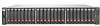
The following illustration shows controller module locations: 1. Controller A 2. Controller B Verifying module failure Before replacing the module, look at the event log, software management utilities, and device LEDs, to confirm that the module has failed. Table 1 LED descriptions Module LED Description OK LED • Solid Green = Module is operating normally • Blink = System is starting up • Off = Module is NOT operating normally Fault/Service Required LED • Solid Amber = Fault condition • Blinking Amber = Hardware-controlled power-up or cache flush/restore error • Off = No fault conditions Recording configuration settings As a best practice, record system settings before replacing a controller module. To obtain key settings using the SMU, in the Configuration View panel, select the system and then click the following menu options: • For date, time, and NTP settings: Configuration > System Settings > Date, Time • For system information (name, contact, location, and description): Configuration > System Settings > System Information • For user information: Configuration > Users > Modify User • For email notification settings: Configuration > Services > Email Notification • For SNMP notification settings: Configuration > Services > SNMP Notification • For information about scheduled tasks: View > Overview In the main section of the page, select Schedules. Scroll down to see details. • For information about all hosts (IDs and names): In the Configuration View panel, select Hosts and then click View > Overview. • For information about a specific host (IDs, names, and mappings): In the Configuration View panel, expand the display under Hosts and then select a specific host. • For overview information, including host IDs and nicknames, in the main section of the screen, select Host. Scroll down to see details. • For mapping information, in the main section of the screen, select Maps. Scroll down to see details. Enabling Partner Firmware Update nl (dual-controller configurations only) In a dual-controller configuration, the Partner Firmware Update option ensures that both controllers have the most recent version. HP recommends enabling this feature. To view or change the current Partner Firmware Update setting, select the system in the Configuration View panel and then select Configuration > Advanced Settings > Firmware. If needed, check the box and click Apply. Removing the failed module IMPORTANT: • In a single-controller configuration, if transporting the Com- pactFlash to a new controller, remove the controller only after the cache is copied to CompactFlash, which is indicated by the Cache Status LED being off. • In a single-controller environment, I/O must be stopped and the enclosure must be powered off prior to the replacement. • In a dual-controller environment, if the failed controller is first shut down, the controller may be hot-replaced in an operational enclosure. 1. In a dual-controller configuration, shut down the failed controller: a. Select the system in the Configuration View panel and then select Tools > Shut Down or Restart Controller. b. Set the following options and then click OK: • Operation=Shut down • Controller Type=Storage • Controller=A or B The blue OK to Remove LED on the controller illuminates to indicate that the controller can be safely removed. 2. Locate the enclosure in which the controller module OK to Remove LED is blue. 3. In a single-controller environment, stop all I/O and remove power from the enclosure. 4. Disconnect cables connected to the module. Label each cable to facilitate reconnection. Page 2
-
 1
1 -
 2
2 -
 3
3 -
 4
4
 |
 |